

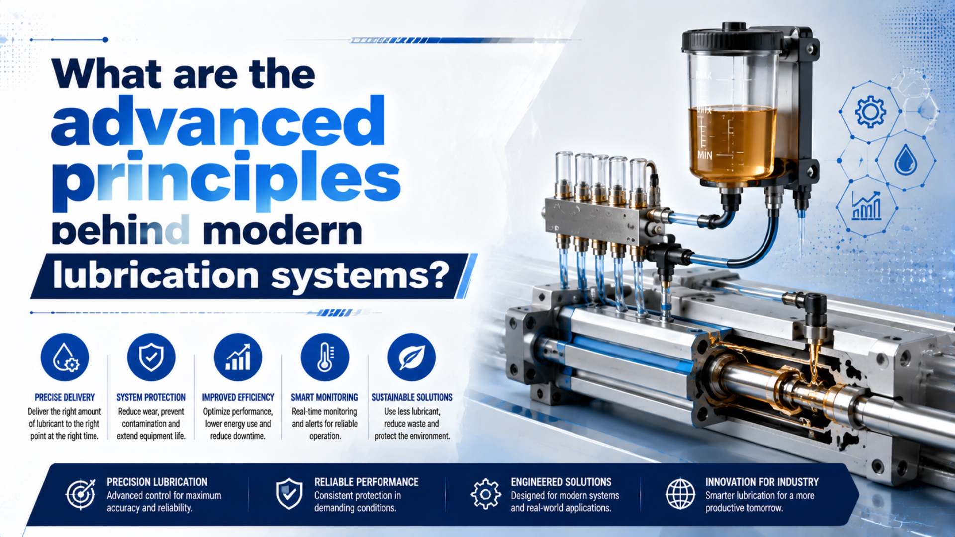
Modern lubrication systems do not simply add more oil. They control a complete state: the contact regime, lubricant chemistry, delivery quantity, temperature, contamination, seal compatibility, and evidence that the assembled machine still performs as required. In pneumatics, that state may rely on factory grease, deliberate oil mist, or a verified oil-free branch.
The most important boundary is application-specific. A lubricant that performs well in a four-ball EP test is not automatically suitable for a cylinder seal. An ISO viscosity grade does not identify its additives. A lubricator setting does not prove that oil reaches every downstream component in the right quantity.
Key Takeaways
- ISO 8573-1 classifies particles, water, and oil separately.
- Friction regime depends on the complete moving interface, not oil quantity alone.
- ISO VG32 identifies a viscosity grade, not complete chemistry or compatibility.
- Validate lubricant changes on the assembled pneumatic system.
A modern pneumatic lubrication system is the controlled combination of factory-applied grease, any deliberate airline oil, compressed-air purity, seal and surface materials, operating duty, inspection methods, and change records. Its purpose is stable motion and wear control without creating leakage, contamination, or an irreversible maintenance dependency.
The useful engineering question is not “Which lubricant is best?” It is “Which lubrication state was the component designed for, and what evidence shows that the installed system still remains inside that state?” That framing prevents oil grade, additive claims, and lubricator settings from being treated as independent shortcuts.
What Makes a Lubrication System Modern?
ISO 8573-1:2010 separates compressed-air purity into three principal contaminant groups: particles, water, and oil. It also identifies gaseous and microbiological contaminants. That structure shows why modern lubrication starts with system boundaries, because intentional oil, compressor carryover, water, and particles can reach the same sliding interface (ISO 8573-1, 2010).
A complete system has six linked functions:
| Function | Engineering question | Evidence to retain |
|---|---|---|
| Lubricant selection | Does the base oil, thickener, additive package, and viscosity suit the exact seal and surface? | Product data, safety data, compatibility approval |
| Storage and condition | Has heat, water, oxidation, separation, or contamination changed the lubricant? | Batch, storage date, container condition, sampling record |
| Delivery | Is lubricant factory-applied, manually applied, centrally metered, or carried as oil mist? | Assembly instruction, lubricator model, branch drawing, feed setting |
| Contact control | Is the interface operating in boundary, mixed, or local fluid-film lubrication? | Friction, speed, pressure, temperature, surface and seal data |
| Contamination control | What particles, water, cleaner, process media, or compressor oil can enter? | ISO air-quality class, filter and drain records, process exposure |
| Verification | Does the assembled component meet leakage, motion, temperature, and endurance limits? | Baseline test, acceptance limits, cycles or travel |
These functions cannot be approved separately. A compatible oil can still fail if it never reaches the contact. Reliable delivery can still cause trouble if the oil washes away factory grease, carries particles into a seal track, or contaminates a clean process.
The compressed-air quality standards guide explains how particles, water, and oil are specified and measured. That air-quality record should be part of the lubrication record, not a separate maintenance file.
Friction Regimes Inside Pneumatic Seals
A 2019 experimental study of commercial pneumatic cylinders reported that piston seals produced about 90% of measured friction in the tested configurations. Pressure affected friction more than velocity, and seal geometry also mattered. Lubrication analysis must therefore include pressure, seal design, diameter, direction, and speed rather than using speed alone (Tribology International, 2019).
Three regimes help describe a lubricated moving contact:
| Regime | How the load is carried | Pneumatic implication |
|---|---|---|
| Boundary lubrication | Surface asperities and adsorbed or reacted films carry much of the load | Breakaway friction, dwell, chemistry, and surface damage become important |
| Mixed lubrication | Fluid pressure and asperity contact share the load | Friction reflects both viscous shear and solid contact |
| Local fluid-film lubrication | Lubricant pressure separates part of the interface | Lower solid contact does not automatically mean zero leakage or zero wear |
A reciprocating seal may pass through more than one regime during a single stroke. Velocity falls to zero at reversal, pressure energizes the lip, and grease can redistribute during dwell. Surface texture, lip geometry, lubricant viscosity, temperature, stroke length, and contamination all change what happens next.
This is why a classic hydrodynamic wedge is not a complete pneumatic-cylinder model. A deformable seal is pressure energized, reverses direction, and has a limited lubricant inventory. The separate guide to hydrodynamic lubrication in cylinder seals covers film formation and the limits of the hydroplaning analogy.
Starvation deserves equal attention. A surface may have the right lubricant on paper but too little replenishment at the actual contact. Cleaning, long strokes, short repetitive strokes, high temperature, damaged wipers, or grease migration can expose a boundary-lubricated region. The boundary-lubrication failure guide shows how that condition differs from simple oil absence.
Why Is Viscosity Grade Not a Complete Lubricant Specification?
ISO 3448:1992 establishes one viscosity-classification system for industrial liquid lubricants, including mineral oils used for lubrication and related duties. An ISO VG number describes the viscosity class; it does not define the base oil, additive chemistry, seal compatibility, volatility, oxidation stability, or finished product approval (ISO 3448, 1992).
Viscosity still matters. If it is too high at startup, breakaway force and flow through a small metering path can increase. If it falls too far at operating temperature, film retention can weaken and leakage past clearances can change. Yet either diagnosis remains incomplete without the contact geometry, speed, pressure, surface texture, and actual lubricant supply.
Grease adds another layer. Its apparent consistency depends on the base oil, thickener, structure, temperature, shear history, and ageing. A cylinder assembled with grease is not simply using a “thicker oil.” The thickener helps retain and release base oil near the moving contact, while repeated motion, heat, water, contamination, or incompatible fluids can change that structure.
Treat viscosity as one field in the approval record:
- ISO viscosity grade or measured viscosity and test temperature
- Base-oil family and additive package
- Grease thickener and consistency when applicable
- Continuous and peak temperature
- Seal compound and factory lubricant
- Surface material, texture, pressure, speed, dwell, and stroke
- Cleaning agents, process media, water, and compressor carryover
Two products labeled ISO VG32 are not automatically interchangeable. The grease ageing guide explains why oxidation, separation, contamination, and mechanical working must be evaluated separately from the original viscosity label.
What Do Anti-Wear and EP Additives Actually Prove?
ASTM D2783-25 produces two principal results for lubricating fluids: a load-wear index and a weld point from a four-ball extreme-pressure tester. ASTM also states that users must determine whether the bench result correlates with field performance. An EP rating is therefore test evidence, not automatic approval for a pneumatic seal (ASTM D2783, 2025).
Anti-wear and extreme-pressure additives are intended to reduce damage when a fluid film alone cannot separate the surfaces. Depending on chemistry and operating conditions, they may adsorb, react, or form protective films on metallic contacts. Their usefulness depends on activation temperature, material pair, load, sliding mode, and the competing effects of the complete formulation.
That mechanism can matter in gears, bearings, compressors, and pneumatic tools. It should not be transferred blindly to cylinders:
- Many cylinder contacts include elastomers, polyurethane, PTFE-based materials, aluminum bores, plated rods, grease, and low-temperature reciprocation.
- An additive that protects a steel four-ball contact may swell a seal, disturb grease, leave deposits, or change low-speed friction.
- A high weld point does not measure air leakage, rod-seal wear, oil mist carryover, or compatibility with a downstream process.
- Additives do not repair misalignment, side load, a damaged counterface, abrasive contamination, or an incorrect seal profile.
Use bench tests to compare a defined property under a defined method. Then qualify the complete lubricant, seal, surface, and duty together. A product claim such as “EP fortified” is not a substitute for the cylinder manufacturer’s approved lubricant list.
Lubricant selection fails when a true property is used outside its evidence boundary. Viscosity, weld point, wear scar, dropping point, and compatibility rating can all be valid measurements. None of them, by itself, represents the operating pneumatic assembly.
Factory Grease, Airline Oil Mist, and Delivery Control
SMC states that applicable non-lube cylinders are lubricated for life at the factory. If additional lubrication is introduced, it specifies ISO VG32 turbine oil for the cited products and warns that the supply must continue because added oil can displace the original lubricant. Starting oil mist can therefore create a permanent maintenance dependency (SMC MGC Manual, accessed 2026).
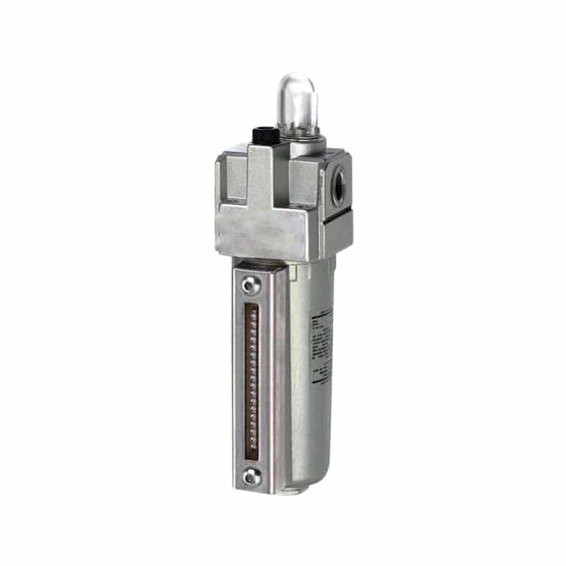
An air-line lubricator changes the lubrication state of every compatible downstream component on its branch.
Factory grease and airline oil solve different delivery problems:
| Delivery state | What it means | Main control risk |
|---|---|---|
| Factory-lubricated, no routine oil mist | Grease is applied during manufacture and retained by the qualified design | Cleaning, heat, contamination, or service work removes the original film |
| Deliberate continuous oil mist | A lubricator meters oil into an approved branch | Wrong oil, variable feed, empty bowl, branch-wide contamination, stopping later |
| Manual or maintenance relubrication | Grease or oil is applied during rebuilding or scheduled service | Wrong quantity, wrong location, mixed lubricants, assembly contamination |
| Incidental carryover | Compressor oil or residue reaches components unintentionally | Uncontrolled chemistry, unstable dose, exhaust contamination |
Festo describes one lubricator family as adding a finely adjustable quantity of oil and notes that the oil-mist proportion relates to compressed-air flow (Festo Air Lubricators, accessed 2026). A sight-feed adjustment is therefore not a universal drops-per-cycle specification. Flow range, mounting orientation, pressure, oil level, downstream distance, branch geometry, and the component manual still matter.
Before installing a lubricator, list every downstream valve, cylinder, quick exhaust, flow control, silencer, nozzle, sensor enclosure, and process interface. One device that prohibits oil, one exhaust that reaches product, or one branch that needs a different lubricant can invalidate the change.
The FRL maintenance guide covers bowl, drain, filter, regulator, and lubricator checks. The guide to pre-lube grease during cylinder break-in covers the separate assembly-lubrication problem.
How Do You Control Seal Compatibility and Contamination?
Parker lists six lubricant-selection requirements for O-ring applications, including dimensional compatibility, temperature stability, chemical stability, adhesion, contact-media compatibility, and avoiding blocked filters. The handbook also says lubricant choice is particularly important in dynamic pneumatic applications (Parker O-Ring Handbook, accessed 2026).
Material-family names are only a screening start. NBR, polyurethane, FKM, and PTFE-based seals each include many compounds and profiles. Fillers, cure systems, hardness, energizers, groove design, surface finish, and the actual oil additives can change swelling, shrinkage, friction, wear, and leakage.
ISO 1817:2024 evaluates vulcanized and thermoplastic rubber before and after immersion in test liquids. It can support compatibility screening for a named liquid, temperature, time, specimen, property, and acceptance limit. It does not qualify a moving seal, groove, counterface, lubricant mixture, or complete cylinder by itself (ISO 1817, 2024).
Use an evidence ladder:
- Confirm the exact lubricant, factory grease, cleaner, process media, and compressor carryover.
- Identify every seal by position, profile, compound code, and revision.
- Review manufacturer compatibility data for the exact materials and temperature.
- When data are incomplete, agree on an immersion test with declared measurements and limits.
- Test the assembled cylinder for leakage, friction, motion, temperature, and surface condition.
- Monitor the production branch against the same baseline.
For food, pharmaceutical, cosmetic, or related processes, hygiene adds another boundary. ISO 21469:2006 addresses the formulation, manufacture, use, and handling of lubricants that may contact products incidentally. It does not cover substances intended for direct product contact and does not replace machine-specific contamination control (ISO 21469, 2006).
The air lubrication and seal-material guide provides the detailed compound-selection workflow. Valve branches require their own review because unlubricated air can affect spool-valve seals differently from a piston or rod seal.
How Should You Approve and Monitor a Lubrication Change?
ISO 19973-3:2015 expresses pneumatic-cylinder reliability in two service measures, cycles or kilometres, and specifies test procedures and threshold levels for piston-rod cylinders. A lubrication change should therefore be assessed against declared duty and failure limits, not a calendar-life promise or one smooth commissioning stroke (ISO 19973-3, 2015).
Use a controlled change process:
| Stage | Required record | Reject or investigate when |
|---|---|---|
| Define | Component models, seal kits, surfaces, duty, current grease or oil, air quality | Installed identity or current lubrication state is unknown |
| Screen | Proposed lubricant, additives, viscosity, temperature, materials, process restrictions | Compatibility or process evidence is incomplete |
| Bench check | Agreed material test, lubricant condition, metering or application method | Test method does not represent the decision being made |
| Assemble | Quantity, location, cleanliness, seal orientation, torque, surface condition | Assembly differs from the released procedure |
| Function test | Leakage, breakaway, running motion, stroke time, temperature, cushioning | Results exceed declared limits or differ materially from baseline |
| Endurance and release | Cycles or travel, inspection interval, failure thresholds, approval owner | Trend worsens or the original failure mode returns |
ISO 10099:2001 provides final functional examination and acceptance criteria for double-acting, single-rod pneumatic cylinders (ISO 10099, 2001). Use it where applicable, then add the machine-specific load, speed, temperature, contamination, dwell, and lubrication conditions that the standard cannot infer.
Monitor outcomes rather than oil appearance alone. Useful signals include breakaway pressure, loaded stroke time, dynamic port pressure, leakage location, surface temperature, noise, exhaust oil, rod or bore condition, seal dimensions, filter differential condition, drain history, and lubricant consumption. Record operating state and measurement method with every result.
The strongest monitoring signal is a change from a controlled baseline, not an isolated absolute value. A rise in breakaway pressure means little without the same load, temperature, dwell, direction, air quality, and measurement method. Good lubrication data preserve the operating context that makes comparison possible.
Advanced Lubrication System FAQs
ISO 10099 covers final functional testing for one defined cylinder class, while ISO 19973-3 reports reliability in cycles or kilometres. Together they illustrate a central rule: lubrication evidence must be attached to the exact component, test condition, and acceptance limit. These answers preserve that boundary for common maintenance decisions.
Is ISO VG32 always the correct oil for pneumatic equipment?
No. ISO VG32 identifies a viscosity grade under ISO 3448, not a complete lubricant approval. SMC specifies ISO VG32 turbine oil for cited products, but another component may require different chemistry or prohibit added oil. Follow every downstream model manual and verify seals, temperature, process contamination, and factory grease.
Should a non-lube cylinder receive airline oil?
Only when its model-specific instructions permit it and every downstream component accepts the change. SMC warns that introduced oil can displace factory lubricant and must then be supplied continuously. Confirm the oil grade, branch layout, exhaust destination, refill ownership, and commissioning limits before installing a lubricator.
Does an EP additive prevent pneumatic-cylinder seal wear?
Not by itself. ASTM D2783 measures load-wear index and weld point in a steel four-ball test. It does not test a pneumatic seal, coated bore, plated rod, leakage path, or oil mist branch. Use EP results for their declared bench purpose, then qualify the complete lubricant and cylinder.
How can you tell whether a cylinder has a lubrication problem?
Define the symptom and compare it with a controlled baseline. Record breakaway pressure, loaded stroke time, port pressure, temperature, leakage location, surface condition, air quality, lubricant history, and dwell. First exclude side load, misalignment, contamination, damaged surfaces, valve leakage, and incorrect flow control.
What evidence is needed before changing cylinder grease or oil?
Record the exact cylinder, seal kit, surfaces, current grease, proposed lubricant, air quality, duty, cleaners, and process restrictions. Add material compatibility evidence, the released application method, functional acceptance limits, endurance or follow-up criteria, and an approval owner. A generic compatibility chart or smooth trial stroke is insufficient.
Sources and technical references
- ISO 8573-1:2010, Compressed air - Part 1: Contaminants and purity classes, retrieved 2026-07-27.
- Experimental study of friction in pneumatic seals, Tribology International, retrieved 2026-07-27.
- ISO 3448:1992, Industrial liquid lubricants - ISO viscosity classification, retrieved 2026-07-27.
- ASTM D2783-25, Extreme-pressure properties of lubricating fluids, retrieved 2026-07-27.
- SMC MGC Series operation manual, retrieved 2026-07-27.
- Festo air lubricators, retrieved 2026-07-27.
- Parker O-Ring Handbook, retrieved 2026-07-27.
- ISO 1817:2024, Rubber - Determination of the effect of liquids, retrieved 2026-07-27.
- ISO 21469:2006, Lubricants with incidental product contact, retrieved 2026-07-27.
- ISO 19973-3:2015, Reliability testing for pneumatic cylinders with piston rods, retrieved 2026-07-27.
- ISO 10099:2001, Pneumatic cylinders - Final examination and acceptance criteria, retrieved 2026-07-27.