

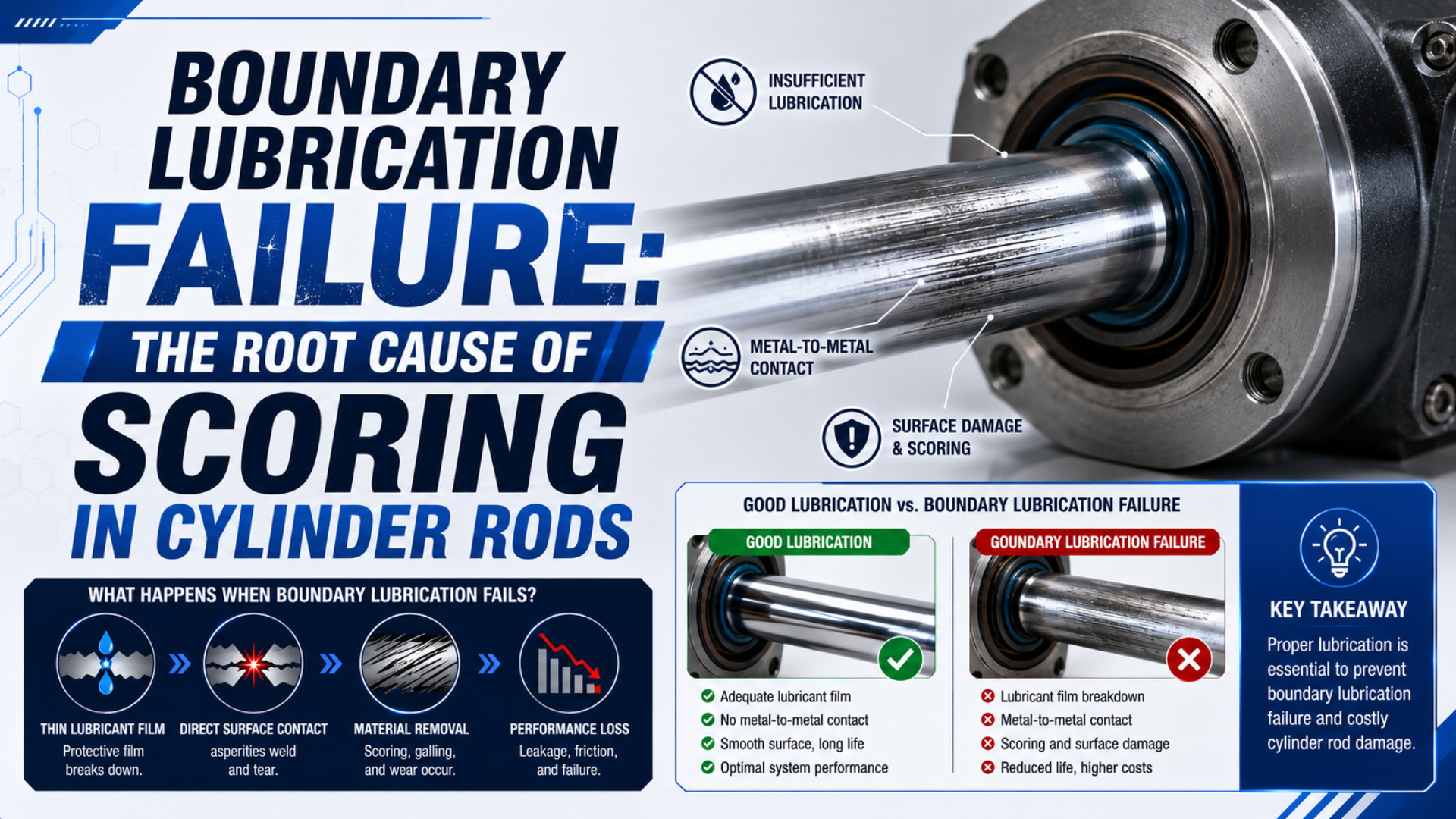
Cylinder rod scoring is permanent surface grooving along the moving rod. Boundary lubrication can participate in that damage, but it is not a complete root-cause diagnosis. It describes a sliding condition in which the lubricant film does not fully separate opposing surface features. The initiating fault may instead be misalignment, side load, a damaged wiper, embedded contamination, corrosion, incompatible lubricant, a bent rod, or a surface defect.
The useful maintenance question is therefore not simply, “Did the lubricant fail?” It is, “What forced this rod, bearing, seal, and lubricant system outside the operating conditions approved for the exact cylinder?” Damage direction, location, residue, surface measurements, and machine geometry can answer that question before another seal kit is installed.
Key Takeaways
- Boundary lubrication is a contact regime, not proof of one universal root cause.
- One-sided, distributed, pitted, and glazed rod damage point to different inspections.
- Preserve installed orientation and residue before cleaning or rotating parts.
- Use only model-approved lubricant, surface limits, repair methods, and seal kits.
What Does Boundary Lubrication Mean at a Cylinder Rod Interface?
Boundary lubrication is 1 of 3 broad sliding regimes commonly separated in tribology: full-film, mixed, and boundary. The transition depends on load, speed, viscosity, surface texture, and geometry, not speed alone (ASME Journal of Tribology). In boundary operation, surface features can share load while a thin adsorbed or chemically active lubricant layer still influences friction and wear.
A pneumatic cylinder rod passes through several components with different functions. The external wiper limits contaminant entry. The pressure seal retains compressed air. A bearing or guide bushing supports the rod. Depending on the model, these components may be elastomer, engineered polymer, composite, bronze, or another material. The interface is not automatically bare steel sliding directly on bare steel.
During reversal, start-up, slow movement, high local contact pressure, or lubricant depletion, the sliding interface may spend more time in mixed or boundary conditions. That state can raise friction and make existing alignment or contamination problems more damaging. It does not establish which condition initiated the contact.
For a separate review of retained factory grease and air-line oil, see the effects of dry, non-lubricated air on cylinders.
Why Is Boundary Lubrication a Mechanism Rather Than the Complete Root Cause?
Parker’s pneumatic maintenance guidance identifies at least 3 separate contributors relevant to rod damage: a rough or scored rod, improper piston-rod alignment, and external hazards such as weld spatter or paint (Parker Automation Products). That fault structure is broader than “insufficient grease,” even when boundary contact appears in the final wear sequence.
Consider a cylinder mounted slightly out of line with an external guide. The connection pushes the rod against one sector of its bearing. Local contact pressure rises, the lubricant distribution changes, and any trapped particle becomes more aggressive. Boundary lubrication may explain the final friction and wear mechanism, but alignment created the condition.
The same distinction applies to contamination. A damaged wiper can carry an abrasive particle onto an otherwise correctly lubricated rod. The particle cuts a longitudinal track, damages the pressure-seal lip, and releases more debris. Adding grease without removing the particle source can spread the abrasive and conceal the evidence.
The strongest diagnosis links 4 levels of evidence: the machine condition, the loaded component, the observed contact state, and the visible damage. Stopping at the contact state is like calling an overheated bearing “a heat failure” without asking why the load, clearance, lubricant, or contamination changed.
| Diagnostic level | Question to answer | Example evidence |
|---|---|---|
| Machine condition | What changed the intended load or environment? | Binding guide, new tooling, damaged shield, washdown chemical |
| Component response | Which part carried abnormal load or admitted debris? | One-sided bushing polish, cut wiper, bent rod |
| Contact state | How did the sliding interface behave? | Stick-slip, lubricant displacement, boundary contact |
| Damage result | What permanent mark remains? | Axial groove, pitting, coating loss, torn seal lip |
If the bearing and seal are worn on one clock position, use the dedicated guide to cylinder side-loading and rod-bearing wear before treating lubrication as the sole correction.
What Does the Cylinder Rod Scoring Pattern Reveal?
Parker tells technicians to examine the rod for 3 named surface defects, dents, gouges, and score marks, and to replace a rod that is rough (Parker Automation Products). Those categories make the surface an evidence record. Direction, depth, distribution, and clock position matter more than the generic label “scored.”
Mark the installed top of the rod, gland, and cylinder before disassembly. Photograph the rod extended, then record where each mark begins and ends. Do not rotate the rod or clean the gland until residue, embedded particles, and seal-lip damage are documented. A mark that repeats on one side carries different information from scratches distributed around the circumference.
| Rod evidence | More likely inspection path | What must still be ruled out |
|---|---|---|
| One-sided longitudinal scoring | Side load, guide conflict, mount movement, bent rod, bearing clearance | Particle trapped at one bearing sector |
| Multiple parallel scratches around the rod | External contamination, failed wiper, dirty assembly, piping debris | Rough mating surface or damaged lead-in edge |
| Pits, rust staining, or coating blisters | Condensation, chemical exposure, coating porosity, external washdown | Impact marks or residue deposited after failure |
| Glazing, discoloration, chatter, or stick-slip | Friction change, lubricant depletion, wrong lubricant, seal incompatibility | Low dynamic pressure, flow restriction, or misalignment |
| Isolated dent or circumferential nick | Tool impact, clamp damage, installation accident, collision | Manufacturing or plating defect |
Inspect the rod seal and guide together. A scored rod can abrade a new seal, while an enlarged or damaged bearing can force a good rod through the seal eccentrically. The piston rod seal leak guide shows why visible leakage is evidence rather than a complete diagnosis. The comparison between sealing functions is covered in dynamic versus static cylinder seals.
How Do Side Load, Contamination, and Corrosion Create Similar Damage?
Parker recommends checking rod alignment in 2 positions, extended and retracted, because improper alignment can cause excessive rod-gland and cylinder-bore wear (Parker Automation Products). That two-position check is a minimum screen. A production load can still deflect the frame or guide differently at mid-stroke.
Side load and misalignment
Side load biases the rod against one bearing sector. Common sources include a rigid connection to a nonparallel rail, unsupported tooling, loose mounts, constrained pivots, frame deflection, and thermal movement. Compare unloaded and loaded alignment at retracted, mid-stroke, and extended positions. Record rod runout, guide play, bracket movement, and the clock position of bearing polish.
A larger cylinder does not automatically correct this condition. More bore raises axial force, but it can also increase the force available to drive a binding mechanism. Correct the guidance and connection geometry instead of using pressure to overcome friction.
External and internal contamination
External dust, weld spatter, dried coolant, abrasive powder, or cleaning residue can enter across a damaged or unsuitable wiper. Internal contamination can arrive through tubing, thread debris, corrosion scale, seal fragments, or poor assembly practice. Preserve particles with their location. Laboratory identification is more useful than describing every dark residue as “metal” or “compressor oil.”
If several actuators on one branch develop similar scratches, inspect filtration, drains, piping work, and upstream failures. If only one rod shows one-sided damage, prioritize the local guide, mount, and exposure. The wider barrel-scoring and piston-damage guide covers evidence that extends inside the cylinder.
Corrosion and chemical exposure
Pits and blistered coating can cut a seal even when the cylinder was originally aligned and lubricated correctly. Check condensation, outdoor storage, washdown chemicals, process mist, and the compatibility of rod coating, wiper, seal, and lubricant. A material photograph or “stainless” label does not establish resistance to the actual chemical concentration, temperature, dwell, and cleaning procedure.
Why Must Lubricant and Surface Specifications Be Model-Specific?
One SMC cylinder instruction specifies turbine oil Class 1, ISO VG32, with no additives when lubrication is used, and says lubrication must continue once started (SMC product manual). That explicit rule conflicts with generic advice to add any PTFE, molybdenum-disulfide, or extreme-pressure grease to a rod seal.
Lubricant choice depends on the seal compound, guide material, factory grease, temperature, air treatment, process cleanliness, and manufacturer qualification. An additive that benefits one metal contact may swell an elastomer, disturb retained grease, contaminate a process, or increase breakaway friction elsewhere. The correct product name, quantity, application point, and relubrication policy must come from the exact cylinder documentation.
Parker’s 0900P pneumatic catalog illustrates this specificity. It identifies a seal-compatible cylinder lubricant for normal operation and separately calls for molybdenum-disulfide grease on tie-rod threads and bearing faces during assembly (Parker Pneumatic Catalog 0900P). A lubricant approved for a fastener is not automatically approved at a dynamic seal lip.
Surface specifications need the same discipline. Arithmetic average roughness, Ra, cannot describe isolated scratches, profile shape, peak density, directionality, coating adhesion, hardness, straightness, or waviness by itself. Trelleborg’s hydraulic sealing guide explicitly says Ra and Rz alone are insufficient and adds material ratio, Rmr, to its assessment (Trelleborg Hydraulic Seals). Its numerical limits apply to the stated hydraulic seal systems, not automatically to pneumatic rods.
A rod can pass one average-roughness reading and still destroy a seal because a single axial groove creates a leakage path. Conversely, a visible mark may be acceptable only if the cylinder manufacturer permits it after depth, coating, straightness, and functional inspection. Do not invent a universal “ideal” Ra or hardness from another product family.
What Teardown and Measurement Workflow Finds the Initiating Cause?
OSHA’s energy-control rule treats pneumatic energy as an energy source and requires covered procedures to control hazardous stored energy before servicing (OSHA 29 CFR 1910.147). A scoring investigation therefore starts with the machine’s approved isolation procedure, secured loads, relieved pressure, and verification of the safe state, not with loosening a port.
Use this evidence-preserving sequence:
- Record the operating event. Note whether leakage, chatter, binding, or noise occurred on extension, retraction, reversal, dwell, or impact. Capture supply and dynamic pressure, speed, load, temperature, and recent machine changes.
- Preserve orientation. Mark cylinder top, rod clock position, gland, ports, mounts, and load direction. Photograph the exposed rod and contamination before wiping.
- Inspect the machine first. Check guide parallelism, coupling freedom, mount movement, pivot action, hard stops, and frame deflection across the full stroke and under representative load.
- Inspect the rod end as a system. Keep the wiper, pressure seal, bearing, and deposits in order. Compare their clock-position wear and identify where scratches begin relative to the gland.
- Measure the rod. Follow the manufacturer procedure for diameter, straightness or runout, surface condition, coating damage, and permissible defects. Do not polish before measurements are complete.
- Identify materials and lubricant. Record the complete cylinder code, seal kit, rod treatment, lubricant product, added airline oil, cleaning chemicals, and any unapproved substitution.
- Trace contamination. Compare rod debris with material in the wiper, ports, tubing, filter bowl, valve, and nearby process. Retain labeled samples when identification could change the corrective action.
- Test the hypothesis. The proposed cause should explain the installed direction, damaged parts, timing, and operating change. If it explains only one observation, keep competing branches open.
In our experience, the most valuable evidence is often lost during the first 10 minutes of a teardown. Cleaning the rod, rotating the gland parts, and discarding the wiper can erase the relationship among load direction, embedded debris, and seal-lip damage. Photograph and label first; clean only after the inspection plan is recorded.
Do not run production cycles merely to reproduce a damaging symptom. If controlled motion is needed, use the machine’s approved diagnostic procedure and keep personnel outside the hazard zone.
Which Controls Prevent Repeat Scoring and Support Return to Service?
ISO 4414 covers pneumatic-system design, construction, modification, installation, and use rather than treating the actuator as an isolated part (ISO 4414:2010). Repeat-scoring prevention should therefore address at least 4 boundaries: machine load path, external exposure, compressed-air path, and model-specific cylinder assembly.
Correct the initiating condition
- Align the cylinder and external guide through the full stroke under representative load.
- Use a suitable guided axis, floating connection, pivot arrangement, shield, bellows, or scraper when the application requires it.
- Repair loose mounts, bent brackets, binding rails, shifted stops, and process-contact changes.
- Define particle, water, and oil requirements at the point of use, then verify filters, drains, dryers, piping, and maintenance cleanliness.
Restore only to approved limits
Parker’s guidance to replace a rough rod is a practical default, but the final decision remains model-specific. A qualified manufacturer or rebuilder may permit repair, recoating, or replacement after measuring groove depth, straightness, diameter, coating condition, and surface texture. A seal-only repair is not defensible when the mating rod or supporting bearing remains outside limits.
Use the exact wearing-parts kit, seal material, approved lubricant, assembly tools, torque values, and cleaning method. If a field-repair method is unavailable, the pressure boundary is damaged, or measurements cannot be verified, replace the assembly or send it to an authorized repair facility. The repair-versus-replace framework can be applied after the technically acceptable options are known.
Validate the corrected system
Before production release, leak-test both directions and cycle slowly under the approved procedure. Confirm smooth motion, full stroke, sensor operation, cushion behavior, dynamic pressure, and absence of scraping. Reintroduce the load in a controlled way, then verify alignment, speed, repeatability, and product quality.
Record the original evidence, confirmed cause, corrective action, replaced parts, measurements, test conditions, and acceptance criteria. Schedule an early follow-up inspection. A durable repair changes the condition that created the mark, not merely the component that displayed it.
Cylinder Rod Scoring FAQs: What Should Maintenance Teams Ask?
Parker separates 3 rod-leak branches in its pneumatic guidance: worn or damaged seals, excessive gland clearance, and seal-material deterioration (Parker Automation Products). These 5 answers keep rod scoring, lubrication state, speed, seal replacement, and repair decisions inside that wider fault tree.
Is boundary lubrication always a cylinder fault?
No. Boundary lubrication is a normal tribological regime that can occur during start-up, reversal, or other demanding sliding conditions. It becomes damaging when the model’s surface, lubricant, load, alignment, contamination, speed, or temperature limits are exceeded. Diagnose the initiating condition instead of treating the regime itself as a defective part.
Does slow cylinder speed automatically cause rod scoring?
No. Low speed can increase time in mixed or boundary conditions and reveal stick-slip, but it does not prove a scoring cause. Alignment, side load, surface texture, lubricant compatibility, pressure, seal design, and contamination still matter. Compare the actual duty with the exact cylinder’s approved speed and load range.
Can adding grease stop a scored rod from leaking?
Grease may temporarily change friction or leakage, but it cannot restore removed coating, straighten a bent rod, remove an embedded particle, or correct misalignment. An unapproved grease can also conflict with the seal or factory lubricant. Preserve evidence first, then use only the model-specific lubricant and repair procedure.
Can I install a new rod seal on a visibly scored rod?
Only if the rod passes the cylinder manufacturer’s inspection and repair limits. A groove can abrade the new lip or form a leakage path, while a damaged bearing can repeat the eccentric load. Measure rod condition, straightness, coating, gland clearance, and bearing wear before deciding that a seal kit is sufficient.
Does one-sided scoring prove cylinder side load?
It strongly prioritizes alignment, runout, guide, mount, and load-direction checks, but it is not proof by itself. A particle trapped at one bearing sector can create a similar line. Confirm that rod, bearing, seal, machine geometry, and installed clock position all support the same cause before closing the investigation.
Sources and technical references
- Parker Automation Products, pneumatic cylinder maintenance, rod condition, alignment, seal leakage, and environmental protection; retrieved 2026-07-22.
- Parker Pneumatic Catalog 0900P, model-specific cylinder lubricant and assembly-lubricant locations; retrieved 2026-07-22.
- SMC Product Manual, Doc. 1082441, approved airline lubricant and continuity warning for the stated products; retrieved 2026-07-22.
- ASME Journal of Tribology, “Simulations and Measurements of Sliding Friction Between Rough Surfaces in Point Contacts”, mixed, full-film, and boundary lubrication behavior; published 2007.
- Trelleborg Hydraulic Seals, surface-parameter limitations and hydraulic-specific examples; retrieved 2026-07-22.
- OSHA 29 CFR 1910.147, control of hazardous energy during service and maintenance; retrieved 2026-07-22.
- ISO 4414:2010, general rules and safety requirements for pneumatic systems; confirmed 2021.