

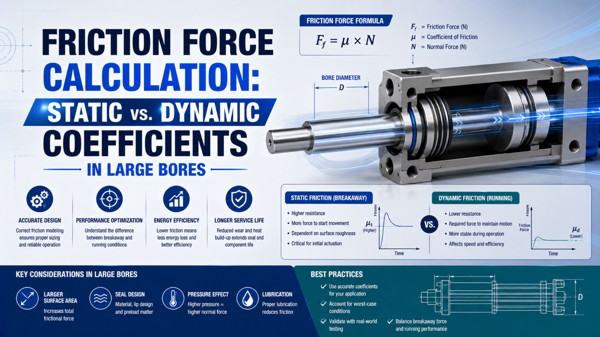
For a large-bore pneumatic cylinder, don’t calculate seal friction by assigning one static coefficient and one dynamic coefficient to the payload. Measure the pressure at both cylinder ports, calculate the net pressure force, and compare it with the external load at breakaway and during a stable running window.
This approach separates three different questions: how much pressure force is available, how much resistance exists before motion, and how much resistance remains once the piston is moving. The distinction matters when a cylinder starts abruptly, stalls after a long dwell, or runs smoothly at one speed but not another.
Key Takeaways
- SMC says cylinder sliding resistance changes with pressure, model, and bore.
- Breakaway friction and running friction require separate, defined test windows.
- Large bore does not create a universal friction percentage.
- Use synchronized port pressures, effective areas, external load, and acceleration to infer installed friction.
Why Doesn’t the Basic Coefficient Formula Describe Cylinder Seal Friction?
Parker notes that break-out friction can reach three times running friction for one specified 70-durometer O-ring and surface condition, while also warning that seal friction is difficult to predict (Parker O-Ring Handbook, accessed 2026-07-22). That conditional example is not a universal pneumatic-cylinder ratio.
The familiar dry-friction relationship is:
Here, is friction force, is the coefficient for a defined pair of surfaces and motion state, and is the normal contact force. The equation is useful when both and are known under representative conditions. A pneumatic cylinder seal pack rarely meets that requirement.
The payload isn’t the normal force acting on the piston and rod seals. Seal contact is created by installed squeeze, lip geometry, material deformation, pressure energization, surface finish, lubrication, temperature, wear, and side loading. The piston seal, rod seal, wear bands, guide, and external mechanism can also contribute different amounts of resistance. The companion static and dynamic cylinder seal guide explains the different sealing duties.
A value labeled “static coefficient” therefore can’t be multiplied by a 500 kg payload to obtain cylinder seal friction. That calculation mixes an external load with an internal contact force. It may also omit back pressure on the exhaust side, which can be larger than the friction term in a restricted meter-out circuit.
The coefficient model still has a limited use. If an external slide has a measured coefficient and a known normal load, calculate that slide resistance separately. Keep it in the external-load term rather than treating it as a cylinder-seal coefficient.
How Should Static and Dynamic Friction Be Defined in a Pneumatic Cylinder?
SMC lists 0.5 MPa sliding-resistance guides of 19 to 102 N for representative standard cylinders from 40 to 100 mm bore, and states that resistance varies with pressure, model, and bore (SMC Basic Characteristics of Air Cylinders, accessed 2026-07-22). A test result needs the same context.
For cylinder diagnostics, use operational definitions rather than assumed coefficients:
- Breakaway friction is the resisting-force estimate at the threshold of first detectable motion after a defined dwell.
- Peak starting resistance is the highest inferred resistance during the transition from rest to motion. It can include acceleration and pressure-sensor timing effects, so it isn’t automatically identical to breakaway friction.
- Running friction is the average or median inferred resistance over a stated constant-direction, nearly constant-speed window away from cushioning and end stops.
- Stick-slip is repeated alternation between sticking and moving. One breakaway peak by itself does not prove stick-slip.
Why define both a threshold and a peak? A displacement sensor may identify first motion after the chamber pressure has already reached its maximum, while a slow pressure channel may report that maximum later. The sampling rate, sensor response, filtering, and timestamp alignment can change the apparent peak.
Record the dwell time before every start. Parker identifies stationary contact time as one factor that affects break-out friction, alongside rubber hardness, surface condition, squeeze, lubrication, pressure, and temperature. A warm restart after one second and a cold restart after a weekend are different tests.
The running window also needs boundaries. Exclude initial acceleration, valve switching, cushion entry, stop contact, and direction reversal. If speed varies materially inside the chosen window, report friction against speed instead of compressing the stroke into one number.
Does a Larger Bore Automatically Increase the Friction Problem?
ISO 15552 covers detachable-mounting pneumatic cylinders from 32 to 320 mm bore, a tenfold diameter range (ISO 15552:2018, confirmed 2026-07-22). Across that range, pressure force and seal geometry do not scale in the same way, so bore alone cannot determine a friction percentage.
Full piston area is:
The piston circumference is:
is piston area, is circumference, and is bore diameter. Doubling makes the area four times larger and the circumference twice as large. This geometric comparison explains why a larger cylinder can have more absolute friction yet a smaller friction-to-theoretical-force ratio.
It does not prove that seal friction is proportional to circumference. Seal profile, pressure-energized contact width, material, barrel finish, wear-ring design, rod diameter, and guide load still control the actual resistance. Compare only like-for-like product families under the same pressure, speed, temperature, direction, dwell, and lubrication condition.
Large bore changes another quantity that a percentage hides: stored pneumatic energy. A large chamber can release more energy when stiction breaks, even when friction represents a modest share of theoretical force. Abrupt motion may therefore reflect the combined effects of compressible-air storage, valve flow, structure, load, and friction, not an unusually high coefficient alone.
For sizing, calculate ideal push or pull force first with the Cylinder Force Calculator. Then replace its generic friction allowance with model-specific data or an installed measurement when low-speed smoothness, long dwell, or a small force margin matters.
How Can Friction Be Calculated From Two Port Pressures?
NIST defines the pascal as one newton per square metre, so 1 MPa equals 1 N/mm² (NIST Guide to the SI, accessed 2026-07-22). This equivalence makes a two-pressure cylinder force balance convenient in millimetres and newtons.
For a single-rod, double-acting cylinder, calculate the rod-side annular area:
is annular area, is bore diameter, and is rod diameter. During extension, the net pneumatic force before mechanical resistance is:
is cap-end gauge pressure and is rod-end gauge pressure at the same instant. Both transducers should be installed close to the cylinder ports. An upstream regulator gauge cannot reveal the pressure lost through the valve and tubing or the pressure retained on the exhausting side.
The installed resisting-force estimate during extension is:
is the signed external resistance, including the relevant gravity and process-load components, is the moving mass, and is acceleration along the cylinder axis. Define positive direction and signs before calculating. For retraction, swap the driving and opposing pressure-area terms.
At the instant just before detectable motion, acceleration is approximately zero. The breakaway estimate becomes the net pressure force minus the known external resistance. Once motion begins, keep the $m a(t)$ term unless the selected running window has verified near-zero acceleration.
What if there is no load cell? Use a calibrated known load or an unloaded fixture with a controlled orientation, then state that the residual includes cylinder seals, bearings, guides, hose drag, alignment error, and any unmeasured external resistance. Call it installed resistance, not pure seal friction.
Do not subtract a separate leakage percentage after using measured chamber pressures. If leakage changes either chamber pressure, that effect is already present in the pressure-force terms. Leakage still deserves a separate diagnostic test, but deducting it again would double-count its force effect.
A Repeatable Large-Bore Friction Test
ISO 19973-3:2015 supplies test and reporting procedures for both single-acting and double-acting pneumatic cylinders with piston rods (ISO 19973-3, confirmed 2026-07-22). A field friction test is narrower than that reliability standard, but it needs the same discipline: defined equipment, conditions, threshold, repetitions, and reporting.
Use this sequence:
- Define the motion state. Record extension or retraction, start position, target speed, payload, orientation, dwell time, ambient temperature, air temperature, and lubrication condition.
- Check the mechanics. Isolate side load, tight clevises, guide preload, hose drag, contamination, and stop contact before assigning the residual to seals.
- Install synchronized sensors. Measure both port pressures, displacement or velocity, and external force when practical. Use a sampling rate and sensor bandwidth that can capture the starting event.
- Establish a first-motion threshold. State the displacement or velocity threshold used to declare breakaway. Keep it above sensor noise and unchanged across comparisons.
- Run a dwell matrix. Include the actual production dwell and any cold-start condition that matters. Randomize or document the order if temperature rises across repeated cycles.
- Capture complete strokes. Record enough pre-trigger data to see pressure build before motion, then retain acceleration, stable travel, deceleration, cushioning, and the end stop.
- Choose the running window. Use a central region with constant direction and nearly constant speed. Report its position and duration.
- Repeat both directions. A single-rod cylinder has different effective areas, and exhaust restrictions may not be symmetric.
- Report dispersion. Give the individual results plus median, minimum, and maximum. A single “best” cycle conceals unstable behavior.
Use the same valve state and flow-control settings across tests. A meter-out restriction can raise exhaust-side pressure and change the apparent starting event. The related cylinder force-loss guide explains how supply loss and back pressure fit into the complete force balance.
Reading the Force Trace Without Mislabeling Every Peak
One Festo cylinder datasheet lists 4,712 N theoretical advance force at 6 bar and 160 N friction for that specific configuration, a ratio of about 3.4% (Festo datasheet 1691433, accessed 2026-07-22). That is product data, not a universal allowance.
Align pressure, position, velocity, acceleration, and load on one time base. Then divide the trace into physical events:
| Trace region | What to calculate | Common interpretation error |
|---|---|---|
| Pressure build while stationary | Net pressure force at first motion | Calling the regulator setting “breakaway pressure” |
| First displacement samples | Starting transition and acceleration | Treating every peak as static seal friction |
| Constant-speed middle stroke | Median or mean installed resistance | Including cushion or valve-switching transients |
| Repeated speed oscillation | Resistance versus velocity and chamber pressure | Blaming seals without checking valve flow and structure |
| Cushion and end stop | Deceleration and impact behavior | Mixing end-of-stroke force with running friction |
Plot inferred resistance against velocity as well as time. A recurring loop between resistance and velocity can reveal direction dependence, pressure timing, or stick-slip more clearly than a single peak-to-average ratio. If the loop changes when only the valve restriction changes, the pneumatic circuit is part of the behavior.
A higher start value after a longer dwell points toward time-dependent seal and lubricant behavior, but it is not proof by itself. Confirm that temperature, load, port pressures, direction, and mechanical alignment remained comparable. If both chamber pressures look normal but installed resistance rises, inspect seals, wear bands, guides, contamination, and mounting.
If the active-port pressure collapses during motion, investigate supply flow and valve capacity. If the opposing-port pressure remains high, investigate exhaust restriction. If the calculated resistance becomes negative, check sign conventions, pressure zeroing, force-sensor direction, effective areas, and timestamp alignment before drawing a mechanical conclusion.
Using the Measurement in Cylinder Selection
The same Festo example pairs 160 N stated friction with 4,712 N theoretical advance force at 6 bar, but SMC warns that sliding resistance changes with pressure and product configuration (Festo; SMC, accessed 2026-07-22). Use the selected model’s data before applying a measured analogue.
Separate the physical force balance from the design margin:
- Calculate pressure force using the minimum expected pressures at both cylinder ports.
- Subtract measured or model-specific breakaway resistance for the starting check.
- Subtract measured running resistance for the continuous-motion check.
- Add gravity, process load, acceleration, hose or cable drag, and guide resistance as explicit terms.
- Apply a justified margin for measurement uncertainty and operating variation after the losses are identified.
A safety factor isn’t a friction measurement. Keeping those two quantities separate lets an engineer update the calculation when dwell, temperature, speed, valve restriction, or payload changes. It also prevents the same uncertainty from being counted once as a “friction percentage” and again as a final selection factor.
For a replacement cylinder, request the manufacturer’s minimum operating pressure or sliding-resistance data at the relevant bore and pressure. Also compare rod diameter, seal option, guide arrangement, allowed side load, operating-speed range, cushioning, and mounting. Matching ISO envelope dimensions does not guarantee matching starting behavior.
When motion quality is the problem, increasing bore or supply pressure may only store more energy before release. First determine whether the limiting mechanism is breakaway resistance, exhaust back pressure, insufficient valve flow, side loading, weak guidance, or structural compliance. The minimum operating pressure guide and breakaway force guide cover those adjacent checks.
Large-Bore Cylinder Friction FAQs
SMC’s published 0.5 MPa guide spans 19 to 102 N for representative 40 to 100 mm standard cylinders, demonstrating why one friction coefficient cannot represent every bore and model (SMC, accessed 2026-07-22). These answers keep the test conditions attached to the result.
What static friction coefficient should I use for a pneumatic cylinder?
Don’t assign one universal coefficient to the complete cylinder. Use the selected model’s minimum operating pressure or sliding-resistance data, or measure installed resistance from synchronized port pressures and external load. A coefficient is appropriate only for a defined contact pair whose normal force and test conditions are known.
Is breakaway friction always higher than running friction?
Not by a fixed percentage. Breakaway resistance can rise with dwell and seal contact conditions, but the observed start peak may also include acceleration, sensor timing, back pressure, guide resistance, and structural release. Compare a defined first-motion threshold with a separate constant-speed window under the same load, direction, temperature, and pressure conditions.
Why can a large-bore cylinder still jerk when friction is a small percentage of theoretical force?
A large chamber can store substantial pneumatic energy while pressure rises against a stationary load. When resistance is overcome, that energy, valve flow, structural compliance, and the moving mass influence acceleration. Check both port-pressure traces and motion data before treating the event as a seal-coefficient problem.
Can I estimate seal friction from breakaway pressure alone?
Only in a controlled unloaded test with negligible opposing pressure and known mechanical resistance. On an installed machine, breakaway pressure alone combines active-side force, exhaust-side back pressure, gravity, process load, guide friction, binding, and seal resistance. Measure both ports and define the first-motion threshold to obtain a useful residual.
Sources and technical references
- Parker O-Ring Handbook, section 5.11 on break-out and running friction, accessed 2026-07-22.
- SMC, Basic Characteristics of Air Cylinders, accessed 2026-07-22.
- SMC, Air Cylinder Characteristics, Japanese data table, accessed 2026-07-22.
- Festo pneumatic-cylinder datasheet 1691433, accessed 2026-07-22.
- ISO 15552:2018, detachable-mounting pneumatic cylinders, confirmed 2026-07-22.
- ISO 19973-3:2015, reliability testing for cylinders with piston rods, confirmed 2026-07-22.
- NIST Guide to the SI, pascal definition, accessed 2026-07-22.