

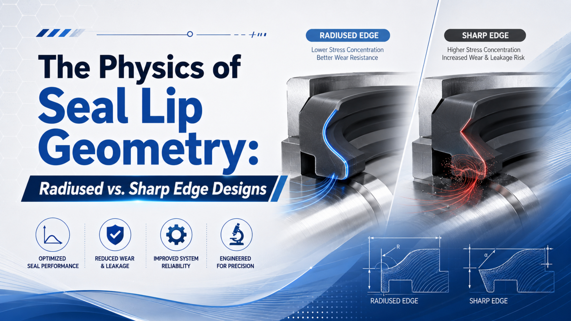
Sharp and radiused edges do different jobs. Used as a wiper, a sharp edge can improve particle removal at the exposed rod without defining the pressure-seal design behind it. Shaped or radiused pressure-seal lips manage contact stress and lubricant movement. Function comes first.
Diagnosis follows function. Rod-end air leakage points toward the pressure seal and mating surface. Debris below the wiper points toward the exposed rod and contamination barrier. One-sided wear moves guidance and side load above lip radius on the fault tree.
Key Takeaways
- Parker rates one pneumatic wiper at 0 bar because wiping and pressure retention are different jobs.
- Radius, angle, material, preload, pressure, surface finish, lubrication, and alignment act together.
- Select the rod seal and wiper as a system, then validate the exact profile under the real duty cycle.
What Does Seal Lip Geometry Actually Control?
Parker rates its E5 pneumatic rod seal for pressures up to 16 bar and speeds up to 1 m/s, but those limits belong to that profile and compound. Lip geometry controls how sealing force is distributed, how the lip responds to pressure, and how it interacts with the moving rod (Parker E5 Rod Seal, accessed 2026).
Seal lip geometry is the working cross-section formed by the contact edge, lip angle, thickness, free diameter, heel, and supporting surfaces. It determines how an installed seal deforms and where contact develops, but it doesn’t replace material data, groove dimensions, pressure direction, or operating-condition limits.
Edge radius is only one part of the cross-section. Lip thickness, angle, free diameter, interference, heel support, material stiffness, groove dimensions, and pressure direction determine how the lip deflects. Rod finish, lubricant, temperature, speed, and alignment then change the contact condition during motion.
Narrow contact bands can create a steeper local pressure distribution, while broader bands spread load over more area. Neither result is automatically better. Too little contact can leak; too much can raise breakaway force, heat, wear, and sensitivity to poor lubrication.
Geometry sets the distribution. It doesn’t set the whole outcome.
An average-pressure relationship helps explain the trend:
Here, is nominal average contact pressure, is total normal load across the lip contact, and is nominal contact area. Use consistent units, such as pascals or newtons per square millimetre. This isn’t a seal-sizing equation because real pressure varies across the contact and normally requires profile-specific analysis or testing.
Friction can be described cautiously as , where is sliding friction and is an effective coefficient for the actual material, surface, lubrication, speed, and temperature. Because that coefficient changes between breakaway and running conditions, a sharper-looking drawing doesn’t prove higher friction by itself.
Instead of asking only whether the edge is sharp or rounded, ask: “What contact-pressure shape, lubricant movement, and contaminant response does this complete profile produce in its installed gland?” The answer connects the drawing to measurable behaviour without treating radius as an isolated specification.
Which Component Has the Edge: Rod Seal, Wiper, or Combined Profile?
Parker lists a maximum operating pressure of 0 bar for its A2 pneumatic wiper and up to 2 m/s rod speed. That single specification exposes the main classification error: the visible lip at the cylinder face may remove contamination without being the component that retains compressed air (Parker A2 Pneumatic Wiper, accessed 2026).
Two definitions prevent confusion. A rod wiper is the contamination-control element at the exposed side of the gland. A rod pressure seal is the dynamic element that retains compressed air around the moving rod. Combined profiles can place both functions in one component, but every lip still needs the correct orientation and supporting geometry.
Names follow functions, not appearance.
Conventional rod-end sealing stacks can contain three distinct functions:
| Component | Primary job | Geometry priority | Evidence of trouble |
|---|---|---|---|
| External wiper or scraper | Remove dust, fibres, water droplets, chips, and residue from the retracting rod | Contaminant exclusion without damaging the rod or stripping all useful lubricant | Debris below the wiper, damaged scraping edge, contaminated gland |
| Rod pressure seal | Retain compressed air while the rod reciprocates | Stable sealing contact with acceptable friction, wear, and lubricant control | Air leakage at the rod end, heat, stick-slip, polished or damaged lip |
| Guide or bearing | Carry permitted transverse reaction and keep the rod aligned | Bearing area, clearance, wear resistance, and load distribution | One-sided polishing, rod scoring, looseness, recurring seal damage |
Some cylinders use a combined seal-wiper instead of separate components. Parker’s EN profile, for example, combines sealing, wiping, and retention functions with two flexible sealing lips and a separate wiper lip (Parker EN Combined Seal-Wiper, accessed 2026). Its multiple edges aren’t interchangeable; each faces a defined direction and task.
That role distinction comes first.
When the leak path is uncertain, compare the symptoms with the dynamic-versus-static cylinder seal guide. It explains why the moving pressure seal, fixed joints, wiper, and guide shouldn’t be diagnosed as one generic seal.
How Do Radius, Angle, and Preload Change Contact Pressure?
Parker’s E5 example pairs a 16 bar pressure limit with a 1 m/s speed limit, yet that datasheet does not reduce selection to one radius value. Contact pressure develops from the installed profile, material, interference, groove, pressure activation, and moving surface as a coupled system (Parker E5 Rod Seal, accessed 2026).
Radius affects how the lip first approaches the rod and how local deformation spreads near the edge. Lip angle influences pressure activation and the direction in which lubricant or contamination is displaced. Preload establishes contact before pressure acts, while flexible lips can gain additional sealing force after pressurization. Material changes that response without changing the outline: softer elastomers can conform to small surface variations but may generate a wider contact patch or greater drag at a given interference, while harder polyurethane profiles may resist abrasion or extrusion differently. Compound, temperature, geometry, finish, and lubricant compatibility still set the result.
The drawing hasn’t changed. The contact mechanics have.
Rod condition matters just as much. Scratches aligned with the stroke can become leakage paths. Rough or damaged surfaces may abrade the lip, while an unsuitable finish can disturb the intended lubricant film. Surface limits should come from the exact seal supplier’s drawing or catalogue, not from a universal number copied across materials. What about a pressure spike at the edge? A local peak can occur, but its magnitude and location need contact analysis or measurement. Pointed drawings aren’t evidence of a particular pressure curve. Ask the supplier for installed cross-sections, finite-element assumptions, friction data, leakage tests, and wear results when the geometry is being used to justify a replacement.
Does a Rounded Lip Always Create a Hydrodynamic Oil Wedge?
No. Parker describes its E9 pneumatic rod seal-wiper set for operation with lubricated air and for oil-free service after initial assembly greasing, with speed limited to 1 m/s. That is not the same as saying every rounded lip rides on a fully developed hydrodynamic oil wedge (Parker Pneumatic Seals Catalogue, accessed 2026).
Pneumatic cylinders often run with a thin lubricant film supplied by factory grease, retained assembly lubricant, material additives, or a controlled upstream lubricator. Film thickness can change during start-up, dwell, reversal, temperature changes, contamination, and long service; at low speed or after a long stop, boundary or mixed lubrication may dominate. Rounded entries can help a profile admit and redistribute lubricant in some designs, and they can reduce a severe geometric discontinuity. Still, oil-wedge formation depends on relative speed, viscosity, contact pressure, surface texture, lip compliance, and available lubricant. Radius alone doesn’t establish the lubrication regime.
Lubrication regime is an operating condition, not a radius label.
Stick-slip also has several causes. Breakaway friction can differ from running friction, but misalignment, oversized preload, dried lubricant, damaged surfaces, low pressure, valve behaviour, and unstable flow can produce similar motion. Before changing lip geometry, work through the air lubrication and seal material guide and confirm whether the cylinder was designed for lubricated or non-lubricated air.
Treat lubricant control as a direction-sensitive function. Pressure seals may need to retain air while leaving a controlled film on the extending rod; the wiper then has to exclude dirt without removing every trace of that film on retraction. One edge cannot be judged without the return path.
When Does a Sharp Wiper Edge Help?
ISO 6195:2021 covers wiper-ring housings for reciprocating rod diameters from 4 to 450 mm. Its scope confirms that wipers are a defined hardware category, but it does not declare one edge shape best for every contaminant, rod surface, speed, or material (ISO 6195:2021, published 2021).
Well-supported scraping edges can remove small, loosely attached particles from a retracting rod. That helps in dirty service. To work without creating a new failure mode, the edge must face the external contamination side and maintain contact without cutting the rod coating, generating excessive drag, or packing fibres beneath the lip.
Different environments need different profiles. Sticky contamination may require a geometry that resists packing beneath the lip; water exposure may require drainage, corrosion control, or a secondary exclusion feature. Metal chips and weld spatter call for guards or bellows because an elastomer wiper isn’t a substitute for physical shielding. Parker notes that a sharp wiper lip can be effective against small contamination, while its rod-wiper guidance also says one design doesn’t fit all applications. Sealing-force relationships between the rod seal and wiper affect whether lubricant returns correctly or escapes (Parker Rod Seal and Wiper Design, accessed 2026).
Some contamination needs hardware beyond the lip.
One-sided polishing or damage should move contamination down the fault tree. Check alignment first. Rod straightness, mounting, guide clearance, and side load can all concentrate contact on one edge; the rod bearing and rod seal failure guide covers that mechanical load path in detail.
Why Must the Rod Seal and Wiper Be Selected Together?
Parker’s E9 set is rated up to 16 bar and 1 m/s and combines a rod seal with a coordinated wiper. The catalogue describes lubricant-retaining geometry because the two components must manage pressure, contamination, friction, and film return together rather than as unrelated catalogue parts (Parker Pneumatic Seals Catalogue, accessed 2026).
During extension, the pressure seal influences how much lubricant remains on the rod. Retraction reverses the problem: the wiper and pressure seal determine what returns to the gland and what stays outside. Direction matters. Excessive scraping may return a nearly dry rod, while permissive wiping can carry contamination toward the sealing interface.
Coordination matters in both directions.
SKF describes both snap-in and double-acting wipers. Some inner-facing lips regulate the lubricant film, while certain seal arrangements need venting to avoid pressure trapped between elements (SKF Hydraulic Seals, 2026). Hydraulic examples shouldn’t be copied directly into pneumatic glands, but they demonstrate why lip direction and inter-seal pressure need deliberate design.
Four questions clarify the complete stack:
| Design check | Required answer |
|---|---|
| Pressure retention | Name the element that retains pressure and its installed direction. |
| Contamination exclusion | Identify the outward-facing edge and the contaminant it must remove. |
| Lubricant movement | Trace the film during extension, retraction, dwell, and start-up. |
| Guidance | Show which bearing carries transverse load and how its clearance is checked. |
Don’t replace one lip by appearance alone. Confirm the cylinder series, drawing revision, groove dimensions, rod diameter and finish, pressure direction, material, lubricant, speed, temperature, and wiper arrangement. Physical fit doesn’t prove functional compatibility.
A Practical Selection Matrix for Seal Lip Geometry
Contrasting Parker’s A2 wiper at 0 bar with its E5 rod seal at up to 16 bar shows why selection starts with component function. Use the matrix below to frame supplier questions; do not treat it as permission to substitute profiles across unverified grooves or compounds (Parker A2; Parker E5, accessed 2026).
Use the matrix as a question set.
| Application condition | Geometry or system question | Evidence to request | Avoid this shortcut |
|---|---|---|---|
| Clean indoor air, smooth motion | How does the installed rod seal manage breakaway, running friction, and lubricant return? | Friction and leakage data at stated pressure, speed, temperature, stroke, and dwell | Assuming a larger radius guarantees smooth motion |
| Dust, fibres, or outdoor grit | Which outward-facing wiper edge removes the expected particle type? | Contamination test, rod compatibility, wiper orientation, inspection interval | Using a sharper pressure-seal lip as the contamination solution |
| Washdown or moisture | Can the wiper exclude liquid and residue, and can the housing drain? | Material compatibility, corrosion plan, ingress test, drainage details | Relying on lip geometry while ignoring the exposed rod and housing |
| High cycle rate | How do heat, film replenishment, and dynamic friction change over the duty cycle? | Temperature, friction, leakage, wear, and endurance results under comparable cycling | Selecting from maximum pressure alone |
| Low pressure or long dwell | Is initial preload sufficient before pressure energizes the lip? | Start-up leakage, breakaway force, relaxation, and low-pressure test data | Checking only normal regulator pressure |
| Side load or misalignment | Is guidance carrying the transverse reaction within clearance limits? | Bearing clearance, alignment, rod runout, wear pattern, mounting review | Installing a harder or sharper seal to mask guide wear |
| Existing non-lubricated service | Which initial grease and material system does the supplier specify? | Assembly instructions, lubricant compatibility, dry-air operating limits | Adding line oil or changing grease without checking compatibility |
In our experience, the fastest seal review starts with photographs before cleaning. Mark the installed orientation, contamination side, pressure side, and clock position. Then compare lip wear with rod scratches, guide polishing, gland residue, and the point in the stroke where friction changes. Cleaning first can erase the failure path.
For unfamiliar kits, use the industrial cylinder seal types guide to identify functional families before comparing material or edge shape. Damage extending to the rod, gland, guide, or bore may shift the decision; the repair-versus-replace framework can prevent repeated seal-only repairs.
Inspection and Replacement Checklist
ISO 6195:2021 spans rod diameters from 4 to 450 mm, so a wiper’s visible edge cannot identify its housing or compatibility by itself. Record the complete installation and duty data before ordering a seal kit, then compare the replacement with the cylinder and seal manufacturer’s current documentation (ISO 6195:2021, published 2021).
Safety comes before inspection.
Before disassembly, isolate every energy source, secure suspended loads, release trapped pressure, and verify the safe state. Trapped air can remain between blocked ports or beneath an external load even after the main supply is shut off.
Use this inspection sequence:
- Identify the path. Locate the leak or contamination entry point.
- Preserve orientation. Photograph the wiper, rod seal, backup elements, guide, pressure direction, and installed clock position before removing or cleaning anything.
- Inspect the rod. Look for axial scratches, corrosion, coating damage, deposits, diameter variation, and one-sided polishing. Record where each mark crosses the seal contact.
- Check guidance. Measure permitted clearance; inspect the bearing, gland, mounting, alignment, and transverse load path.
- Examine every lip. Record cuts, flattening, hardening, softening, swelling, extrusion, uneven wear, packed debris, and lost preload. Compare opposing sides rather than judging the ring after it has been laid flat.
- Verify the groove and lead-in. Compare dimensions and finish with the approved drawing.
- Reconstruct the duty. Record normal and transient pressure, exhaust back pressure, speed, stroke, cycle rate, dwell, temperature, air quality, lubricant history, cleaning chemicals, and recent process changes.
- Match by function and part data. Use the cylinder model, profile, dimensions, compound, orientation, and supplier limits. Ignore color as an identification method.
- Commission under control. Begin at the approved low-risk condition. Check leakage and motion, document the starting state, and inspect again after a defined trial period.
Dry or non-lubricated air requires a review of the limits of self-lubricating cylinder seals. The term can describe different material and lubricant strategies, so it doesn’t eliminate the need for product-specific assembly and service instructions.
Seal Lip Geometry FAQs
Parker’s A2 wiper is listed at 0 bar while its E5 rod seal is listed up to 16 bar, a useful reminder that edge appearance doesn’t define pressure function. These 5 FAQs address sharpness, radius, lubricant films, substitution, and recurring wear without assigning universal limits (Parker A2; Parker E5, accessed 2026).
Is a sharp lip always better at sealing pressure?
No. Pressure sealing depends on the complete installed profile, including material, preload, lip angle and thickness, groove support, pressure activation, surface condition, lubrication, temperature, and speed. A sharp-looking edge may belong to a wiper rated for no pressure, while a differently shaped rod seal retains compressed air.
Does a radiused lip always reduce friction?
No. Radius can influence the contact and lubricant entry, but friction also depends on normal load, material, rod finish, lubricant, temperature, pressure, speed, dwell, and alignment. Compare product-specific breakaway and running-friction data under conditions that match the machine instead of ranking drawings by radius alone.
Is the external wiper the same as the rod pressure seal?
Usually not. A wiper primarily removes external contamination from the retracting rod, while a rod seal retains pressure. Some profiles combine both functions, but their lips still have defined orientations and jobs. Confirm the cylinder drawing and leakage path before deciding which component failed or ordering a replacement.
Can a sharp wiper remove too much lubricant?
Yes, an incompatible or overly aggressive wiper can disturb the film that the rod seal needs, while a weak wiper may allow contamination into the gland. Rod seal and wiper force gradients, materials, orientation, surface condition, and lubricant-return path should be evaluated as one system and validated in service.
Can I replace a radiused seal with a sharper profile?
Only with engineering approval. The review must cover the exact cylinder, groove, rod, pressure direction, compound, lubricant, speed, temperature, and contamination. Physical fit doesn’t prove correct preload, sealing direction, friction, extrusion resistance, or lubricant behaviour. Use manufacturer replacement data or an engineered cross-reference with a controlled validation plan.
Sources and technical references
- ISO 6195:2021, Fluid power systems and components, cylinder-rod wiper-ring housings, current housing-dimension standard covering reciprocating rods from 4 to 450 mm; published 2021, retrieved 2026-07-22.
- Parker Pneumatic Seals Catalogue, PTD3351-EN, E9 rod seal-wiper construction, lubricant-retaining geometry, compound options, installation orientation, pressure and speed limits, temperature conditions, and the distinction between lubricated service and oil-free operation after initial assembly greasing; retrieved 2026-07-22.
- Parker A2 Pneumatic Wiper, external contamination exclusion, 0 bar maximum pressure, and 2 m/s maximum speed for the listed configuration; retrieved 2026-07-22.
- Parker E5 Pneumatic Rod Seal, single-acting rod seal with listed pressure and speed limits; retrieved 2026-07-22.
- Parker EN Combined Seal-Wiper, combined sealing, wiping, and fixing functions with separate lip roles; retrieved 2026-07-22.
- Parker Rod Seal and Wiper Design, wiper geometry, sealing-force gradients, contamination exclusion, and lubricant return; retrieved 2026-07-22.
- SKF Hydraulic Seals, 2026, snap-in and double-acting wipers, lubricant-film regulation, and inter-seal pressure considerations; retrieved 2026-07-22.
- Trelleborg Pneumatic Scraper for Guiding Units, scraper function; retrieved 2026-07-22.