

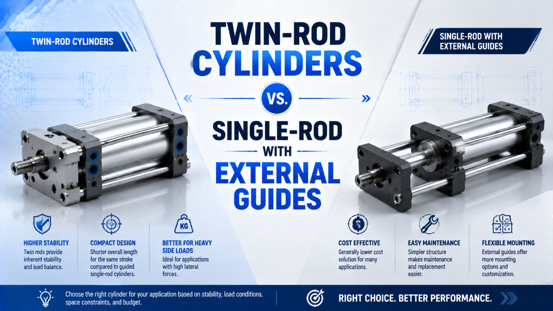
Choose a twin-rod cylinder when a compact, self-contained unit can carry the documented forces and moments. Choose a single-rod cylinder with an external guide when the load needs independently selected guide capacity, stiffness, bearing life, or layout flexibility. Neither architecture wins from payload mass or stroke alone.
The comparison starts with the load path. A twin-rod or compact guided cylinder integrates actuation and some degree of guidance in one body. In an externally guided axis, the cylinder should supply axial drive force while the rail and carriage support the payload, lateral forces, and overturning moments.
Key Takeaways
- SMC CXS2 lists ±0.1° non-rotating accuracy; it does not establish universal side-load capacity.
- Convert mass, acceleration, gravity, process force, and offsets into forces and moments.
- External guides are rated components, not unlimited supports.
- Give the guide one datum and connect the cylinder with an approved compensating joint.
Publisher information is available on the About Us page. Send technical questions or correction requests through Contact.
What Are You Actually Comparing?
SMC’s CXS2 is a dual-rod, double-piston cylinder that states ±0.1° non-rotating accuracy, while Festo’s DFM is a guided drive with separate force and moment ratings. Those examples show why “twin rod” describes geometry, not one universal guiding capacity (SMC CXS2; Festo DFM, 2026).
A twin-rod cylinder is a pneumatic actuator with two parallel rods or piston assemblies constraining a common output plate. An externally guided pneumatic axis is a system in which a separate bearing or rail defines the payload path while the cylinder supplies drive force through a connection designed for the allowed degrees of freedom.
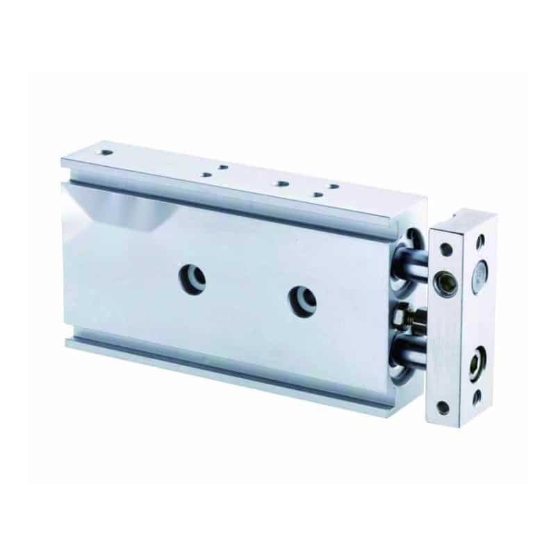
Three product types are commonly mixed together:
-
Twin-rod or dual-rod cylinder: Two parallel rods or piston assemblies constrain a common output plate. The separated supports resist rotation, but allowable transverse load and moment depend on the exact bearing, bore, stroke, speed, and mounting arrangement.
-
Compact guided cylinder or guided drive: A pneumatic drive and a purpose-designed slide or guide are integrated into one product. Manufacturers normally publish axis-specific static and dynamic loads, moments, deflection, kinetic-energy, or service-life information.
-
Single-rod cylinder with an external guide: A standard cylinder drives a payload carriage supported by a separate rail, shaft guide, or bearing system. The cylinder and guide are selected independently and connected without forcing two imperfectly aligned axes to behave as one rigid axis.
The first two types can look similar. Some compact dual-rod cylinders primarily prevent output-plate rotation; others are explicitly rated as guided actuators. Do not infer the second function from two visible rods. Check the product description and the model-specific load data.
Terminology can cause another error. A cylinder with one piston rod extending from both ends is also called a double-rod cylinder in some catalogues. That balanced-area arrangement is different from two parallel rods supporting one output plate.
The hexagonal-rod versus twin-rod mechanics guide covers the internal anti-rotation mechanisms. This article stays with the system decision between an integrated twin-rod arrangement and a separately guided axis.
Load Paths in the Two Architectures
Festo’s DFM catalogue rates , , , , and at the guide centre and requires a combined-load check when several act together. The load path therefore needs a reference point and axes; “20 kg payload” alone cannot establish suitability (Festo DFM, 2026).
In an integrated unit, the output plate transfers payload reactions into its rods, bushings or linear bearings, body, and mounting face. Increasing rod spacing can reduce the opposing bearing forces needed to react one torque, but spacing alone does not provide a rating. Plate stiffness, bearing length, stroke position, mounting flatness, speed, impact, and wear remain part of the system.
In a separately guided axis, the rail controls the payload trajectory. The cylinder rod transfers drive force through a compensating connection. That separation lets an engineer select bore from thrust demand and select the guide from load, moment, stiffness, accuracy, and life requirements.
Separation does not remove interaction. A rigid connection, weak machine plate, excessive guide clearance, or poor alignment can send transverse reaction back through the piston rod. The guide arrangement and connection must make the intended load path physically possible.
How Should You Calculate Force and Moment Demand?
THK bases nominal guide life on basic dynamic load rating and calculated load, and applies additional factors for hardness, temperature, block contact, vibration, and impact. That method confirms that payload mass is only one input; direction, acceleration, distribution, stroke, and duty determine the bearing demand (THK Nominal Life, 2026).
Start with a free-body diagram at the retracted, mid-stroke, and extended positions. Include:
- Payload, gripper, carriage, bracket, hoses, and moving cylinder components.
- Centre-of-gravity offsets from the guide reference point.
- Gravity for the installed orientation.
- Acceleration and deceleration in each direction.
- Process contact forces, cable or hose pull, and expected disturbance loads.
- Normal end stopping and the defined fault-stop case.
For a force acting perpendicular to a guide reference axis, the first moment check is:
Here, is the applied moment in newton-metres, is the perpendicular force component in newtons, and is the perpendicular offset in metres. Resolve pitch, yaw, and roll separately using the selected manufacturer’s coordinate convention.
Dynamic force starts with:
Here, is effective moving mass in kilograms and is acceleration in metres per second squared. Combine it with gravity and process loads as vectors for the governing operating state. Do not add every maximum blindly if the directions or timing cannot occur together; do not omit a credible simultaneous case either.
The cylinder’s available extension drive force can be screened as:
Here, and are absolute or gauge pressures used consistently on the driving and opposing sides, is full piston area, is annular area where applicable, and represents seal, bearing, and connection losses. Measured chamber pressures are preferable to compressor or regulator setpoints.
Consider an illustrative 12 kg moving assembly. During downward deceleration, gravity and a 3 m/s² inertial term act in the same direction. The guide demand in that direction is:
If its centre of gravity is 180 mm from the guide reference:
The result is a demand, not a pass. For a twin-rod or guided cylinder, compare it with the exact model’s applicable moment graph and combined-load rule. For an external rail, distribute the load across the actual blocks, check static safety and dynamic equivalent load, then calculate life using that manufacturer’s method.
The guide does not increase pneumatic thrust. If the axis needs 900 N of drive force after losses, the cylinder still needs to supply that force regardless of whether the payload runs on an integrated guide or an external rail. The cylinder force-loss guide covers the pressure and friction side of that calculation.
When Is a Twin-Rod Cylinder the Better Choice?
SMC’s CXS2 listing states ±0.1° non-rotating accuracy, maximum piston speed of 800 mm/s, and allowable kinetic energy of 0.016 J for that series. These values make a compact unit attractive only when the complete duty stays inside its model-specific limits (SMC CXS2, 2026).
A twin-rod or compact guided cylinder is usually the cleaner starting architecture when:
- The available envelope favours one factory-assembled body and output plate.
- Stroke, payload position, speed, and moment fall inside documented curves.
- Moderate anti-rotation control is required at the output plate.
- Machine assembly would benefit from fewer separate rails, brackets, and alignment interfaces.
- The supplier provides adequate data for the proposed bearing type and duty.
Use the catalogue category accurately. SMC CXS2, for example, is described as a dual-rod cylinder and gives a non-rotating accuracy value. A Festo DFM guided drive publishes static and dynamic forces and moments. The two products should not be credited with identical load-carrying functions simply because both have two visible guide elements.
Compactness also does not guarantee stiffness at the process point. Tooling overhang can amplify a small force into a large moment. The output plate, machine bracket, fasteners, and part fixture can deflect even when the cylinder remains within its rating. Verify loaded displacement at the real tooling datum.
Avoid using the rods as press guides unless the product is rated for the resulting contact force and moment. An insertion tool can experience side force when the parts are not concentric. A separate tooling guide, compliant alignment feature, or externally guided carriage may still be needed.
The strongest reason to choose a twin-rod unit is controlled integration, not an assumed payload threshold. One supplier owns the bore, rods, bearings, plate, body, mounting, and published load method. That can reduce interface risk, but only if the catalogue data actually covers the installed load case.
When Does a Single-Rod Cylinder with an External Guide Make More Sense?
THK defines nominal guide life as the distance that 90% of an identical group can achieve without rolling-fatigue flaking under the same conditions. That statistical definition makes an external guide useful for life-based design, but it also disproves claims of unlimited capacity (THK Nominal Life, 2026).
A separately guided axis is often preferable when:
- Payload forces and three-axis moments need an independently selected guide arrangement.
- The required life, stiffness, preload, accuracy class, or environmental option is unavailable in a compact pneumatic unit.
- A long or unusual stroke makes an integrated guided cylinder impractical.
- The machine needs multiple blocks, widely spaced rails, or a custom carriage.
- The guide and drive need to be serviced or replaced independently.
- The same guided platform may later use a different bore or actuator technology.
External guidance is an architecture, not a single product. Profile rails, round-shaft bushings, cam rollers, plain bearings, and custom ways have different load directions, rigidity, friction, contamination response, lubrication needs, and failure modes.
The guide should be selected from its actual load distribution. A payload centred between two widely spaced blocks behaves differently from the same mass cantilevered outside a single block. THK notes that close multiple-block arrangements can have non-uniform load distribution because of moment loading and mounting-surface accuracy; its contact factors account for that effect.
Static safety and dynamic life are separate checks. A rail can avoid permanent raceway deformation in a stationary overload yet have insufficient fatigue life for millions of loaded cycles. Conversely, a high dynamic rating does not excuse impact that exceeds static limits or damages the carriage, mounting bolts, stops, or machine base.
The price comparison must include the cylinder, rail, blocks, carriage plate, compensating joint, brackets, machining, alignment, lubrication access, guarding, and commissioning. A compact unit may cost more as a component yet less as an installed axis. A separate guide can cost more to assemble yet provide the service life or stiffness the process requires.
How Do You Prevent the Cylinder and Guide from Fighting Each Other?
SMC’s JT floating-joint instructions describe the joint as a coupling for linear reciprocating motion that absorbs slight misalignment, while warning that it is not a rotary coupling and has model-specific eccentricity limits. Compensation must therefore be designed, not assumed (SMC JT, 2026).
An externally guided system contains two nominally parallel motion references: the cylinder rod axis and the guide path. If both are rigidly fixed at every degree of freedom, machining error, assembly tolerance, fastener shift, frame deflection, and thermal growth can make them fight.
Use one functional master. In most arrangements, the guide rail establishes the payload path. Mount the cylinder body squarely enough to transmit thrust, then connect the rod to the carriage through a manufacturer-approved floating joint, self-aligning coupling, clevis arrangement, or purpose-designed compliant bracket.
A compensating connection has limits. SMC states that the JT series is intended for slight misalignment in linear reciprocating motion and warns against rotation or oscillation. It also specifies tightening, allowable eccentricity, impact control, contamination protection, and axial play. The exact joint must be checked like any other load-bearing component.
Commission the assembled axis in stages:
- Verify rail mounting surfaces, reference edges, bolt sequence, and final tightening.
- Move the carriage through the full stroke with the cylinder disconnected or depressurized.
- Check rod-to-carriage offset and angular error at retracted, middle, and extended positions.
- Install the compensating connection without using it to pull misaligned parts together.
- Pressurize gradually and run at reduced speed.
- Record pressure, speed, loaded deflection, abnormal friction, leakage, temperature, and connection movement.
- Repeat the checks at production payload and after thermal stabilization.
The guide-rail parallelism workflow explains how to build a datum-based tolerance budget. The same principle applies here even though the drive is a rod cylinder: one axis should guide, and the other should transmit force without creating a second rigid trajectory.
A Defensible Selection Workflow
Festo’s 2026 DFM data distinguishes static limits from dynamic limits referenced to 10,000 km and then applies a combined-load comparison factor. A defensible comparison must therefore evaluate the same duty against each candidate’s own published method rather than using one universal payload table (Festo DFM, 2026).
-
Freeze the geometry. Define travel, mounting orientation, payload centre of gravity, tooling offsets, process contact points, rail spacing, carriage size, and available envelope at three stroke positions.
-
Define every operating state. Include normal acceleration, deceleration, gravity, process force, end stopping, emergency or fault stopping, pressure loss, hose drag, contamination, temperature, and required cycle count.
-
Calculate force and moment demand. Resolve , , , , , and at the reference point required by each manufacturer. Keep cylinder thrust demand separate from guide reactions.
-
Screen the integrated candidate. Check exact part number, bore, stroke, bearing type, pressure, speed, non-rotating accuracy, allowable loads and moments, kinetic energy, deflection, mounting, and any combined-load equation.
-
Screen the separate system. Size the cylinder for available drive force, rod stability, speed, cushioning, and mounting. Size the rail, blocks, carriage plate, fasteners, and machine base for load distribution, moment, static safety, stiffness, and calculated life.
-
Design the connection and datums. Identify which component guides. Specify the compensating connection, allowable misalignment, axial play, tightening method, and inspection datums.
-
Compare installed consequences. Evaluate total envelope, mass, cost, assembly time, lubrication access, replacement procedure, spare strategy, and fault containment. Avoid comparing one integrated component price with an incomplete bill of materials.
-
Validate the selected axis. Establish acceptance values for loaded deflection, cycle time, pressure, speed, stop behaviour, leakage, alignment, temperature, noise, and inspection intervals. Test the governing operating state rather than only an unloaded slow cycle.
A useful decision rule is: choose the smallest architecture whose complete rated load path remains verifiable. If the integrated product’s catalogue covers every governing load and life requirement, extra guide hardware may add risk without value. If any governing reaction cannot be verified, separate the drive and guidance so each function can be engineered explicitly.
What Information Belongs in the RFQ?
Festo’s DFM data changes permissible loads and moments by piston size, stroke, guide type, static or dynamic condition, and load centre. An RFQ that states only “20 kg, 200 mm stroke” omits the variables needed to choose either architecture (Festo DFM, 2026).
| RFQ field | Information to provide | Why it matters |
|---|---|---|
| Motion | Stroke, orientation, cycle time, speed, acceleration, deceleration | Defines dynamic force, guide load, and stopping energy |
| Moving assembly | Payload, tooling, carriage and bracket masses | Establishes total effective mass |
| Load geometry | Centre-of-gravity offsets and process-force coordinates | Converts forces into pitch, yaw, and roll moments |
| Pneumatics | Minimum cylinder pressure, back pressure, bore, rod, valve and tubing | Determines available drive force and speed |
| Integrated candidate | Exact series, bearing option, stroke and mounting | Identifies the controlling load charts |
| External guide | Rail and block model, quantity, spacing, preload and accuracy | Determines load distribution, stiffness, and life |
| Connection | Floating-joint model, allowed offsets, angle, play and tightening | Prevents over-constraint and defines positioning effects |
| Environment | Dust, washdown, chemicals, temperature and lubrication access | Changes seals, guide type, protection and maintenance |
| Acceptance | Required life, deflection, angular error, repeatability and test load | Turns “precision” into measurable requirements |
Ask each supplier to return the exact configured drawing, coordinate convention, load reference point, allowable loads and moments, combined-load method, life basis, installation instructions, maintenance requirements, and exclusions.
Do not request “SMC-compatible” or “Festo-compatible” without an existing part number and interface drawing. Matching bore and stroke do not prove identical rod spacing, mounting holes, ports, sensors, output-plate height, load rating, or service parts.
Twin-Rod and External-Guide FAQs
SMC publishes ±0.1° non-rotating accuracy for CXS2, while Festo’s DFM publishes five separate force and moment terms. The two specifications answer different questions, which is why a buyer should not reduce this choice to payload mass, stroke, or one precision number (SMC; Festo, 2026).
Can a twin-rod cylinder replace an external linear guide?
It can when the exact cylinder is rated for every applied force, moment, speed, energy, deflection, and life requirement. Two rods prevent free rotation but do not prove unlimited lateral capacity. If the catalogue lacks a governing load case or the tooling needs independent stiffness and life selection, use a rated guided drive or external guide.
Does an external guide improve pneumatic-cylinder force?
No. The rail changes the reaction path but does not increase piston area or effective pressure. Cylinder thrust still depends on the pressure difference, piston and rod areas, friction, back pressure, and flow conditions. The external guide should support payload forces and moments so the piston rod can transmit primarily axial drive force.
Is a twin-rod cylinder more accurate than a guided single-rod system?
Not as a universal rule. SMC’s ±0.1° CXS2 figure describes non-rotating accuracy, not complete machine positioning accuracy. An external guide has separate running accuracy, stiffness, preload, and life specifications, while the pneumatic axis also has seal friction, compressibility, end-stop variation, connection play, and structural deflection.
How much misalignment can a floating joint absorb?
Use the exact joint’s eccentricity, angle, axial-play, load, and tightening limits. SMC describes JT as absorbing slight linear misalignment and warns against rotation or oscillation. A floating joint cannot correct a distorted rail, weak bracket, major axis error, or connection geometry that forces it against its travel limit.
Which option lasts longer?
Whichever complete system has adequate rated margin, alignment, lubrication, impact control, contamination protection, and maintenance for the duty. THK expresses rolling-guide life statistically from dynamic load and calculated load; Festo ties guided-drive dynamic ratings to a reference distance. Neither supports a universal service-life advantage from architecture alone.
Sources and technical references
- SMC CXS2 Dual Rod Cylinder. Evidence role: double-piston construction, ±0.1° non-rotating accuracy, speed, kinetic energy, bores, and bearing options. Source type: manufacturer product catalogue; accessed July 27, 2026.
- SMC CXSJ/CXSW Dual Rod Cylinder Catalogue. Evidence role: bearing-dependent product data, plate deflection, maximum load mass, non-rotating accuracy, and kinetic-energy guidance. Source type: manufacturer catalogue; accessed July 27, 2026.
- Festo Guided Drives DFM. Evidence role: force and moment axes, static and dynamic limits, combined-load factor, centre-of-gravity calculation, and service-life reference. Source type: manufacturer data sheet; May 2026.
- THK LM Guide Nominal Life. Evidence role: nominal-life definition, dynamic load rating, calculated load, contact factor, and vibration or impact factors. Source type: manufacturer engineering guidance; accessed July 27, 2026.
- SMC JT Floating Joint. Evidence role: intended misalignment compensation, mounting, eccentricity, impact, contamination, and use limitations. Source type: manufacturer catalogue and precautions; accessed July 27, 2026.
- Parker OSP-P Catalogue. Evidence role: clevis connection for parallelism compensation when a pneumatic drive is used with an external guide. Source type: manufacturer catalogue; accessed July 27, 2026.