

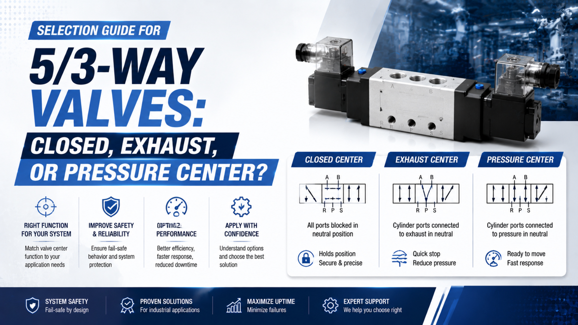
Selecting a closed, exhaust, or pressure center 5/3-way valve starts with the machine state you must prove, not a preferred spool label. Closed center traps air, exhaust center opens both actuator ports to exhaust, and pressure center supplies both ports. None of those conditions alone guarantees load holding, safe access, or controlled restart.
A reliable selection separates normal neutral from electrical power loss, pilot-pressure loss, supply-air loss, and repressurization. Measure the actuator response in each state. If the decision is based only on the middle box of a valve symbol, the circuit review isn’t finished.
Key Takeaways
- SMC lists 3 distinct center functions: closed, exhaust, and pressure.
- Closed center can drift; exhaust center can permit load-driven movement.
- Equal pressure on a single-rod cylinder creates unequal opposing forces.
- Validate 5 states, including power loss and repressurization, before approval.
What Should a 5/3-Way Valve Center Selection Decide?
SMC catalogs 3-position valves as three separate center functions: closed, exhaust, and pressure (SMC VFA1000/3000/5000 catalog, retrieved 2026-07-27). The selection must define the installed actuator’s measurable neutral behavior, not merely repeat the catalog name. Port routing, load direction, and the valve’s centering mechanism must be reviewed together.
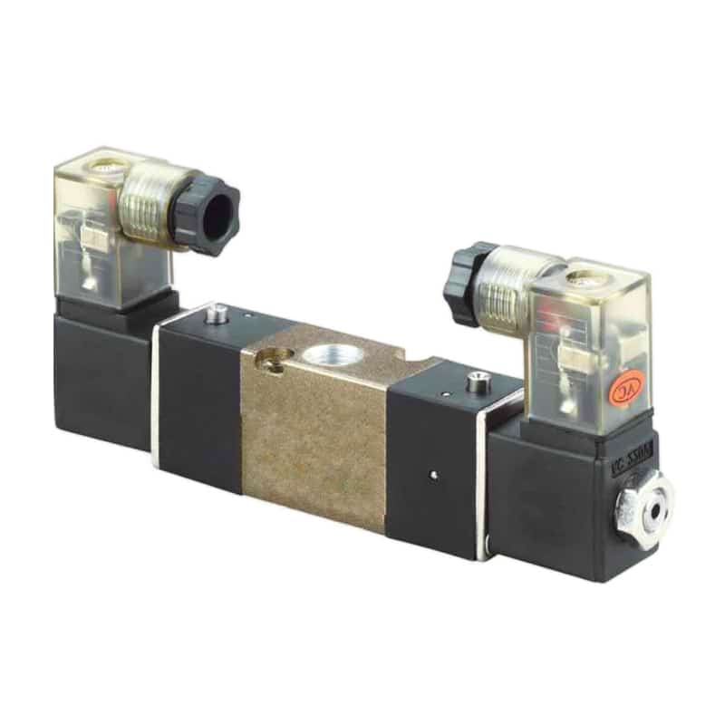
A 5/3 directional valve has five main ports and three spool positions. Port 1 is normally pressure supply, ports 2 and 4 serve the actuator, and ports 3 and 5 are exhaust paths. The two outer positions drive a double-acting actuator in opposite directions. The middle position determines which of those ports are connected or blocked.
That middle box still doesn’t tell you everything. You also need to know whether the valve is spring-centered, pressure-centered, directly operated, or pilot operated. Internal or external pilot supply matters. So do manifold pressure zones, common exhausts, manual overrides, flow controls, check valves, and the load attached to the cylinder.
The broader guide to 3-position valve center conditions explains the three flow patterns. This guide focuses on the next engineering step: proving what the selected center does during a neutral command, a fault, and a restart.
Read the center box, then verify the part code
ISO 11727 covers identification of pneumatic valve ports, flow paths, controls, and solenoid leads (ISO 11727:1999). Read the middle box of the three-position symbol, then confirm the complete ordering code in the manufacturer’s current catalog.
| Center function | Supply port 1 | Working ports 2 and 4 | Intended neutral condition |
|---|---|---|---|
| Closed center | Blocked | Blocked | Air is trapped in both actuator lines |
| Exhaust center | Blocked | Connected to exhaust ports 3 and 5 | Both actuator lines are depressurized through the valve |
| Pressure center | Connected | Both connected to pressure | Both actuator lines remain supplied |
Ordering letters aren’t universal. A familiar suffix from one manufacturer can mean something different in another series. Matching the body size, connector, or mounting pattern doesn’t prove the replacement has the same spool, pilot arrangement, flow capacity, or failure response.
How Much Position Holding Can Closed Center Provide?
SMC states that accurate intermediate stopping is difficult because air is compressible and that valves and cylinders aren’t guaranteed zero leakage (SMC VQ100 precautions, retrieved 2026-07-27). Closed center can pause an axis, but it isn’t a zero-drift mechanical lock. Treat drift as a measured acceptance limit.
Closed center is a neutral flow condition that blocks the normal supply and exhaust paths. Air trapped in the cylinder chambers behaves like two pneumatic springs. External force can compress one chamber and expand the other, while seal leakage, valve leakage, fitting leakage, temperature change, and tube expansion alter pressure over time.
How long will the cylinder stay inside its allowed position band? A catalog symbol cannot answer that. Define the load direction, dwell time, acceptable drift, starting position, chamber pressures, temperature range, and permitted leakage. Then measure position and both port pressures through the complete dwell.
Repeat the test after approaching neutral from both powered directions. The pressure distribution can differ depending on which chamber was supplied immediately before centering. A circuit that holds acceptably after extension may drift or jump after retraction.
For a suspended, vertical, or hazardous load, use a rated mechanical restraint or another validated load-holding method. The cylinder rod-lock guide explains why trapping air and mechanically restraining motion solve different problems. A normal directional valve should not carry the safety claim by itself.
When Does Exhaust Center Produce a Usable Depressurized State?
SMC warns that manifold backpressure can cause actuator malfunction and calls for specific exhaust measures in affected circuits (SMC VQ100 precautions, retrieved 2026-07-27). Exhaust center creates an exhaust path, but restrictions determine how quickly pressure actually disappears at the cylinder. Measure the decay at both working ports.
Exhaust center is a neutral flow condition that blocks the supply port while connecting both working ports to exhaust. That can support manual repositioning or allow an external spring or gravity load to move the mechanism. It can also release a clamp, drop a vertical axis, or expose an operator to stored mechanical energy.
“Free floating” is an intention, not a measured result. Meter-out controls, clogged silencers, long tubing, cylinder cushions, pilot-operated checks, seal friction, misaligned guides, and external stops can resist motion. A nearby quick exhaust valve changes the pressure-decay path again.
Record pressure at both cylinder ports from the neutral command until the specified residual-pressure threshold is reached. Repeat with the most restrictive credible exhaust condition. If a muffler can clog in service, include that fault or define a maintenance limit that prevents it.
Do you expect gravity or a spring to return the axis? Measure that movement with the real load, speed controls, guards, and end stops installed. Exhaust center doesn’t create a controlled retract profile automatically, and it doesn’t turn a standard directional valve into a monitored safety exhaust device.
Pressure Center Force Is Set by Effective Area
SMC’s cylinder-selection data treats extension and retraction as separate force cases because the effective areas differ (SMC Air Cylinders Model Selection, retrieved 2026-07-27). Supplying both chambers at equal pressure therefore does not create equal opposing forces on a typical single-rod cylinder. Bore, rod diameter, and external load determine the bias.
Pressure center is a neutral flow condition that supplies both working ports while blocking their normal exhaust paths. Use the installed port pressures and effective areas:
Here, is the signed axial force in newtons, and are the measured cap-end and rod-end gauge pressures in megapascals, and are effective areas in square millimetres, and is the external load opposing extension. The equation omits friction and dynamic pressure loss.
For a bore diameter and rod diameter :
Consider a 50 mm bore, a 20 mm rod, and 0.6 MPa in both chambers. The pressure-center bias before load and friction is:
The result is about 188 N toward extension because the area difference equals the rod cross-sectional area. Real pressure can differ between ports because of valve geometry, flow, leakage, supply loss, and load motion, so measure both ports instead of substituting regulator pressure.
Pressure center can increase pneumatic stiffness in a particular circuit, but “stiffer” doesn’t mean balanced, locked, or safe. It also doesn’t imply continuous full-flow consumption while stationary. Make-up flow occurs during initial filling, movement, or leakage. Measure neutral leakage if air use matters.
Five Fault States That Must Be Tested Separately
ISO 4414 applies to pneumatic-system design, installation, adjustment, operation, and maintenance, and addresses significant system hazards rather than one valve label (ISO 4414:2010). A useful center-state validation therefore separates 5 conditions that are often collapsed into the phrase “when power is lost.”
- Commanded neutral: Both directional commands are intentionally removed while electrical power, pilot pressure, and main supply remain available.
- Coil or output power loss: Electrical energy disappears, but pneumatic supply and pilot pressure may remain.
- Pilot-pressure loss: A pilot-operated valve may fail to shift or center even though the controller output changes correctly.
- Main-supply loss: Cylinder pressure decays through leakage or exhaust paths while gravity and stored mechanical energy remain.
- Repressurization and restart: Supply returns when the spool, actuator, controller state, and trapped chamber pressures may not match.
The restart test frequently exposes a failure that a neutral dwell hides. An axis may stay nearly still while centered, then jump when one chamber reconnects to supply and the other reconnects to exhaust. Set a maximum permitted restart displacement and require position confirmation before automatic motion resumes.
How Should the Center State Be Commissioned?
SMC explicitly says a closed-center valve isn’t suitable as an emergency shut-off valve and calls for separate residual-pressure release provisions (SMC VQ100 precautions, retrieved 2026-07-27). Commission the center state at controlled energy, with the real actuator, load, exhaust devices, sensors, and restraints installed.
Before testing, define acceptance limits for neutral drift, pressure-decay time, residual pressure, load movement, restart displacement, and sensor validity. “No obvious movement” isn’t a test result. Use calibrated pressure sensors at ports 2 and 4 and an independent position measurement appropriate to the permitted error.
Run the following sequence from both powered directions:
- Verify the valve part code, middle-box symbol, coil arrangement, spring centering, pilot source, exhaust arrangement, and manual-override state.
- Command one powered position, establish the specified load and speed, then remove both commands.
- Log cap-end pressure, rod-end pressure, actuator position, and time through the full neutral dwell.
- Repeat after approaching center from the opposite powered position.
- Remove electrical power while maintaining air, then compare the response with commanded neutral.
- Remove pilot pressure separately if the valve is pilot operated.
- Isolate main supply and observe pressure decay and load-driven movement.
- Restore pressure through the real startup valve or soft-start path, then verify that motion remains within the restart limit.
- Repeat credible exhaust restrictions, sensor failures, and stuck manual-override conditions identified by the risk assessment.
In our experience, the most useful commissioning record places valve commands, both chamber pressures, and actuator position on one time base. That immediately separates spool-state problems from cylinder leakage, exhaust restriction, load motion, and controller sequencing. A single pressure gauge at the regulator can’t provide that diagnosis.
| Observed result | Likely mechanism | First check |
|---|---|---|
| Drift in closed center | Valve or cylinder leakage, compliance, external load, temperature | Trend both chamber pressures and position |
| Residual pressure in exhaust center | Meter-out control, silencer, check valve, small tubing, blocked exhaust | Measure at ports 2 and 4, not only at the valve supply |
| Extension bias in pressure center | Unequal effective areas or unequal port pressures | Calculate net force and measure both pressures |
| Valve doesn’t center after power loss | Incorrect spool, pilot dependency, stuck spool, override, wiring state | Confirm part code, spring/pressure centering, pilot circuit |
| Jump during restart | Unequal trapped pressure or invalid actuator position | Log pressure and position before and after repressurization |
The solenoid-valve response-time guide is useful when the acceptance limit depends on the delay between command removal, spool shift, port-pressure change, and actuator response.
Which Center Function Should You Approve?
SMC’s VFA catalog treats closed, exhaust, and pressure center as distinct ordering choices, while ISO 4414 requires the pneumatic system to address its significant hazards (SMC VFA catalog; ISO 4414). Approve the option that passes the machine-state acceptance test, not the one with the most reassuring label.
| Required neutral result | Candidate to evaluate | Acceptance evidence | Additional measure often required |
|---|---|---|---|
| Temporary process pause within a drift band | Closed center | Position and both pressures remain within limits for the full dwell | Mechanical restraint for hazardous or suspended loads |
| Intentional depressurization of both actuator lines | Exhaust center | Both ports reach the residual-pressure limit within the required time | Separate control of gravity, spring, or stored-energy motion |
| Both lines remain charged | Pressure center | Measured pressures and calculated net force produce acceptable motion | Restraint or control for single-rod force bias |
| Safe emergency-stop response | Application-specific architecture | Validated stop, load restraint, energy state, diagnostics, and reset | Safety-rated components selected from the risk assessment |
| Predictable restart | Any center, if proven | Repressurization and command recovery stay inside movement limits | Soft start, position validation, controlled reset, or brake |
Closed center is a reasonable candidate when a nonhazardous axis needs a short pause and measured drift is acceptable. Exhaust center is a candidate when both lines must vent and load-driven movement is controlled elsewhere. Pressure center is a candidate when both lines must remain energized and the resulting force bias is understood.
None is a universal emergency-stop answer. Exhausting can release a clamp. Trapping air preserves stored energy. Supplying both sides keeps energy present. The ISO 13849 pneumatic safety-circuit guide explains why the complete safety function needs its own architecture, diagnostics, and validation.
What Must Be Included in the Valve Specification?
ISO 11727 standardizes identification concepts, but the final specification still needs the manufacturer’s complete ordering data and the machine’s required response (ISO 11727:1999). At minimum, record 12 items so purchasing cannot substitute a mechanically similar valve with different neutral behavior. Treat the center symbol as controlled RFQ data.
- Manufacturer, series, and complete ordering code.
- Five-port, three-position symbol with the exact middle-box connections.
- Closed, exhaust, or pressure-center wording from the selected catalog.
- Solenoid, air-pilot, spring-centering, or pressure-centering arrangement.
- Internal or external pilot supply and the permitted pilot-pressure range.
- Supply, working, and exhaust port sizes and thread standards.
- Required flow capacity and permitted pressure range.
- Exhaust arrangement, silencer, flow-control, and backpressure limits.
- Coil voltage, frequency where applicable, connector, suppression, and duty.
- Actuator type, bore, rod diameter, stroke, load direction, and speed.
- Acceptance limits for drift, residual pressure, load motion, and restart displacement.
- Required behavior for commanded neutral, electrical loss, pilot loss, supply loss, and repressurization.
Don’t accept “direct replacement” as the technical specification. Compare the center symbol, pilot logic, electrical interface, flow data, leakage statements, mounting interface, pressure limits, exhaust routing, and approved application. A replacement passes only when the installed circuit repeats the required measurements.
5/3-Way Valve Center Selection FAQs
SMC identifies 3 separate 5/3 center functions, while its application precautions warn that closed-center circuits can leak and exhaust paths can be affected by backpressure (SMC VFA catalog; SMC precautions). These answers cover the field checks most likely to prevent a wrong substitution in service.
Can a closed-center 5/3-way valve safely hold a vertical load?
Not by itself. Closed center can trap air and slow movement, but leakage, compressibility, temperature change, and external load can still cause drift. A suspended or hazardous vertical load normally needs a separately rated mechanical restraint plus a validated control sequence, residual-energy procedure, reset, and restart test.
Does exhaust center guarantee that a cylinder is safe to move by hand?
No. It connects both working ports to exhaust, but residual pressure can remain behind flow controls, checks, silencers, or restricted tubing. Gravity, springs, tooling, and counterweights may also move the mechanism. Isolate energy, measure pressure at both actuator ports, and secure the load before manual intervention.
Does pressure center consume air continuously in neutral?
Not as continuous full flow in a stationary, sealed circuit. The valve initially fills both actuator lines and supplies make-up air for leakage or movement. Actual consumption depends on valve, cylinder, fitting, and tube leakage plus any resulting actuator motion, so measure neutral flow under the installed pressure and temperature.
Why can a single-rod cylinder move when both ports have equal pressure?
Force equals pressure multiplied by effective area. The cap end acts on the full piston area, while the rod end acts on the smaller annular area. Equal chamber pressure therefore creates a net extension bias before external load, seal friction, guide friction, and dynamic pressure differences are included.
What is the most important restart test for a 5/3 valve?
Approach center from each powered direction, record both chamber pressures and position, then restore supply and commands through the real startup sequence. Measure the first unintended movement before feedback becomes valid. This catches pressure imbalance, incorrect spool state, pilot dependency, and controller assumptions that a neutral dwell alone can miss.
Sources and technical references
SMC: Series VFA1000/3000/5000 5 Port Air Operated Valve, 3-position closed-, exhaust-, and pressure-center functions, symbols, port sizes, and operating data. Retrieved 2026-07-27.
SMC: VQ100 Application Guidance, intermediate-stop, leakage, backpressure, residual-pressure, and emergency-shutoff cautions. Retrieved 2026-07-27.
SMC: Air Cylinders Model Selection, separate extension and retraction force treatment and cylinder effective-area selection. Retrieved 2026-07-27.
ISO: ISO 11727:1999, identification of pneumatic valve ports, flow paths, controls, and solenoid leads. Retrieved 2026-07-27.
ISO: ISO 4414:2010, general rules and safety requirements for pneumatic systems and components. Retrieved 2026-07-27.