

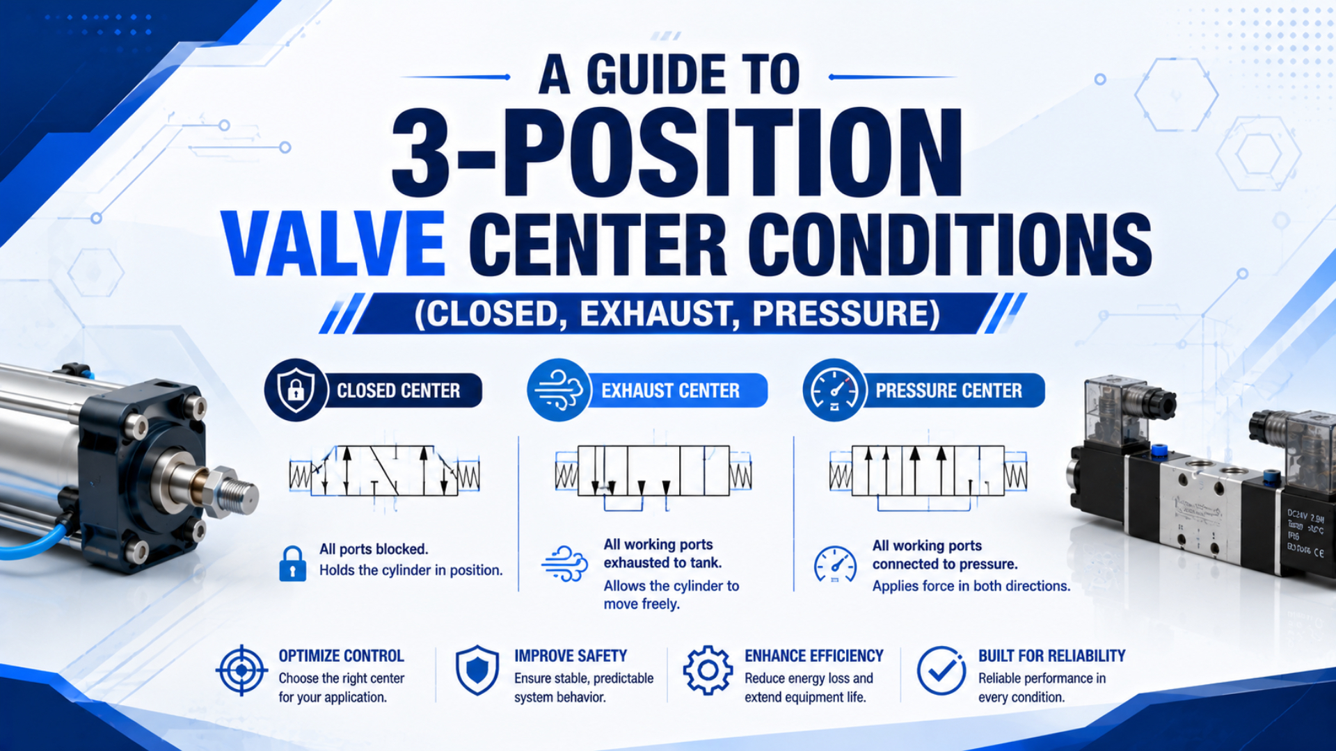
The center condition of a 5/3 pneumatic valve determines what happens to its five ports when the spool returns to the middle position. Closed center blocks the working paths, exhaust center vents both actuator ports, and pressure center supplies both actuator ports. None of those states automatically guarantees exact position holding or machine safety.
Choose the center function from the required neutral-state behavior, external load, actuator geometry, exhaust restrictions, and restart sequence. Then verify the actual symbol and ordering code. Two valves can share the same body, coils, and port sizes while producing very different motion after electrical power or control signals disappear.
Key Takeaways
- A 5/3 valve has five ports, three spool positions, and one center flow pattern that must match the machine state.
- Closed center traps air, exhaust center removes actuator pressure, and pressure center energizes both chambers.
- None of the three replaces a risk-assessed holding device, emergency-stop function, or controlled restart sequence.
What Does the Center Position of a 5/3 Valve Control?
A 5/3 valve has five ports and three switching positions. SMC publishes separate working-principle views for closed-, exhaust-, and pressure-center 3-position valves (SMC SY working principle, retrieved 2026). The center box on the circuit symbol decides which neutral flow path the selected valve uses.
The five common connections are one supply port, two actuator ports, and two exhaust ports. Typical numeric labels are 1 for supply, 2 and 4 for working ports, and 3 and 5 for exhaust. ISO 11727 establishes identification rules for pneumatic valve ports and control mechanisms, but the selected manufacturer’s drawing remains the installation authority (ISO 11727:1999).
The two end positions of a normal 5/3 valve reverse a double-acting actuator. One end connects supply to one chamber while the opposite chamber exhausts. The other end reverses those paths. The center position adds a third machine state after both solenoid commands turn off or the centering mechanism acts.
Center condition is the internal port connection that exists in the valve’s neutral or middle spool position. It isn’t the same as a bistable valve that retains its last SET or RESET state. The related pneumatic latching circuit guide explains that separate memory function.
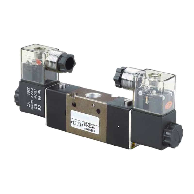
A valve body photograph doesn’t prove whether the center is closed, exhausted, or pressurized. Read the center box of the printed symbol and verify the complete part number. Coil count only shows how the spool is actuated, not what passages connect in neutral.
Three Center Conditions at a Glance
SMC’s VFA3000/5000 catalog lists three distinct 3-position functions: closed center, exhaust center, and pressure center (SMC VFA3000/5000, retrieved 2026). The useful comparison is not the label alone. It is the commanded path through ports 1, 2, 3, 4, and 5.
| Center function | Supply port 1 | Working ports 2 and 4 | Exhaust ports 3 and 5 | Typical actuator consequence |
|---|---|---|---|---|
| Closed center | Blocked | Blocked | Blocked | Air is trapped in the actuator lines; drift and elastic movement remain possible |
| Exhaust center | Blocked | Connected to exhaust | Open to working ports | Actuator becomes unpowered and can move under load, gravity, or manual force |
| Pressure center | Connected to both working ports | Both pressurized | Blocked | Both chambers are energized; force balance depends on effective areas and load |
The diagram is functional, not a substitute for the selected product symbol. Some valve families use different exhaust arrangements, external pilot supplies, pressure zones, or reversible flow. What matters is the center box supplied with the exact ordering code.
Closed Center: A Pause, Not a Mechanical Lock
SMC identifies closed center as one of three distinct 5-port, 3-position functions in its VFA3000/5000 family (SMC VFA3000/5000, retrieved 2026). Its center symbol blocks the supply, working, and exhaust paths. That stops commanded flow, but it doesn’t eliminate leakage or air compliance.
Closed center is a neutral flow pattern that traps air in the cylinder chambers, tubes, fittings, and valve passages. Those volumes behave like pneumatic springs, so external load, temperature, seal friction, and unequal chamber pressure can move the piston even while the spool is centered. SMC warns that accurate intermediate stopping is difficult because compressed air is compliant and valves plus cylinders aren’t guaranteed to have zero leakage (SMC VQ100 guidance, retrieved 2026). Closed center therefore fits only a defined, nonhazardous pause after machine testing establishes acceptable drift, dwell, and restart movement. It isn’t a positive lock, maintenance support, or proof of zero air consumption.
The key design question is not “Does the valve block all five ports?” It is “How far may the actuator move, for how long, and what happens when the spool leaves center again?” A valid acceptance test records chamber pressure, position, load, dwell time, and the first restart movement.
Closed center also doesn’t prove minimum energy use. Neutral flow may be low, but leakage, pilot consumption, repeated repressurization, and the energy used to refill exhausted chamber volume still belong in the system total. Compare measured air demand over the complete machine cycle instead of assigning an efficiency rank from the center symbol.
For detailed drift, trapped-pressure, and holding-method analysis, use the focused guide on 5/3 closed-center cylinder position holding. That article also distinguishes temporary pneumatic holding from pilot-operated checks, rod locks, and mechanical stops.
Exhaust Center: Low Resistance, Not Automatic Safety
In the exhaust-center function shown by SMC, working ports 2 and 4 connect to exhaust ports 3 and 5 while supply port 1 is blocked (SMC VFA3000/5000, retrieved 2026). The cylinder becomes unpowered, so gravity, process force, springs, or manual force can move it.
Exhaust center is a neutral flow pattern that removes the normal pressure path and opens both actuator chambers to exhaust. It can support manual repositioning or a controlled relax state, but it also permits load-driven movement. Residual pressure and stored mechanical energy still require separate verification.
That behavior can be useful when tooling must be repositioned manually after energy isolation, or when an actuator should relax instead of trapping pressure. It can also create a new hazard. A vertical axis may drop, a clamp may release, and a suspended mechanism may move as soon as chamber pressure decays.
Exhaust center doesn’t guarantee instant depressurization. Small tubing, meter-out controls, mufflers, pilot-operated checks, and clogged exhaust devices can retain pressure. A nearby quick exhaust valve changes the exhaust path again, so the final state must be tested at the actuator rather than inferred at the manifold.
Would an operator really be able to move the cylinder freely? Only if the mechanical load, seals, guides, cushions, checks, and exhaust restrictions allow it. “Free float” is a circuit intention, not a universal result.
Use exhaust center when the required neutral state is an unpowered actuator and the risk assessment accepts or separately restrains the resulting movement. Don’t select it merely because a specification contains the words “emergency stop.”
Pressure Center: Both Chambers Remain Energized
Pressure-center 5/3 valves connect supply to both working ports while blocking the exhaust paths in the middle position. SMC lists this as a separate pressure-center function and provides a matching working-principle view (SMC VFA3000/5000; SMC SY working principle, retrieved 2026). Both actuator chambers remain energized.
Pressure center is a neutral flow pattern that supplies both actuator chambers. Equal pressure can approximately balance a double-rod cylinder with equal effective areas before load and friction are included. It cannot balance a typical single-rod cylinder because the cap-end area is larger than the rod-side annular area, creating unequal opposing forces. Pressure center can increase pneumatic stiffness, keep both lines filled, or reduce part of the fill delay in a specific circuit, but it doesn’t automatically produce the fastest cycle or highest useful force. Switching still depends on spool response, flow capacity, tube volume, exhaust resistance, and load. Static pressurization also isn’t continuous full-flow consumption; refill demand comes from initial filling, leakage, or movement.
Pressure center is the easiest option to misread on a schematic. Two equal pressure arrows look balanced, yet force depends on pressure multiplied by effective area. Always add actuator geometry and load direction to the center-condition review. The valve symbol alone cannot predict the neutral motion of a single-rod axis.
Which Center Condition Matches the Required Neutral State?
The three center functions change five-port routing, but no center condition is “best” in isolation. ISO 4414 covers pneumatic-system hazards, reliable operation, installation, maintenance, and unintended behavior across the whole circuit (ISO 4414:2010, confirmed 2021). Select the valve from the documented machine response.
| Required neutral behavior | Candidate center | Why it may fit | Main limitation to resolve |
|---|---|---|---|
| Pause a nonhazardous axis for a defined dwell | Closed center | Blocks commanded supply and exhaust paths | Leakage, compliance, drift, and restart jump remain possible |
| Allow an unloaded mechanism to be repositioned manually | Exhaust center | Vents both working chambers | Gravity or external load may move the actuator unexpectedly |
| Remove actuator pressure after a normal control command | Exhaust center | Provides a defined exhaust path through the directional valve | Back pressure and downstream checks can delay venting |
| Keep both actuator lines pressurized in neutral | Pressure center | Maintains pressure in both chambers | Single-rod area difference creates unequal force |
| Hold a suspended or hazardous load | None by itself | A center valve can support the control strategy | Use a rated brake, rod lock, stop, blocking method, or other validated restraint |
| Perform an emergency stop | Application-specific safety function | The center state may be one subsystem response | Risk assessment and validation decide whether to vent, retain, brake, or combine actions |
Start with three questions:
- What mechanical movement is acceptable in neutral?
- What happens when supply pressure disappears?
- What happens when pressure returns?
If any answer depends on “the cylinder probably stays where it is,” the specification is incomplete.
Then separate production control from maintenance and safety. A center state used for a one-second process pause may be unsuitable for operator access or maintenance support. If a physical lock is required, compare it with the latching-cylinder design guide rather than asking a spool valve to make a mechanical holding claim.
How Do You Identify and Specify the Center Function?
ISO 11727 covers identification of pneumatic directional-valve ports, flow paths, controls, and solenoid leads (ISO 11727:1999). For a 5/3 valve, read all three boxes in the symbol and focus on the middle box. A matching body and connector do not prove matching center flow.
Use this identification sequence:
- Record the complete manufacturer, series, and ordering code.
- Confirm that the symbol has five ports and three spool-position boxes.
- Trace supply port 1, working ports 2 and 4, and exhaust ports 3 and 5 in the center box.
- Verify spring centering, solenoid or pilot arrangement, and the state produced when commands disappear.
- Check whether pilot supply is internal or external and whether pilot exhaust is common or separate.
- Review operating pressure, pilot pressure, flow data, permitted back pressure, leakage, mounting, and manual overrides.
- Put the exact symbol and center-function wording on the RFQ and machine schematic.
Ordering letters such as C, E, or P are common but not universal. Don’t translate one manufacturer’s suffix into another supplier’s part number without checking the catalog. Even within one family, sub-base routing, pressure zones, or external-pilot options can change how the installed valve behaves.
The general 4-way 5-port valve guide explains P, A, B, EA, and EB routing in the two powered positions. Keep this center-condition article focused on the third state and the transition into and out of it.
Commissioning the Center State and Restart Behavior
ISO 4414 applies to pneumatic-system design, construction, modification, installation, adjustment, operation, and maintenance (ISO 4414:2010). A useful center-state test therefore covers more than de-energizing the coils. It proves pressure, position, load response, and restart from both powered directions.
Test the circuit at reduced and controlled energy before full production:
- Verify the installed ordering code and symbol against the approved drawing.
- Command position 12, remove both commands, and confirm the spool centers.
- Record pressure at both working ports and actual actuator movement through the full dwell.
- Repeat from position 14 because the trapped or residual pressure can be different.
- Isolate supply and observe load movement as pressure decays.
- Restore supply from every possible center and actuator state.
- Test blocked or restricted exhaust, failed position sensing, and manual override recovery.
- Confirm the controller does not resume automatic motion until the real actuator position is valid.
| Symptom | Likely center-state mechanism | First diagnostic check |
|---|---|---|
| Cylinder drifts in closed center | Valve, fitting, or cylinder leakage; external load; air compliance | Log both chamber pressures and position during dwell |
| Cylinder won’t move freely in exhaust center | Restricted exhaust, meter-out valve, check valve, cushion, or mechanical friction | Measure residual pressure at ports 2 and 4 |
| Single-rod cylinder creeps in pressure center | Unequal effective areas or unequal chamber pressures | Compare cap-end and rod-side pressure plus load direction |
| Axis jumps when a command returns | Trapped or precharged pressure was unequal | Record pressure immediately before and after switching |
| Valve doesn’t center after power loss | Wrong valve function, stuck spool, pilot issue, or manual override | Confirm ordering code, centering mechanism, and pilot supply |
The restart test often reveals more than the neutral dwell. A circuit can appear stable for several seconds, then jump when the spool reconnects one chamber to supply and the other to exhaust. Specify maximum permitted restart movement, not only maximum neutral drift.
Why the Center Condition Is Not the Complete Safety Function
ISO 13850 specifies emergency-stop functional requirements independently of the energy technology and notes that braking, disconnection, reversal, or other measures can form part of the complete response (ISO 13850:2015, confirmed 2020). A closed, exhaust, or pressure center label alone cannot establish that response.
Exhausting may reduce pneumatic force, but it can also release a clamp or allow gravity motion. Closing the center may pause movement, but trapped energy and leakage remain. Pressurizing both chambers may stiffen an axis, but it keeps pneumatic energy present and can bias a single-rod cylinder.
Define the safety function from the hazard and required machine state. Then choose the valve architecture, monitored components, load restraint, diagnostics, reset behavior, and validation method that achieve it. The ISO 13849 pneumatic safety-circuit guide explains why a normal production-control valve isn’t automatically a safety-related subsystem.
3-Position Valve Center Condition FAQs
SMC publishes 5/3 valves with closed-, exhaust-, and pressure-center middle positions, confirming that these are different internal functions rather than setup modes on one generic spool (SMC VFA3000/5000; SMC working principle, retrieved 2026). Match the exact code and symbol to the required neutral state.
Can I change a closed-center valve into exhaust or pressure center?
Usually not by changing wiring or external tubing alone because the center passages are determined by the internal spool and valve construction. Some modular systems can realize other functions with different valve elements or sub-bases. Follow the manufacturer’s approved configuration instead of assuming the existing body can be converted.
Which center condition holds a cylinder in position?
Closed center can temporarily pause a cylinder by trapping air in both lines, but it cannot guarantee zero drift or safe load holding. Leakage, air compressibility, temperature, and external force still affect position. Hazardous or suspended loads need a separately rated restraint and validated control sequence.
Does exhaust center make a pneumatic axis safe to move by hand?
It removes the normal pressure path by connecting both working ports to exhaust, but residual pressure may remain behind restrictions, check valves, or clogged silencers. The actuator may also move under gravity or stored mechanical energy. Verify zero energy and secure the mechanism before manual handling or maintenance.
Why can a single-rod cylinder move in pressure center?
Both chambers may receive the same pressure, but their effective areas are different. The cap end acts on the full piston area, while the rod side acts on the smaller annular area. That produces unequal opposing forces before load and friction are considered, usually biasing the cylinder toward extension.
What should I put on a 5/3 valve RFQ?
Include the exact center symbol, port size and thread, flow data, working and pilot pressure ranges, coil voltage, actuation and spring-centering method, internal or external pilot supply, exhaust arrangement, manual override, mounting interface, and required neutral-state behavior. Also state the actuator type, load direction, and restart requirement.
Sources and technical references
SMC: Series VFA3000/5000 5 Port Air Operated Valve, 3-position closed-, exhaust-, and pressure-center functions and circuit symbols. Retrieved 2026-07-22.
SMC: SY 5-Port Solenoid Valve Working Principle, operating views for 3-position closed-, exhaust-, and pressure-center valves. Retrieved 2026-07-22.
SMC: VQ100 Application Guidance, closed-center intermediate stopping, leakage, and residual-pressure cautions. Retrieved 2026-07-22.
ISO: ISO 11727:1999, identification of pneumatic valve ports and control mechanisms. Retrieved 2026-07-22.
ISO: ISO 4414:2010, general rules and safety requirements for pneumatic systems and components. Retrieved 2026-07-22.
ISO: ISO 13850:2015, emergency-stop functional requirements and design principles. Retrieved 2026-07-22.