

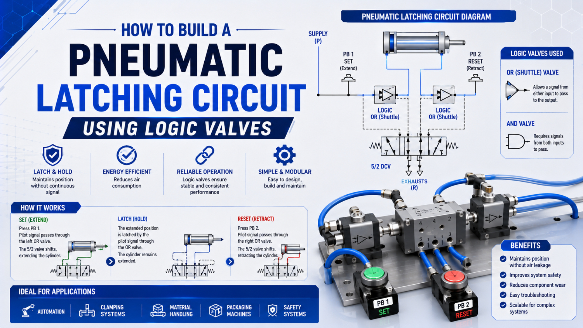
A pneumatic latching circuit uses a bistable memory element—commonly a double-air-piloted 5/2 directional valve—to retain its last commanded spool state after a momentary SET or RESET signal disappears. AND and OR valves can qualify those commands, but they do not create the memory by themselves.
Build the basic circuit by connecting separate momentary 3/2 signal valves to the two pilots of the bistable valve. Before commissioning, define what happens when neither signal is present, both signals arrive together, supply air is lost, or pressure returns. The retained control state must not be confused with guaranteed cylinder-position holding or a validated machinery safety function.
Key Takeaways
- The double-piloted valve or dedicated SET/RESET element stores the command state; AND and OR valves only process input conditions.
- Treat simultaneous SET and RESET as a prohibited state unless the circuit includes a documented priority function.
- Verify startup, air-loss, repressurization, leakage, exhaust, and restart behavior on the complete machine.
- An ordinary pneumatic latch is not an emergency stop, two-hand protective control, or load-holding safety device.
What Actually Stores the State in a Pneumatic Latching Circuit?
A pneumatic latch needs an element with two stable commanded states. A double-air-piloted 5/2 valve is a common implementation: a pulse at one pilot shifts the spool one way, and a pulse at the opposite pilot shifts it back. With neither pilot commanded, the spool remains in its most recently selected position under the conditions defined by the manufacturer.
SMC lists its VR4152 as a double-pilot relay valve, separately from its shuttle, AND, and two-hand-control products (SMC VR series, retrieved 2026). That separation captures the design boundary: the relay valve can provide bistable state, while the logic elements decide which pilot receives a signal.
Pneumatic memory is retained valve or logic state after the initiating signal has ended. It does not mean the circuit stores pressure indefinitely. Valve leakage, cylinder leakage, tube failure, or loss of supply can change downstream pressure even if the spool itself does not receive a new command.
The broader guide to pneumatic logic valves explains AND, OR, NOT, timing, and memory functions. This article stays narrower: it shows how to assign SET and RESET commands to one bistable output stage and how to prove every relevant state.
| Element | Role in the circuit | What it does not prove |
|---|---|---|
| Double-piloted 5/2 valve or SET/RESET memory valve | Retains the last commanded output state | Retained downstream pressure or actuator position |
| Momentary 3/2 SET valve | Produces the SET pilot pulse | Reset priority or safe startup |
| Momentary 3/2 RESET valve | Produces the RESET pilot pulse | Emergency-stop performance |
| AND valve | Requires two valid conditions before passing a command | Safety integrity or two-hand-control compliance |
| OR shuttle valve | Accepts either of two alternative command sources | Safe override behavior |
| Pressure regulator, tubing, fittings, and exhaust devices | Establish the pneumatic signal path | Adequate pilot pressure unless verified dynamically |
The most useful way to review a latching circuit is to ask where the state lives. If removing an AND or OR valve leaves the double-piloted valve in its last state, the memory lives in the output valve. If a dedicated memory module feeds a spring-return output valve, the state lives upstream. This distinction makes troubleshooting faster because it separates a failed decision signal from a failed memory element.
Which Components Do You Need for a Basic SET/RESET Latch?
Start with the selected double-pilot valve datasheet, not a generic port-number assumption. ISO 1219-1 defines rules for fluid-power graphical symbols, while ISO 1219-2 covers how those symbols are connected in circuit diagrams (ISO 1219-1; ISO 1219-2). The symbol printed on the selected component or manufacturer drawing remains the controlling reference for installation.
A practical bill of materials includes:
- One double-air-piloted 5/2 directional valve, or one dedicated SET/RESET memory element plus a suitable output valve.
- Two normally closed, momentary 3/2 signal valves for SET and RESET.
- A regulated and filtered signal-air supply within every component’s specified range.
- Tubing and fittings sized to deliver the required pilot pressure and pulse volume.
- Exhaust paths that allow each pilot line to return below the component’s FALSE threshold.
- Test points or gauges at both pilot inputs when commissioning access is limited.
- An actuator and speed-control arrangement selected independently for load, force, flow, and stopping requirements.
Do not select the logic valves from thread size alone. Check minimum pilot pressure, operating-pressure range, flow or conductance, internal leakage, response time, allowable back pressure, temperature, air quality, mounting orientation, and permitted pulse duration. These are product-specific values; a pressure threshold copied from another series is not a design rule.
For a modular installation, keep the memory valve, signal elements, and test points identifiable as one functional group. The modular pneumatic-circuit guide covers manifold boundaries, isolation, labeling, and fault-state documentation in more detail.
How Do You Pipe the Double-Piloted 5/2 Latching Circuit?
The basic connection is simple, but the labels must remain unambiguous:
- Connect regulated supply air to the 5/2 valve’s supply port.
- Connect its two working ports to the two chambers of the double-acting cylinder.
- Connect both exhaust ports to unrestricted, correctly sized exhaust paths.
- Feed the momentary SET valve output to one pilot, commonly identified as 14.
- Feed the momentary RESET valve output to the opposite pilot, commonly identified as 12.
- Label which cylinder motion each state commands; do not assume that “SET” must mean extend.
- Confirm that each 3/2 signal valve exhausts its pilot line when released.
Port identifiers vary with valve family and regional documentation. Verify P, A, B, exhaust, 12, and 14 against the selected manufacturer’s symbol before connecting tubing.
Bench-test the valve without a hazardous load before connecting it to the machine. Operate SET once, release it, and confirm the valve remains in the selected state. Operate RESET and repeat. If the valve changes state when a signal line vents, verify that the selected product is truly bistable rather than a single-pilot spring-return model.
What Should the SET/RESET Truth Table Specify?
A latching truth table needs a “previous state” column because the output cannot be determined from the current inputs alone.
| SET input | RESET input | Required next state | Engineering interpretation |
|---|---|---|---|
| 0 | 0 | Previous state | No new pilot command; memory retains the last selected state |
| 1 | 0 | SET | SET pilot must reach its valid pressure and pulse duration |
| 0 | 1 | RESET | RESET pilot must reach its valid pressure and pulse duration |
| 1 | 1 | Prohibited or explicitly prioritized | Do not assume which side wins |
The last row is the design trap. Two simultaneous pilot signals can produce model-dependent behavior influenced by pilot area, pressure, arrival time, spool friction, tubing volume, and internal construction. “Whichever arrives first” is not a safe or repeatable specification.
Choose one of these policies and show it on the schematic:
- Prohibit overlap: mechanical or logical interlocking prevents both commands from being present together.
- RESET priority: a purpose-designed priority arrangement suppresses SET whenever RESET is valid.
- SET priority: used only when the process requirement explicitly demands it and the resulting state is acceptable.
- External arbitration: a PLC or validated control subsystem generates mutually exclusive pneumatic commands.
Do not create priority by arbitrarily restricting one tube. A needle valve may change arrival time, but contamination, pressure, temperature, and tube replacement can change the race again.
A complete latch specification contains two tables: the command truth table above and a state-transition table covering startup, air loss, pressure return, manual override, and maintenance. The truth table describes intended logic; the transition table exposes hidden assumptions about stored energy and restart.
How Can AND and OR Valves Qualify the Latch Commands?
Add logic only when it expresses a documented control requirement. Each added element consumes pressure margin and adds leakage, volume, and response delay.
An AND valve is useful when SET should occur only after two ordinary process conditions are true—for example, “part present” AND “guarded automatic cycle enabled.” Feed the two conditions into the AND element and route its output to the SET pilot. This is a control interlock, not proof of a safety function.
An OR shuttle valve is useful when either of two ordinary command stations may request the same state. For example, “local reset” OR “remote reset” can feed the RESET pilot. Confirm that one source cannot backfeed the other and that both sources vent cleanly.
| Requirement | Logic arrangement | Important check |
|---|---|---|
| Either station may SET | OR element before SET pilot | One input must not pressurize the other input line |
| Two process conditions must be true to SET | AND element before SET pilot | The output must still meet the final pilot’s dynamic pressure requirement |
| Either fault signal should RESET | OR element before RESET pilot | Reset path must not be used as an unvalidated emergency-stop function |
| RESET must dominate SET | Purpose-designed priority or mutually exclusive controller outputs | Test both-input timing, stuck signals, and pressure loss |
Keep long cascades out of the pilot path. If several permissives, timers, and branches are needed, the pressure signal at the final valve may rise slowly or fail to vent completely. Measure it during switching rather than relying on the regulator gauge. For multi-step machinery, use the state-table method in the sequential cylinder circuit guide instead of adding undocumented latch branches.
What Must Happen at Startup, Air Loss, and Pressure Restoration?
ISO 4414 covers pneumatic-system design and significant hazards across installation, operation, maintenance, and reliable use (ISO 4414:2010, confirmed 2021). A latching circuit therefore needs defined behavior outside the normal SET/RESET sequence.
| Event | Question to answer | Acceptance evidence |
|---|---|---|
| Initial pressurization | Which spool state exists before the first valid command? | Controlled startup test from every possible prior state |
| Loss of signal air | Does the memory valve retain, drift, or change state? | Pilot and working-port pressures recorded during decay |
| Loss of main supply | Can the actuator move under load as pressure decays? | Guarded fault test plus load-restraint review |
| Pressure restoration | Can retained spool position cause immediate motion? | Repressurization test with outputs inhibited or sequenced |
| Both commands active | Which state has priority? | Recorded overlap test of the implemented arbitration method |
| Manual override used | Is the logical state now inconsistent with physical spool state? | Recovery procedure and state indication check |
| Blocked exhaust | Can residual pilot pressure prevent reset? | Dynamic pressure measurement at both pilot lines |
Never assume that a double-pilot valve powers up in a preferred state. Its last mechanical position may remain after shutdown, but maintenance, manual operation, vibration, pressure imbalance, or component replacement can change that state. If the machine requires a known startup condition, establish it with a controlled initialization sequence and confirm the resulting actuator position before enabling automatic motion.
Loss of supply is equally important. A retained spool connection does not preserve usable pressure indefinitely, and it does not restrain a vertical or externally loaded actuator. When air returns, the retained flow path can produce immediate motion. Use supply-enable logic, position feedback, guarding, and an independent load-restraint strategy appropriate to the risk.
How Do You Commission and Troubleshoot the Circuit?
Commission the signal layer before full-speed actuator operation:
- Compare the installed valve ordering code and symbol with the approved schematic.
- Verify supply, working, exhaust, and pilot ports with the manufacturer’s drawing.
- Disconnect or safely restrain the load and apply reduced, controlled energy where the component permits it.
- Measure the pressure at both pilot ports during SET, hold, RESET, and venting.
- Confirm that released 3/2 signal valves reduce their outputs below the memory valve’s FALSE threshold.
- Test the four SET/RESET input combinations, including the designed response to overlap.
- Cycle through supply loss and restoration from both latched states.
- Test manual overrides and define how the control state is reconciled afterward.
- Reconnect the actuator and verify direction, speed, end-position sensing, load behavior, and restart.
- Record the accepted pressure traces, state sequence, and machine response in the commissioning file.
| Symptom | Likely cause | Diagnostic check | Corrective direction |
|---|---|---|---|
| Valve will SET but not RESET | Insufficient RESET pilot pressure, blocked exhaust, crossed port, or stuck signal | Measure pressure at the RESET pilot while SET line is fully vented | Correct routing, exhaust restriction, pilot margin, or valve condition |
| State changes after releasing the button | Single-pilot spring-return valve installed, internal leakage, or incorrect model | Compare ordering code and symbol with the bill of materials | Install the specified bistable element or correct the circuit architecture |
| Valve chatters or shifts slowly | Marginal pilot pressure, long small-bore tube, leakage, or excessive logic stages | Capture dynamic pressure at the final pilot | Shorten or resize signal path and reduce unnecessary restrictions |
| Unexpected state after both buttons are pressed | No defined priority or timing-dependent race | Record both pilot pressures and arrival times | Add deliberate arbitration; do not tune the race with a flow restrictor |
| Cylinder moves when supply returns | Retained spool state reconnects pressure to a working port | Test repressurization from both latched states | Add a controlled supply-enable and verified startup sequence |
| Latch state is correct but cylinder drifts | Downstream leakage, air compressibility, or external load | Monitor chamber pressures and actual position | Treat position holding as a separate engineering problem |
Troubleshoot from the memory element outward. First determine whether the spool state is wrong or the actuator response is wrong. A correct spool state with a drifting cylinder points downstream; a wrong spool state with valid pilot pulses points to the memory valve; a missing pilot pulse points upstream into the logic chain.
Why Is This Latch Not an Emergency Stop or Two-Hand Safety Control?
ISO 13851 specifies requirements for two-hand control devices, including output dependency, prevention of defeat, fault avoidance, and verification based on risk assessment (ISO 13851:2019, confirmed 2024). Two ordinary manual 3/2 valves connected through an AND element do not by themselves demonstrate those properties.
ISO 13849-1 applies to safety-related parts of control systems across pneumatic, electrical, hydraulic, and mechanical technologies, but it does not assign a required performance level to a particular machine application (ISO 13849-1:2023). The risk assessment, safety-function specification, architecture, component data, diagnostics, common-cause measures, and validation determine whether the complete function is suitable.
Apply these boundaries:
- Do not route an emergency-stop command through an ordinary OR valve described as an “override.”
- Do not call a basic AND circuit a compliant two-hand control.
- Do not rely on the latch to hold a suspended or gravity-loaded actuator.
- Do not assume venting every circuit is always the safest response; pressure loss can release clamps or loads.
- Do not use retained pneumatic state as maintenance isolation. Stored pressure must be dissipated or restrained according to the machine’s energy-control procedure.
A mechanically latching cylinder is a different technology from a pneumatic logic latch. The latching-cylinder guide explains how a physical locking mechanism changes the load-holding boundary. For safety-related control architecture, use the separate ISO 13849 pneumatic safety-circuit guide.
Pneumatic Latching Circuit FAQs
Does a double-piloted valve keep its state after the SET signal is removed?
Yes, a correctly selected bistable valve is intended to retain the last commanded spool state after the momentary pilot signal vents. Confirm the behavior in the selected product’s datasheet and test it at the minimum expected pilot pressure. Retained spool state does not guarantee retained downstream pressure.
What happens if SET and RESET are pressurized at the same time?
Without an explicit priority arrangement, the result can depend on the valve design, pressure balance, arrival time, tubing, and spool friction. Treat simultaneous inputs as prohibited or implement and validate a defined SET- or RESET-priority function.
Will the latch hold a pneumatic cylinder in position after air loss?
No reliable position-holding claim follows from the latch alone. Air can escape through the valve, tubing, fittings, or cylinder seals, while external loads can move the actuator. Use a separately engineered rod lock, brake, stop, or other restraint when unintended motion creates a hazard.
Can a pneumatic latch be used as an emergency stop or two-hand control?
Not as an ordinary control circuit. Emergency-stop and two-hand protective functions require application-specific risk assessment, suitable architecture and components, fault handling, and validation under the applicable machinery-safety standards.
How should the circuit reset when compressed air returns?
Use a documented initialization sequence. Inhibit automatic motion, restore supply in a controlled manner, command the required startup state, confirm actual actuator position and permissive conditions, and only then enable the production sequence. Test that process from both possible retained spool states.
Sources and technical references
SMC: VR4151/VR4152 relay valve catalog, double-pilot relay valve classification and model identification. Retrieved 2026-07-22.
ISO: ISO 1219-1:2012 and ISO 1219-2:2012, fluid-power graphical symbols and circuit-diagram rules. Retrieved 2026-07-22.
ISO: ISO 4414:2010, general rules and safety requirements for pneumatic systems and components. Retrieved 2026-07-22.
ISO: ISO 13851:2019, two-hand-control design and selection requirements. Retrieved 2026-07-22.
ISO: ISO 13849-1:2023, methodology for safety-related parts of control systems, including pneumatic technology. Retrieved 2026-07-22.