

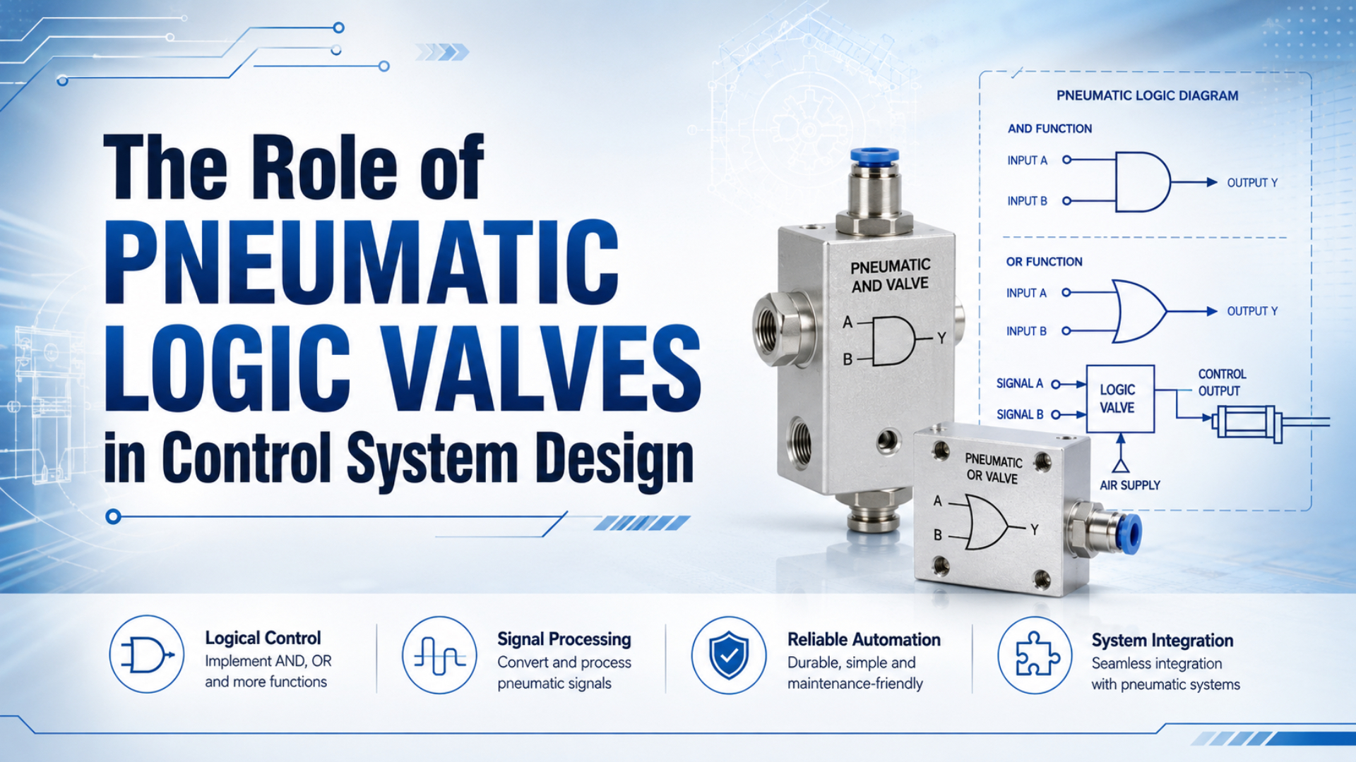
Pneumatic logic valves turn pressure signals into simple control decisions. An AND valve requires two valid inputs, an OR shuttle valve accepts either input, and timer or memory elements add sequence behavior. They work well for local interlocks and air-only functions, but component logic alone does not prove machine safety or hazardous-area suitability.
The practical design job is larger than drawing Boolean symbols. Each pressure state needs a defined threshold, every signal path needs enough flow, and loss of air must lead to a documented machine response. That places pneumatic logic inside the complete control-system review described by ISO 4414, not outside it.
Key Takeaways
- Festo lists 1 to 10 bar operating ranges for its training AND and OR valves.
- Truth tables define intended logic, while pressure, timing, leakage, and fault tests determine whether the circuit works.
- Ordinary logic valves are not automatically safety-rated, intrinsically safe, or suitable for explosive atmospheres.
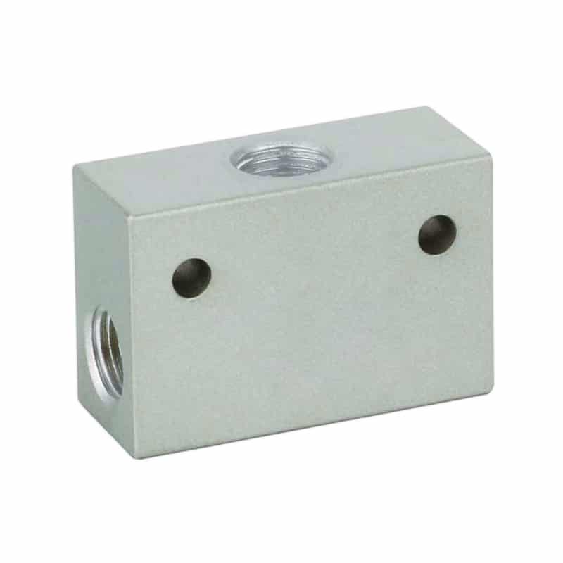
The ST Series pneumatic shuttle valve is a physical OR element: either inlet can pass a pressure signal to the outlet while the shuttle isolates the other inlet.
What Functions Do Pneumatic Logic Valves Implement?
Festo specifies a 1 to 10 bar pressure range for both its didactic AND and OR elements, with nominal flow ratings of 550 L/min and 500 L/min respectively (Festo Pneumatics and Hydraulics, 2026). Those values illustrate an essential rule: a logic function still has operating limits and flow capacity.
Pneumatic logic valve is a component that processes one or more air-pressure signals to produce a defined pneumatic output. A pressurized line is not automatically TRUE at every pressure. The circuit designer must define the minimum valid signal and the maximum permitted residual pressure for FALSE from the component datasheets.
The four common building blocks are:
| Function | Typical pneumatic element | Output rule | Design caution |
|---|---|---|---|
| AND | dual-pressure valve | output only when A and B are valid | unequal or late inputs can change output pressure and timing |
| OR | shuttle valve | output when A or B is valid | the higher or first-arriving input can dominate |
| NOT | normally open 3/2 element or pilot arrangement | output when the control input is absent | loss of signal and loss of supply are different events |
| MEMORY | bistable or set-reset element | retains a commanded valve state | retained spool state does not guarantee retained downstream pressure |
The basic truth tables are binary, but the installed circuit is analog underneath:
| A | B | AND output | OR output |
|---|---|---|---|
| 0 | 0 | 0 | 0 |
| 0 | 1 | 0 | 1 |
| 1 | 0 | 0 | 1 |
| 1 | 1 | 1 | 1 |
Festo also lists pneumatic timers adjustable from 2 to 30 seconds and a pneumatic counter with a 10 ms minimum drive pulse, 180 ms minimum reset pulse, and 2 Hz continuous counting frequency (Festo, 2026). Timing and pulse specifications are therefore component data, not universal properties of pneumatic logic.
How Do You Turn a Control Requirement Into a Pneumatic Circuit?
ISO 4414:2010, confirmed in 2021, covers pneumatic-system design, construction, installation, adjustment, operation, maintenance, reliability, energy efficiency, and significant hazards (ISO 4414, 2010). Start with machine states and fault responses, then choose logic elements that implement those requirements on the actual machine.
Truth table is a record of the required output for every binary input combination. Write it before drawing tubes. For example, “extend when either of two remote start valves is pressed” maps to OR logic. “Extend only when clamp pressure is proven and cycle enable is present” maps to AND logic, provided the complete function is suitable for the risk.
| Condition | Input A | Input B | Required output | What must be verified |
|---|---|---|---|---|
| idle | 0 | 0 | 0 | outlet vents below the FALSE threshold |
| command A only | 1 | 0 | application-specific | OR passes; AND remains off |
| command B only | 0 | 1 | application-specific | OR passes; AND remains off |
| both commands | 1 | 1 | 1 | outlet reaches pilot pressure within allowed time |
| one tube breaks | uncertain | uncertain | defined fault state | no unintended command or trapped hazard |
| supply disappears | 0 | 0 | defined mechanical state | load cannot move dangerously |
Treat the truth table as only the first layer. A useful control specification adds pressure thresholds, maximum response time, output flow, reset behavior, and every loss condition. Without those fields, two circuits can share the same Boolean table and still behave differently on the machine.
For a broader manifold and state-table workflow, see how to build a reliable pneumatic circuit with modular valves.
What Makes an Air-Signal Logic Circuit Reliable?
SMC lists 0.05 MPa minimum and 1.0 MPa maximum operating pressure for one current shuttle and AND-valve family, with a stated fluid and ambient range of -5°C to 60°C without freezing (SMC Shuttle Valve, retrieved 2026). Reliability begins by staying inside the selected component’s limits.
Pressure loss accumulates through pilot valves, logic elements, fittings, and long small-bore tubes. A downstream pilot may need a minimum pressure that the upstream TRUE signal cannot maintain during switching. Exhaust resistance causes the opposite fault: a supposed FALSE line stays pressurized long enough to delay reset or create an overlapping command.
Check these parameters for every signal chain:
- minimum and maximum operating pressure for each element;
- output flow or conductance, not just connection thread;
- pilot pressure required by the final directional valve;
- tube inside diameter, length, and volume;
- allowed input pulse width and output response time;
- leakage and residual-pressure limits;
- exhaust path, silencer condition, and contamination sensitivity;
- air-quality and temperature range.
One gauge at the regulator cannot reveal all of this. Add test points before and after a multi-element chain, then capture pressure during the command and reset. The compressed-air pressure-drop troubleshooting guide explains why dynamic readings are more useful than static pressure alone.
Cascading logic gates spends pressure margin. The first element may produce a valid signal on the bench, yet the final pilot may chatter or shift slowly after several restrictions. Design from the final pilot’s required pressure backward, and reserve margin for the lowest expected supply pressure and normal leakage.
Can Pneumatic Logic Valves Perform Safety Functions?
ISO 13849-1:2023 applies to safety-related control systems using electrical, hydraulic, pneumatic, and mechanical technologies, but it does not specify the safety function or required PLr for a particular machine (ISO 13849-1, 2023). A pneumatic AND gate alone is not evidence of an achieved safety level.
Two pressure inputs can express “A AND B,” but machinery safety also depends on architecture, component reliability, diagnostics, common-cause failures, fault reaction, reset behavior, validation, and the resulting hazardous motion. A standard dual-pressure valve should not be promoted as a two-hand safety-control device unless the complete function meets the applicable machinery standard and validated performance requirement.
Likewise, an OR valve is useful for alternative commands, but that does not make it an emergency-stop element. A stuck shuttle, crossed tube, residual pressure, or shared supply fault can defeat the intended response. Keep ordinary control logic separate from the safety-related function unless the risk assessment and validation deliberately include it.
For safety-related pressure removal, compare the logic design with safety exhaust valve integration. A logic output may request the function, but a rated output subsystem and tested machine response must perform it.
OSHA also identifies pneumatic energy as hazardous during servicing and maintenance (OSHA Control of Hazardous Energy, retrieved 2026). Control valves, interlocks, and pushbuttons do not replace the required isolation, stored-energy control, and verification under an applicable lockout/tagout procedure.
Are Pneumatic Logic Valves Intrinsically Safe in Explosive Atmospheres?
IEC 60079-11:2023 defines intrinsic safety “i” for electrical equipment and circuits incapable of causing ignition under the assessed conditions; the current edition incorporates corrections through May 2026 (IEC 60079-11). An air-only logic circuit should not borrow that electrical protection designation without the applicable conformity evidence.
Pneumatic equipment may reduce reliance on electrical signals in a hazardous zone, but non-electrical equipment can still present ignition risks through hot surfaces, mechanical sparks, static discharge, or material interactions. ISO 80079-36:2016 establishes methods and requirements for non-electrical Ex equipment with potential ignition sources (ISO 80079-36).
Before specifying pneumatic logic for an explosive atmosphere, document:
- zone or division, gas or dust group, and temperature classification;
- whether each valve, fitting, tube, silencer, actuator, and accessory is approved for that location;
- the conformity route for non-electrical equipment;
- electrical protection for any solenoid, sensor, transducer, or interface barrier;
- bonding, static-control, temperature, and material requirements;
- installation and maintenance conditions from the manufacturer.
“No coil at this valve” is not a complete hazardous-area assessment. It only removes one potential electrical component from the local function.
How Should Pneumatic Logic Interface With a PLC?
ISO 13849-1:2023 is technology-neutral across pneumatic and electrical subsystems, so a hybrid architecture must define the boundary and fault response of each interface (ISO, 2023). Use pneumatics where local pressure logic is useful and electronic control where diagnostics, sequencing, recipes, and communication justify it.
Common interfaces include pressure switches, pneumatic-to-electric converters, I/P or E/P converters, solenoid pilot valves, and monitored valve outputs. For pilot-stage behavior, read how pneumatic pilot-operated valves work.
Define each interface in both schematics:
| Interface field | Required record |
|---|---|
| signal meaning | what TRUE and FALSE mean physically |
| pressure or electrical thresholds | guaranteed switching and release values |
| normal state | output with commands removed |
| loss response | behavior after loss of air, power, communication, or pilot supply |
| timing | expected on-delay, off-delay, debounce, and timeout |
| diagnostics | how a mismatch or stuck state is detected |
| reset | manual, automatic, pressure-dependent, or sequence-dependent |
Avoid duplicate authority. If the PLC and pneumatic memory element can both latch the same command, the restart sequence may depend on which state returns first. Assign one owner for the state and use the other layer only as a documented interface or independent safety measure.
How Do You Commission and Troubleshoot Pneumatic Logic?
Festo’s current didactic data shows why timing must be measured: one pneumatic counter accepts a 10 ms minimum drive pulse but needs a 180 ms minimum reset pulse, an 18:1 difference (Festo, 2026). A circuit can pass a slow manual test and still miss production pulses.
Commission the circuit in a fixed sequence:
- Verify the schematic against the machine. Trace every port, tube number, normal valve position, and exhaust path.
- Test each input independently. Record its TRUE pressure, FALSE residual pressure, and transition time.
- Exercise the truth table. Apply every valid input combination, including the order in which simultaneous signals can arrive.
- Measure the last logic output. Confirm that it reaches the downstream pilot’s required pressure for the required duration.
- Test reset and exhaust. Look for retained pressure, blocked silencers, slow venting, and memory states.
- Inject documented faults safely. Remove one input, reduce supply pressure, interrupt pilot air, and simulate a broken or leaking signal line.
- Repeat at worst conditions. Use minimum permitted supply pressure, maximum expected cycle rate, and the real load state.
A useful fault table keeps troubleshooting focused:
| Symptom | Measure first | Likely causes |
|---|---|---|
| output never turns on | both element inputs | missing input, pressure below threshold, reversed porting |
| output chatters | final pilot pressure trace | marginal pressure, leakage, rapid input bounce |
| output will not reset | logic outlet and exhaust | trapped pressure, blocked exhaust, memory element state |
| OR command backfeeds | pressure at both inputs | wrong component, damaged shuttle, incorrect piping |
| production misses pulses | pulse width and response time | tube volume, slow pilot, timer or counter limits |
| fault appears only when actuators move | signal pressure during peak flow | shared supply pressure drop or undersized branch |
Do not clean a questionable logic valve internally unless the manufacturer provides a service procedure. Replacement, contamination correction, and a repeatable acceptance test are usually easier to validate than an undocumented internal repair.
Pneumatic Logic Valve Selection Checklist
Festo’s AND and OR examples differ by 50 L/min in nominal flow despite sharing the same 1 to 10 bar pressure range (Festo, 2026). Function names do not establish identical capacity, timing, materials, or interfaces, so procurement needs the complete operating envelope.
Include these fields in the specification or RFQ:
- required logic function and complete truth table;
- minimum TRUE and maximum FALSE pressure;
- supply-pressure range and lowest dynamic pressure;
- required output flow and downstream pilot demand;
- maximum on-delay, off-delay, and pulse-width requirements;
- allowed leakage and residual pressure;
- port type, tube size, mounting, and flow direction;
- air-quality, temperature, washdown, vibration, and material requirements;
- normal state, reset behavior, and response to air loss;
- hazardous-area or functional-safety requirements with applicable evidence;
- acceptance tests and documentation revision.
If the function drives a directional valve, include the valve’s pilot arrangement and minimum pilot pressure. If it participates in a safety function, send the safety requirements specification rather than asking the supplier for a generic “fail-safe” logic valve.
Frequently Asked Questions
Festo publishes different operating data for each logic element, including 1 to 10 bar ranges for its AND and OR valves and 2 to 30 seconds for two timer models (Festo, 2026). These answers explain the function; the selected datasheet sets the limits.
What is the difference between an AND valve and an OR valve?
An AND or dual-pressure valve needs valid pressure at both inputs before producing an output. An OR or shuttle valve passes either valid input to the outlet and isolates the other inlet. Festo’s examples both operate from 1 to 10 bar, but their nominal flow ratings differ by 50 L/min (Festo, 2026).
Does an OR shuttle valve add the pressure from both inputs?
No. It selects an available inlet path; it is not a pressure-adding device. When both inlets are pressurized, behavior depends on pressure balance, arrival order, and construction. SMC lists 0.05 MPa minimum and 1.0 MPa maximum operating pressure for one shuttle family, showing why manufacturer limits matter (SMC, retrieved 2026).
Can a pneumatic AND valve be used for two-hand control?
It can demonstrate the AND relationship, but a standard AND valve alone does not establish a compliant two-hand safety function. ISO 13849-1:2023 covers pneumatic safety-related control systems but does not prescribe the required function or PLr for a specific machine. Simultaneity, anti-tie-down, diagnostics, reset, architecture, and validation may all matter (ISO, 2023).
Will a pneumatic memory valve hold pressure after air supply is lost?
Not necessarily. A bistable element may retain its spool or logical state while downstream pressure decays through leakage or exhaust paths. ISO 4414 addresses significant pneumatic-system hazards across design and operation, so pressure retention, load risk, allowable decay, isolation, and mechanical response must be evaluated as system behavior (ISO 4414, 2010).
Do pneumatic logic circuits need electrical power?
Air-only logic elements can process pressure signals without local electrical power. The complete machine may still use electrically powered compressors, sensors, solenoids, PLCs, monitors, or safety controls. IEC 60079-11:2023 also limits intrinsic-safety “i” to assessed electrical equipment and circuits, so air-only control does not certify the whole installation (IEC).
Sources
- ISO 4414:2010, Pneumatic fluid power systems and components
- ISO 13849-1:2023, Safety-related parts of control systems
- ISO 80079-36:2016, Non-electrical equipment for explosive atmospheres
- IEC 60079-11:2023, Equipment protection by intrinsic safety “i”
- OSHA, Control of Hazardous Energy
- Festo, Pneumatics and Hydraulics learning components
- SMC, Shuttle and AND valve specifications
- Learnchannel-TV.com, Pneumatic logic valves