

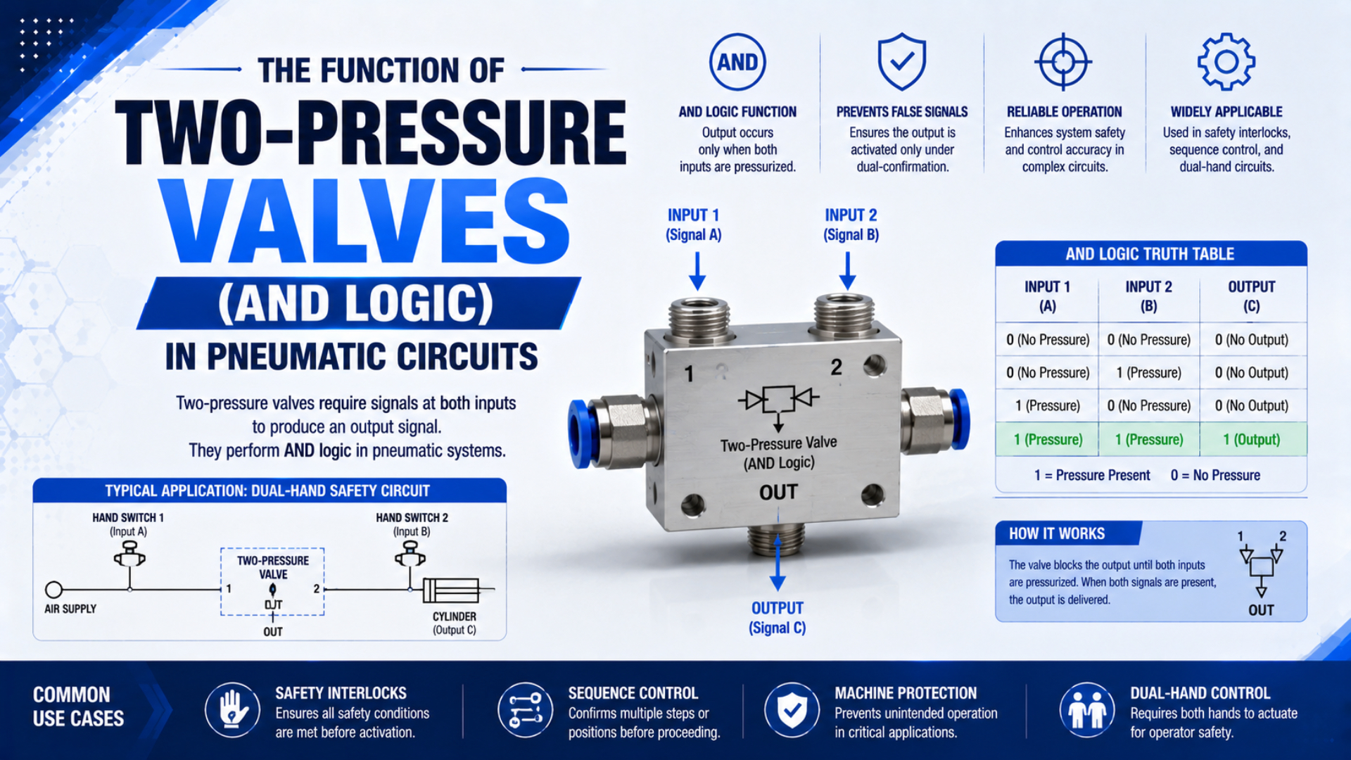
A two-pressure valve produces a pneumatic output only while both input signals are valid. That is the physical form of AND logic. The simple truth table is useful, but a working circuit also depends on input pressure, signal overlap, output flow, downstream pilot requirements, exhaust behavior, and the selected valve’s datasheet.
This distinction matters most when the two inputs represent machine permissions. An ordinary AND valve can combine those permissions, but it doesn’t automatically become a safety-rated two-hand control, emergency-stop device, or complete safety function. Those claims require a risk assessment, suitable components, defined fault behavior, and validation of the complete machine.
Key Takeaways
- A two-pressure valve has 4 binary input states, and only the A = 1, B = 1 state produces an output.
- With unequal inputs, some designs pass the lower pressure, so both signal paths must satisfy the downstream pilot requirement.
- Standard AND logic isn’t proof of a compliant two-hand safety function.
How Does a Two-Pressure Valve Produce AND Logic?
Festo’s didactic dual-pressure valve switches through when pressure is applied to both inputs; its published range is 1 to 10 bar with 550 L/min nominal flow for that model (Festo, 2026 catalog). Those figures describe one valve, not every AND element.
The valve has two input ports and one output port. Internal construction varies by manufacturer, so don’t assume that every product uses two pistons that add force against one spring. The stable functional description is simpler: one input alone cannot establish the specified output path, while two valid inputs can.
The Boolean relationship is , where and are valid pneumatic input states and is the resulting output state. In a real circuit, “valid” must include a pressure threshold. A weak signal can be logically present yet still fail to shift the downstream pilot valve.
| Input A | Input B | Output Y | Functional result |
|---|---|---|---|
| 0 | 0 | 0 | No output command |
| 0 | 1 | 0 | Input B alone is blocked |
| 1 | 0 | 0 | Input A alone is blocked |
| 1 | 1 | 1 | Output command is permitted |
The truth table describes permission, not machine motion. The output may only be a pilot signal for a larger directional valve. Cylinder speed, stopping distance, load behavior, and residual pressure belong to the downstream circuit and must be checked separately.
Unequal Input Pressure and Its Effect on Output
For Festo’s M5 AND gate, the lower of two unequal input pressures is fed to the output, while its listed AND-valve flow range spans 120 to 550 L/min across variants (Festo, 2024). Treat both behaviors as model-specific purchasing data for that product range.
Suppose input A reaches 6 bar while input B reaches only 3 bar. A compatible valve may produce an output near the weaker input, minus its internal losses. If the downstream directional valve needs more pilot pressure than the available output, the truth table says TRUE while the machine remains slow, unstable, or unresponsive.
Unequal pressure can come from several ordinary causes:
- different regulator settings;
- long or undersized signal tubes;
- restricted manual or mechanical input valves;
- clogged silencers or slow exhaust paths;
- leakage at fittings or seals;
- one signal feeding additional branches.
Measure both valve inputs and the output during the transition, not only at steady state. A static gauge reading can miss a short pressure dip that prevents the pilot stage from completing its stroke.
In our experience, troubleshooting is faster when technicians record all three pressures on one time base. Watching only the plant supply gauge can hide the restriction or leak on the weaker signal branch.
Do the Inputs Have to Arrive at Exactly the Same Time?
Festo describes its dual-pressure valve as switching when signals are applied to both inputs, but the published component sheet gives no universal millisecond simultaneity window (Festo, 2026 catalog). Ordinary AND logic therefore means overlapping valid signals, not automatically synchronized human actions for every application.
If input A arrives first and remains pressurized, the output stays off until B becomes valid. Once B arrives, the output can turn on. If A disappears before B arrives, no overlap exists and the output should remain off. How quickly it turns on or resets depends on valve construction, tube volume, restrictions, pressure, leakage, and the downstream pilot.
This is why a standard AND valve shouldn’t be sold as an anti-tie-down device. One input could be held continuously while the other is cycled. A safety-related two-hand function may need a defined time relationship, release requirements, prevention of defeat, diagnostics, and controlled reset. The logic symbol alone proves none of those properties.
For control design, write two separate requirements: the Boolean condition and the timing condition. “A AND B” defines which signals are needed. “A and B must become valid within the permitted interval and both must be released before restart” defines behavior that requires additional hardware or verified control logic.
How Should You Select a Two-Pressure Valve?
SMC specifies 0.05 to 1.0 MPa operating pressure and -5 to 60°C ambient and fluid temperature for its VR1211F AND valve, without freezing (SMC, current catalog). Those limits differ from Festo’s didactic model, so generic pressure rules are unreliable.
Start with the signal chain rather than the connection thread. The valve’s output often pilots another pneumatic element, and the pilot demand can be more important than the actuator’s main flow. If the AND valve is expected to feed a cylinder directly, confirm that the product is designed for that duty. Many compact logic elements are better treated as signal processors.
Use this selection checklist:
| Selection item | What to obtain | Why it matters |
|---|---|---|
| Operating-pressure range | Minimum and maximum for the exact part number | Both inputs must remain valid under worst-case conditions |
| Output characteristic | Output pressure with equal and unequal inputs | The weaker path may limit pilot pressure |
| Flow or conductance | Rated flow, Cv, Kv, or sonic conductance and test conditions | Determines how quickly downstream volume can pressurize |
| Downstream pilot demand | Minimum pilot pressure and required pilot flow | Confirms that TRUE can shift the next valve reliably |
| Reset behavior | Exhaust route, residual pressure, leakage, and release response | Determines how quickly FALSE is restored |
| Environment | Temperature, air quality, vibration, and mounting limits | Prevents operation outside the declared conditions |
| Documentation | Symbol, port numbers, service data, and conformity records | Supports installation, maintenance, and any safety review |
Don’t apply an arbitrary 25% flow margin or universal 40 psi threshold. Instead, compare the supplier’s worst-case output data with the downstream pilot requirement, then test the assembled circuit at minimum supply pressure, maximum expected restriction, and the least favorable temperature.
For broader logic-family selection, see the role of pneumatic logic valves in control-system design. That guide covers OR, NOT, memory, timing, and air-only architecture without turning this article into another general overview.
How Is an AND Valve Different from a Shuttle Valve?
Festo lists 550 L/min nominal flow for its didactic AND valve and 500 L/min for the companion OR shuttle valve, both over a stated 1 to 10 bar range (Festo, 2026 catalog). The numbers compare those models only; the decisive difference is logic.
| Input condition | Two-pressure valve, AND | Shuttle valve, OR |
|---|---|---|
| Neither input valid | Output off | Output off |
| A only valid | Output off | Output on from A |
| B only valid | Output off | Output on from B |
| A and B valid | Output on | Output on from the selected inlet path |
| Unequal valid pressures | Often governed by the lower input, verify datasheet | Often selects the higher-pressure path, verify datasheet |
Choose AND when the output requires two permissions. Choose OR when either of two command sources may provide the signal. A shuttle valve doesn’t add the two inlet pressures, and an AND valve doesn’t create redundancy merely because it has two inlets.
Could both appear in one machine? Yes. An OR valve may combine two permitted operating stations, while an AND valve combines the selected command with a process permission. Keep the state table explicit so alternate paths cannot bypass an intended condition.
Can a Two-Pressure Valve Perform a Safety Function?
ISO 13851:2019 defines 3 types of two-hand control device and covers output dependency, prevention of defeat, fault avoidance, selection, and verification (ISO, confirmed 2024). A standard two-pressure valve provides only the AND relationship unless its documentation establishes additional safety properties.
The standard also says it doesn’t determine which machines need two-hand control or which type a specific application requires. That choice follows the machine’s risk assessment and any applicable Type-C standard. A two-hand control protects the person using it; it doesn’t automatically protect other people near the hazard.
ISO 13849-1:2023 applies to safety-related control parts using pneumatic, hydraulic, electrical, and mechanical technologies, but it doesn’t prescribe the safety function or required performance level for a particular machine (ISO, 2023). The complete safety-related chain may include input devices, logic, output valves, diagnostics, pneumatic energy control, mechanical response, and reset behavior.
For the complete safeguarding question, use the dedicated guide to pneumatic two-hand controls. It covers anti-tie-down behavior, stopping response, safety distance, fault testing, and validation, while this article stays focused on the ordinary two-pressure valve itself.
An ordinary AND valve can still serve useful non-safety or risk-assessed control purposes, including:
- confirming clamp pressure before a process command;
- requiring a cycle-enable signal and an end-position signal;
- combining fixture-present and manual-command signals;
- permitting the next step in an air-only sequence.
For a safety-related pressure-removal function, review how safety exhaust valves integrate with machine guarding. An AND output may request a stop or vent action, but the selected output subsystem must perform and verify that action.
Commissioning and Troubleshooting the Circuit
Two binary inputs create 4 steady-state tests, and only 1 should produce an output. Festo’s two-input, one-output description provides the functional basis for this matrix (Festo, 2024). Commissioning should establish that baseline before adding delayed-input, unequal-pressure, leakage, blocked-exhaust, and restart tests.
Use pressure measurements at input A, input B, and output Y. If the valve pilots another valve, also record the downstream pilot pressure and the resulting valve position. Test at the least favorable supply condition allowed by the design, not just at a convenient shop setting.
- Apply no inputs. Confirm that output pressure falls below the defined FALSE threshold.
- Apply A only. Confirm that no valid output develops.
- Apply B only. Repeat the same check.
- Apply A and B. Confirm output pressure, rise time, and downstream pilot response.
- Delay B while holding A. Record whether output begins only after signal overlap.
- Remove A, then repeat by removing B. Check reset time and residual pressure.
- Reduce one input toward its minimum expected value. Confirm the downstream pilot remains stable or the circuit fails in the documented way.
- Restrict or block the intended exhaust path to verify that maintenance faults don’t leave a false signal trapped.
If one-input tests produce output pressure, check port identification, internal leakage, contamination, backfeeding from another branch, and incorrect use of a shuttle valve. If both inputs are valid but the output is weak, inspect regulators, tubing, fittings, input-valve restrictions, output loading, and the pilot requirement of the next valve.
When the AND output advances a sequence, compare the commissioning matrix with the state-table method for sequential cylinder circuits. A timer can detect a late transition, but it shouldn’t be treated as proof that an actuator reached its required physical position.
Record measured TRUE and FALSE pressure bands instead of writing only “works” or “fails.” That turns commissioning results into maintenance limits. A future technician can then distinguish a leaking logic element, a restricted signal path, and an undersupplied downstream pilot without guessing.
From our work reviewing pneumatic signal chains, the most useful service record is a compact table of input A, input B, output Y, downstream pilot pressure, and switching time under the same test condition. It makes later drift visible without inventing a universal pass value.
Two-Pressure Valve FAQs
ISO 13851 describes 3 two-hand control types, while ISO 13849-1 covers safety-related control design across pneumatic and other technologies. These scopes explain the central FAQ answer: an AND valve is a logic component, and its suitability depends on the complete circuit, machine risk, product data, and validation.
Does a two-pressure valve add the two input pressures?
No. A two-pressure valve isn’t a pressure booster or summing device. Festo states that its dual-pressure valve passes the lower pressure when the two inputs differ. Allow for internal loss and confirm the exact output characteristic in the selected product’s datasheet before comparing it with downstream pilot requirements.
Will the output disappear immediately if one input is lost?
The logical command should reset when either valid input disappears, but “immediately” isn’t a universal time value. Tube volume, outlet loading, restrictions, leakage, exhaust design, and the downstream pilot all affect pressure decay. Measure reset time and residual pressure in the assembled circuit under worst-case conditions.
Can a standard AND valve be used for two-hand control?
It can implement the basic A AND B relationship, but that alone doesn’t establish a compliant two-hand safety function. ISO 13851 also addresses device type, output dependency, prevention of defeat, fault behavior, selection, and verification. The required solution depends on machine risk assessment and applicable standards.
How should unequal input pressures be handled?
Trace the weaker signal path from its source to the valve, then compare the available output with the next valve’s minimum pilot requirement. Check regulator settings, tube size and length, fittings, leakage, branch loads, and input restrictions. Use the manufacturer’s unequal-pressure data instead of assuming both inputs average together.
Should the AND valve feed the cylinder directly?
Only if the manufacturer rates the exact valve for the required actuator flow and switching duty. Compact two-pressure valves are often used as signal elements that pilot a larger directional valve. Separating logic flow from actuator flow usually makes pressure, exhaust, replacement, and troubleshooting requirements easier to document.
Sources and technical references
- Festo, Pneumatics and Hydraulics: AND and OR valve operating data
- Festo, M5 Compact System: AND/OR gate functions and unequal-pressure behavior
- SMC, VR1211F Series AND Valve with One-touch Fittings
- ISO 13851:2019, Safety of machinery: Two-hand control devices
- ISO 13849-1:2023, Safety-related parts of control systems