

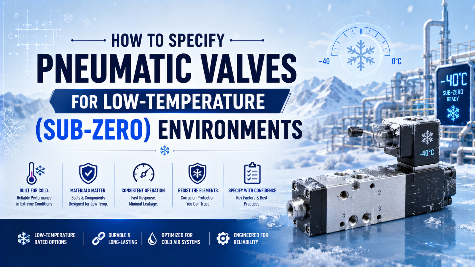
A low-temperature pneumatic valve is an exact ordered configuration. Its documented ambient, media, startup, pressure, flow, actuation, sealing, lubrication, and electrical limits must cover the installed duty. Specifying low-temperature pneumatic valves by body material, FKM seals, or a “sub-zero” label alone isn’t enough.
In this guide, sub-zero means below 0°C (32°F), but that is only a category. A purchasing specification must state the actual minimum temperature, where it occurs, how long the valve remains cold, and whether the first commanded cycle must work after a cold soak. Dry compressed air and rated hardware are separate requirements. You need both.
Key Takeaways
- Festo lists -40°C storage for one valve whose ambient operating limit is only -5°C.
- Actuation type can change a valve family’s minimum temperature by 30°C.
- Specify pressure dew point, pilot pressure, flow, seals, grease, coil, connector, and first-cycle acceptance separately.
What Temperature Limits Belong in a Valve Specification?
Festo lists -40°C storage, -5°C ambient operation, and -10°C media temperature for its MOCH valve (Festo, retrieved 2026). Those three numbers show why the lowest value on a datasheet cannot be quoted as the valve’s operating limit.
Start by defining four temperatures:
- Minimum ambient temperature: the air surrounding the valve, coil, connector, manifold, and enclosure.
- Minimum media temperature: the compressed air inside the valve, including local cooling during expansion and exhaust.
- Minimum cold-start temperature: the stabilized component temperature before the first required actuation.
- Storage and transport temperature: the allowable non-operating range, which does not prove that the valve can shift or seal there.
Record maximum temperature as well. A heated enclosure may protect a valve overnight but expose it to a higher local temperature when the heater, coil, and machine are operating together. The full cycle matters more than one winter minimum.
Published examples make the configuration differences visible:
| Exact published example | Ambient operation | Media temperature | Storage temperature | Specification lesson |
|---|---|---|---|---|
| Festo MOCH solenoid valve | -5°C to +40°C | -10°C to +60°C | -40°C to +100°C | Storage is not an operating rating |
| Parker Viking Xtreme, electrical actuation | -10°C to +50°C | Verify exact order code | Verify exact order code | Electrical actuation limits the cited family sooner |
| Parker Viking Xtreme, pneumatic actuation | -40°C to +60°C | Verify exact order code | Verify exact order code | Do not transfer this range to the solenoid version |
| AVENTICS R431002894 manual poppet valve | -40°C to +70°C | -40°C to +70°C | Verify supplier data | The named part, not NBR alone, owns the rating |
These rows are product examples, not a universal ranking. The valve function, actuation, pressure, flow, approvals, and application differ.
The usable temperature range is the intersection of every required limit, not the lowest number printed anywhere in the catalog. If the valve body is rated to -40°C but the coil connector, cable, pilot seal, or silencer is rated to -20°C, the installed assembly is a -20°C configuration unless those items are changed or controlled thermally.
How Does Valve Actuation Change the Low-Temperature Limit?
Parker lists -10°C to +50°C for electrically actuated Viking Xtreme valves and -40°C to +60°C for pneumatic versions in the same product family (Parker, retrieved 2026). A family name therefore does not establish one cold rating.
Direct-acting solenoid valves use magnetic force to move the main sealing element. They avoid a separate pneumatic pilot threshold, but coil force, spring force, seal friction, supply voltage, and orifice size still affect cold operation.
Internally piloted valves use supply pressure to move the main stage. They usually provide more flow for a given solenoid size, but they require the stated minimum pressure differential or pilot pressure. Cold-stiffened seals, a restricted pilot passage, or ice can turn a marginal pressure supply into a failure to shift.
Externally piloted valves separate pilot supply from the main process pressure. That can help when the main line starts at low pressure, but it adds another tube, source, seal path, and moisture-control point. Both circuits need a defined failure response.
Mechanical and pneumatically operated valves remove the solenoid coil from the configuration, not every cold-weather risk. Parker’s manual sliding-seal valve is one example rated from -40°C to +100°C, yet its documentation still requires moisture-free media when ambient temperature may fall below freezing (Parker, retrieved 2026).
Use the complete ordering code to confirm the actuator, return method, manual override, seal package, pilot arrangement, coil voltage, connector, and low-temperature option. Never transfer the rating from a pneumatic version to a solenoid version that only shares the same valve body.
When Does Compressed-Air Dryness Become a Valve Requirement?
ISO 8573-1 defines separate compressed-air purity classes for particles, water, and oil (ISO, 2010). For a valve exposed below 0°C, the water requirement must keep pressure dew point below the coldest internal air temperature, not merely below the compressor-room temperature.
Pressure dew point is the temperature at which water vapor begins to condense at the stated compressed-air pressure. If compressed air or an internal passage cools below that value, water can form. At a sub-zero location, the condensate can freeze in the pilot, spool clearance, exhaust, silencer, fitting, or drain.
A filter or FRL can collect liquid water and particles that reach its bowl, but it cannot reduce water vapor to a low pressure dew point. A refrigerated dryer also may not be enough for an exposed sub-zero branch. Follow the broader cold-weather pneumatic system guide for dryer, drain, piping, and winter commissioning design.
Parker offers desiccant systems with -20°C, -40°C, and -70°C pressure-dew-point options, but the cited dryer itself has a 5°C minimum operating temperature (Parker CDAS HL). That distinction is useful: a dryer can produce cold-rated air while still requiring installation in a warmer location.
Dry air and a low-temperature valve solve different failure mechanisms. Dry air prevents condensation and ice when the pressure dew point remains sufficiently low. It does not prevent seal stiffening, lubricant viscosity change, cable embrittlement, thermal contraction, weak pilot pressure, or low coil voltage.
State the required pressure dew point at a named pressure and sampling location. Measure it at the dryer outlet and at the critical point of use. The pressure dew point guide explains why an atmospheric dew-point reading cannot replace this requirement.
Which Seal, Lubricant, and Body Materials Should You Specify?
Parker lists approximate lower screening limits near -34°C for general nitrile, -54°C for low-temperature nitrile, and -26°C for general fluorocarbon (Parker O-Ring Handbook, 2021). These ranges show why FKM isn’t an automatic low-temperature upgrade for a dynamic valve design.
Material-family data can screen candidates, but it cannot approve a dynamic valve seal. Ask for the exact compound and valve configuration, then confirm pressure, media, leakage, friction, duty, surface, groove, and lubricant compatibility. A PTFE sealing element may still rely on an elastomer energizer whose cold behavior limits the assembly.
AVENTICS lists one H-Controlair poppet valve from -40°C to +70°C for both ambient and media, using NBR seals (AVENTICS R431002894). This does not prove that every NBR valve works at -40°C. It proves that the named configuration has a documented range.
The same caution applies to valve bodies. Stainless steel can help with corrosion and cleaning, aluminum can reduce mass, and brass can suit many ordinary valves. None of those material names establishes cold-start function. The exact alloy, casting or machining method, impact load, corrosion exposure, fasteners, coating, dimensions, and manufacturer qualification matter.
Specify lubricant as part of the valve, not as a winter maintenance guess. Obtain the factory grease option, approved service lubricant, compatibility statement, and relubrication instructions. Don’t increase airline lubrication or substitute a low-pour-point oil unless the valve manufacturer permits it.
For a deeper comparison of compounds and temperature effects, use the temperature and pneumatic seal selection guide. The polymer discussion transfers, but the final approval must still come from the exact valve supplier.
Flow, Pilot, Coil, and Connection Checks for Low-Temperature Pneumatic Valves
Parker’s cited Viking Xtreme range spans published flows from 1,140 to 4,680 L/min across sizes, while air-signal/spring versions list minimum operating pressures from 3.2 to 3.5 bar (Parker, retrieved 2026). Both values must match the exact circuit.
Size the valve from the required flow at the stated supply and downstream conditions. A port thread alone does not describe capacity. Obtain Cv, Kv, sonic conductance, critical pressure ratio, or a manufacturer flow curve, then account for fittings, tubing, manifolds, silencers, and exhaust paths.
For a piloted valve, document pressure at the pilot port while the machine is moving at maximum demand. Static plant pressure can look healthy while a remote branch drops below the shift threshold. Check pilot-tube length and inside diameter, restrictions, exhaust back pressure, residual pressure, and the reset threshold.
For a solenoid valve, specify:
- nominal voltage and allowed tolerance at the coil terminals;
- inrush and holding power where applicable;
- duty cycle and maximum coil temperature;
- minimum ambient temperature for the coil, connector, cable, and electronics;
- IP or NEMA protection required by snow, washdown, condensation, or dust;
- hazardous-area approval when the installation classification requires it;
- manual-override behavior and protection against unintended operation.
Festo publishes 12 ms on and 13 ms off switching times for its MOCH valve, together with the much warmer operating limits discussed earlier (Festo). Treat catalog switching time as a reference condition, not proof of the first-cycle response at the site’s cold-soak temperature.
Protecting the Installed Valve from Ice and Weather
Parker rates one manual sliding-seal valve from -40°C to +100°C and explicitly requires moisture-free media when ambient temperature may fall below freezing (Parker, retrieved 2026). Hardware rating and environmental protection remain separate design tasks for the installed valve station.
Place the valve where technicians can inspect it without entering a hazard zone. Protect it from snow, freezing rain, wash water, road spray, and condensate draining from higher piping. Keep exhaust flow from freezing onto walkways, sensors, guards, or adjacent valve stations.
Insulation slows heat transfer but does not create heat. A valve in an insulated box can still reach outdoor temperature after a long shutdown. If an enclosure heater or heat tracing is required, specify thermostat control, overtemperature protection, alarms, power-loss response, electrical classification, and the component manufacturer’s installation limits.
Avoid dead legs and water traps in pilot lines. Provide drains at actual low points, and make drain discharge lines resistant to freezing blockage. Verify tubing, fittings, cable jackets, connectors, silencers, pressure switches, and manifold seals at the same minimum temperature as the valve.
Contamination and ice can produce similar symptoms. If a cold valve shifts slowly, don’t assume moisture is the only cause. Inspect particle loading, lubricant condition, spool or poppet friction, pilot pressure, coil voltage, exhaust restriction, and downstream load. The control-valve contamination guide provides a separate fault-isolation workflow.
How Should a Valve Be Cold-Soak Qualified?
Festo’s MOCH catalog lists 12 ms energizing and 13 ms de-energizing under its published conditions, but its ambient operating minimum is -5°C (Festo). A project requiring -25°C must qualify an appropriate low-temperature model at -25°C rather than extrapolating that response time.
Cold-soak qualification is a controlled test of the complete installed valve configuration after specified locations have stabilized at the target temperature. The test should include the valve, manifold, coil, connector, pilot tubing, fittings, silencer, sensor, compressed-air condition, and representative downstream load.
Record a warm baseline first. Then cold-soak the assembly for the agreed dwell time and document actual component temperatures. Air temperature outside a chamber or enclosure does not prove that the valve body, grease, coil, manifold, and connected hardware have reached the target.
Measure the first required cycle after the longest expected idle:
- Ambient, valve-body, coil, and compressed-air temperature
- Pressure dew point and evidence that no liquid water is present
- Supply and pilot pressure during the switching event
- Coil-terminal voltage and current where relevant
- Energizing, de-energizing, and reset time
- External and internal leakage in every commanded state
- Main and exhaust flow, downstream response, and exhaust back pressure
- Repeatability over the required number of cycles and thermal transitions
Define acceptance limits from the machine requirement and supplier data. A valve that shifts only after several warming cycles has failed a first-cycle requirement. Do not average that failure away with later results.
In our experience, recording both the first cold cycle and the stabilized warm cycle exposes more than a pass/fail note. The comparison helps separate moisture, weak piloting, electrical voltage drop, seal friction, and exhaust restriction. Keep the measurement setup unchanged so future maintenance results remain comparable.
What Should the RFQ and Supplier Submittal Contain?
The AVENTICS example identifies separate -40°C ambient and media minima, a 0.1 to 14 bar pressure range, and 900 L/min nominal flow for one part number (AVENTICS R431002894). A useful RFQ asks every supplier for that level of configuration-specific evidence.
Send these requirements:
- exact minimum and maximum ambient temperatures;
- exact minimum and maximum compressed-air temperatures;
- cold-start temperature, dwell time, and required first-cycle behavior;
- valve function, porting, normal state, actuation, return, and manual override;
- supply, pilot, and exhaust pressure ranges, including dynamic minimums;
- required flow or conductance and the test standard or reference conditions;
- seal compound code, valve-seat or spool design, and leakage limit;
- factory grease or lubricant option and service instructions;
- coil voltage, tolerance, power, duty, connector, cable, and enclosure rating;
- pressure dew point plus particle, water, and oil limits at a named location;
- manifold, tubing, fittings, silencers, sensors, heaters, and drains;
- vibration, shock, corrosion, washdown, food, outdoor, or hazardous-area duty;
- cold-soak test method, instruments, acceptance limits, and required records;
- full ordering code, approved drawing, datasheet revision, and spare-parts list.
Ask the supplier to identify every requested option that changes the temperature range. A low-temperature seal kit may not be compatible with every solenoid, manual override, certification, manifold, or lubricant option.
This article specifies the valve. Use the separate sub-zero pneumatic cylinder guide for actuator seals, cushioning, sensing, mounting, and cold-start motion. Linking the two specifications is safer than assuming the valve and cylinder share one temperature rating.
Low-Temperature Pneumatic Valve FAQs
Festo publishes four different thermal boundaries for its MOCH valve: storage, ambient, media, and operating duty data (Festo). These FAQs apply the same configuration-first rule to temperature claims, seals, air drying, pilot pressure, cold-start testing, and retrofit decisions in demanding sub-zero installations.
Does a -40°C storage rating mean the valve can operate at -40°C?
No. Storage temperature applies while the component is not required to function. The allowable ambient, media, cold-start, coil, connector, seal, grease, pressure, and duty limits can be warmer. Festo’s MOCH example stores at -40°C but lists -5°C minimum ambient operation, showing why each boundary must be checked separately.
Is FKM or Viton always the best seal for a sub-zero valve?
No. Parker’s general screening data places ordinary fluorocarbon above some low-temperature nitrile compounds at the cold end. Dynamic valve performance also depends on exact formulation, seal profile, friction, grease, pressure, surface, leakage, and media. Select a manufacturer-qualified valve configuration, not a polymer name alone.
Does a low-temperature valve eliminate the need for a desiccant dryer?
No. A valve’s temperature rating covers its configured materials and function; it does not prevent water vapor from condensing and freezing. Set pressure dew point below the coldest internal temperature with a justified margin, then verify it at the critical point of use under the actual pressure and flow conditions.
Why can a pilot-operated valve fail even when plant pressure looks normal?
The pilot port may see a lower dynamic pressure because of long tubing, small fittings, restrictions, competing demand, ice, or exhaust back pressure. Compare measured pilot pressure during switching with the exact model’s minimum requirement. A static gauge near the compressor cannot prove that the remote pilot has enough pressure.
Can a standard valve be retrofitted with seals and a heater?
Only with written manufacturer approval and a validated installed test. New seals can conflict with grooves, grease, friction, leakage, coil force, certifications, and spare parts. A heater controls local temperature but does not dry the air, qualify accessories, or extend the valve beyond its approved configuration by itself.
Sources and technical references
- Festo: MOCH-3-1/8 Solenoid Valve Technical Data
- Parker: Viking Xtreme Pneumatic Valve Operating Data
- Parker: Manual and Mechanical Pneumatic Valve Catalog
- AVENTICS: H-Controlair R431002894 Product Data
- Parker: O-Ring Handbook ORD 5700
- ISO 8573-1:2010: Compressed-Air Contaminants and Purity Classes
- Parker: CDAS HL Heatless Compressed-Air Dryer System