

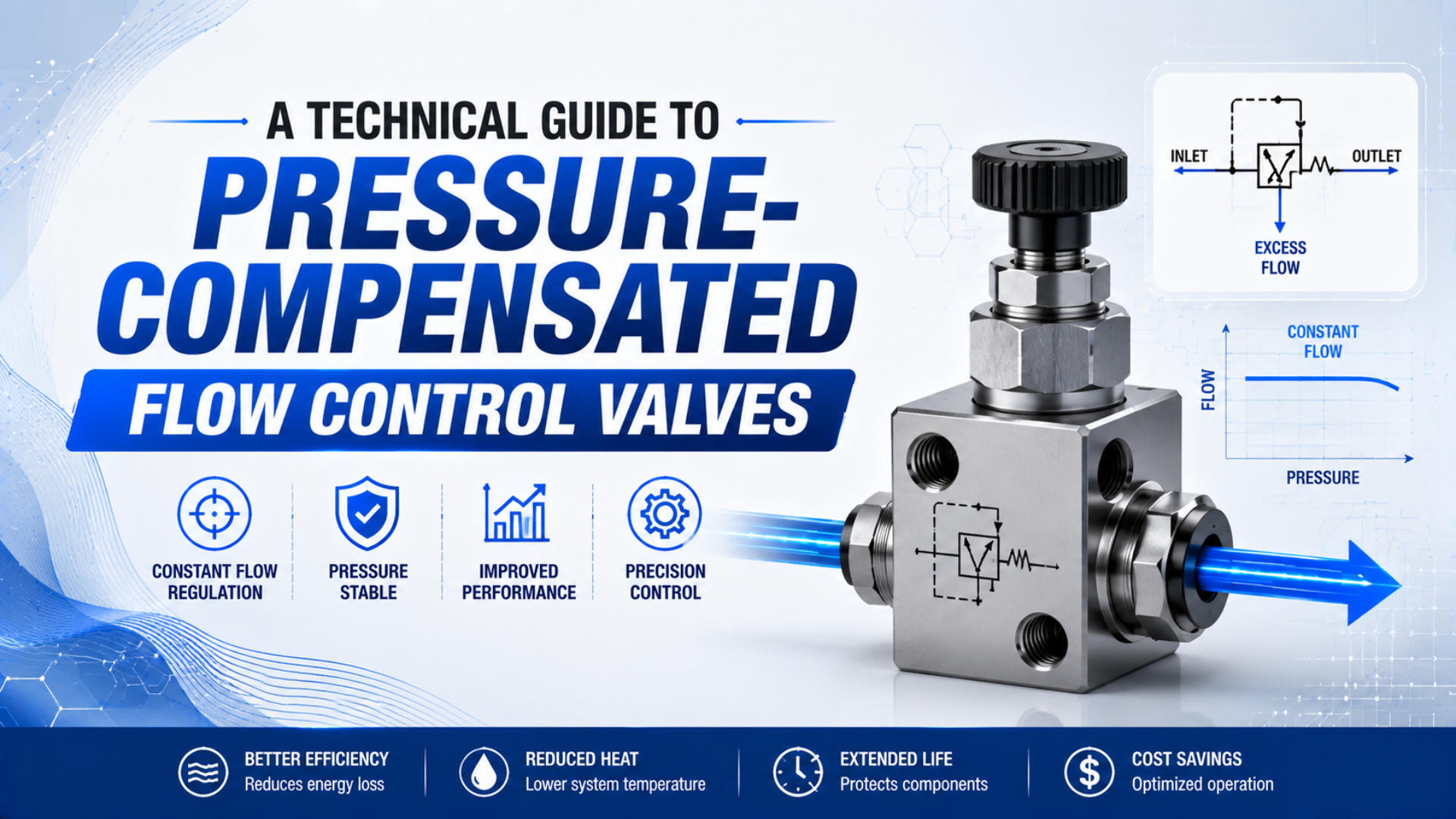
A pressure-compensated flow control valve is a device that adjusts an internal restriction so its set flow changes less when inlet pressure or downstream pressure changes. It does not hold flow constant under every condition. The valve must remain inside its specified pressure, differential-pressure, flow, temperature, and media limits. That distinction is especially important in pneumatics. Gas density changes with pressure and temperature, and a restricted passage can approach choked flow. A useful data sheet therefore states whether flow is actual volume, standard volume, or mass flow, together with the reference conditions. A Cv value alone cannot prove compensation performance.
Key Takeaway: Pressure compensation holds the pressure difference across a metering restriction near a design value, not under every condition. One commercial pneumatic-compatible model uses a factory-set 10 psi differential. Verify the valve’s flow tolerance, gas reference conditions, inlet and outlet limits, direction, and transient response before selection.
This guide focuses on identifying, selecting, and testing compensated pneumatic flow control. For a broader comparison of restrictors, check valves, and exhaust controls, start with the main pneumatic flow-control valve guide.
In this guide: what compensation controls, how the mechanism works, where compensation ends, device-class differences, selection, circuit direction, commissioning, and FAQs.
What Does Pressure Compensation Actually Control?
Festo distinguishes an ordinary throttle, whose flow depends on the pressure difference, from a pressure-compensated flow valve that maintains a set volumetric flow as pressure drop changes. The controlled variable is the differential across a metering element, not inlet pressure by itself (Festo Flow Control Valves).
In a passive compensated valve, the adjustment sets a metering area. A diaphragm or spool senses pressure on both sides of that restriction and moves a second variable opening. When available differential pressure rises, the compensator closes enough to keep the metering differential near its design value. When differential falls, it opens.
The familiar orifice relationship explains why this works conceptually:
Here, is flow, is the selected metering area, and is the pressure difference across that metering element. Holding approximately constant makes primarily a function of the setting .
This expression is a principle diagram, not a compressed-air sizing equation. Gas density, absolute pressure, temperature, discharge behavior, and choking affect pneumatic flow. ISO 6358-3 addresses steady-state flow characteristics for pneumatic component assemblies under subsonic and choked conditions, so final sizing must use the manufacturer’s gas-flow data and stated reference conditions (ISO 6358-3:2014).
The quickest catalog check is to look for a specified compensation differential or controlled pressure drop. Beswick’s PCFCD, for example, uses a factory-preset 10 psi differential across its adjustable orifice and lists a separate air-flow range. That is evidence of compensation. A product name containing “precision” or “speed controller” is not (Beswick PCFCD).
How Does the Compensator Hold Flow Near the Setpoint?
One commercial passive design uses a low-friction diaphragm with a factory-preset 10 psi control differential and a 135 psig maximum inlet rating at 70°F. Beswick also says this PCFCD is primarily intended for liquids. That qualification matters before using an apparently suitable valve with air (Beswick PCFCD).
Suppose downstream restriction increases while inlet pressure remains steady. The pressure available across the valve decreases. The compensator shifts toward a larger internal passage, leaving more of the available pressure drop across the fixed setting. If downstream pressure falls, the compensator throttles the variable passage to prevent the metering differential from rising proportionally. The mechanism cannot create pressure. If inlet pressure falls too close to outlet pressure, the variable passage eventually reaches its fully open position. From that point onward, flow falls with the remaining pressure differential. At the opposite extreme, pressure, temperature, spring force, friction, seal behavior, and passage capacity impose upper limits. A good performance statement therefore has four parts: set flow, inlet-pressure range, permitted outlet or backpressure range, and accuracy or flow-deviation band. If a catalog gives only maximum pressure and port size, it has not described compensation performance.
Where Does the Compensation Window End?
The Beswick example lists 135 psig maximum inlet pressure at 70°F, a preset 10 psi control differential, and a separate 0 to 20 standard cubic feet per hour air range. These are product data, not universal pneumatic-valve limits. This combination defines one usable envelope rather than an industry rule (Beswick PCFCD).
Expect compensation to weaken or disappear in these conditions:
- Insufficient differential. Once fully open, the compensator cannot protect flow.
- Flow outside the calibrated range. Very small openings become sensitive to contamination. At the other end, a fully open metering element may exceed the compensator’s authority and leave the setting without useful adjustment resolution.
- Excess backpressure. A restrictive silencer, undersized exhaust valve, shared manifold, or long tube can consume the available differential.
- Pressure or temperature beyond the rating. Spring behavior, diaphragm force, gas density, seals, and housing stress no longer match the published envelope.
- Fast transients. Passive mechanical elements need time and travel to respond. A short cylinder stroke may finish before the flow settles.
Do not use supply pressure alone to judge margin; measure immediately upstream of the flow valve and immediately downstream during motion. The available valve differential is . Static gauges, regulator settings, and compressor receiver pressure can all hide the local dynamic condition.
For more on the upstream causes of lost differential, see the guide to compressed-air pipe sizing and pressure drop.
Passive Compensation, Needle Valves, and Electronic Control
Festo’s electronic VPCF data sheet lists 0.5% full-scale repetition accuracy, 3% full-scale absolute accuracy, and 0.8% full-scale hysteresis for the documented variants. The device integrates sensors and control electronics, is non-reversible, and illustrates what closed-loop documentation looks like; those model-specific values do not apply to passive valves (Festo VPCF Data Sheet).
The three device classes solve different problems:
| Device | What changes internally | Main feedback | What the setting represents | Typical limitation |
|---|---|---|---|---|
| Needle or one-way speed controller | User-set restriction stays fixed | None | Opening or indexed knob position | Flow changes with differential pressure |
| Passive pressure-compensated valve | Compensator varies a second passage | Mechanical pressure balance | Calibrated or nominal flow | Works only inside its compensation window |
| Electronic flow controller | Proportional element moves under sensor control | Measured flow and electronics | Commanded flow value | Needs power, correct signal interface, and response time |
An electronic proportional valve is not automatically a flow controller; it may command spool position without measuring flow. The proportional-valve guide explains the difference between an open-loop proportional command and a closed-loop controlled variable.
How Should You Select a Valve for Compressed Air?
ISO 6358-1 defines steady-state test methods for compressible-flow components with fixed or variable flow paths, but its scope excludes components whose internal feedback makes the coefficients unstable, such as regulators. Ask which test method and product-specific curve support the compensated-valve data instead of assuming one coefficient covers every condition (ISO 6358-1:2013).
Start the specification with the controlled result. State required flow and allowable deviation at the machine’s minimum and maximum dynamic inlet pressure, then state the downstream pressure or backpressure range. For air-flow units, include the reference standard and temperature. “500 L/min” is incomplete if the buyer cannot tell whether it means standard, normal, free-air, or actual volumetric flow.
Then verify these attributes against the exact part number:
- Media and cleanliness: compressed-air compatibility, filtration requirement, lubrication policy, and moisture tolerance.
- Compensation envelope: minimum inlet pressure, maximum inlet pressure, permitted outlet pressure, minimum valve differential, and calibrated flow range.
- Performance definition: flow tolerance, hysteresis, repeatability, temperature effect, response behavior, and the test conditions behind each value.
- Pneumatic capacity: manufacturer gas-flow curve, sonic conductance or Cv where supplied, port size, tube size, and downstream restriction. The separate valve Cv guide explains capacity sizing, but capacity is not compensation accuracy.
- Circuit behavior: preferred direction, reverse-flow capacity, integral check valve, shutoff behavior, restart behavior, and whether bidirectional use is permitted.
- Mechanical integration: thread standard, seal material, mounting orientation, adjustment lock, tamper resistance, temperature rating, and service access.
Do not add an arbitrary percentage as a “safety factor.” Oversizing can push the operating point toward the low end of the adjustment range, where resolution may be poor. Keep required flow inside the manufacturer’s useful control band and preserve enough dynamic pressure differential at the worst simultaneous demand.
Meter-In, Meter-Out, and Reverse-Flow Behavior
SMC describes meter-out control as comparatively stable against load changes because exhaust-side pressure restrains the piston, while noting that meter-in behavior is more load-sensitive. Its AS-R and AS-Q products also show that energy and speed claims depend on a defined circuit and application, not the word “flow control” alone (SMC AS-R/AS-Q Technical Brief).
For conventional cylinder speed control, meter-out is often the starting arrangement because it maintains backpressure on the exhausting chamber. That backpressure matters. It reduces the differential available across a downstream compensated valve, and a silencer or valve exhaust passage can reduce it further, so check the compensation window during motion. Meter-in can suit resistive loads, air-saving circuits, or products explicitly designed for supply-side control. It is a poor default for an overrunning load because the actuator can move faster than the entering air controls it. Vertical axes and other gravity-assisted loads need a separately engineered load-holding and safety strategy.
Reverse flow is a product feature, not an assumption. Many ordinary pneumatic speed controllers combine a restricted direction with free reverse flow through a check valve, as shown in Parker’s standard flow-control catalog (Parker Pneumatic Flow Controls). A passive compensated device may instead be one-way, bidirectional with different curves, or damaged by reverse differential. Draw the intended arrow on the schematic and verify the data sheet.
The dedicated meter-in versus meter-out guide covers load behavior in more detail.
How Do You Commission a Pressure-Compensated Flow Valve?
Festo’s electronic VPCF publishes 0.5% full-scale repetition accuracy separately from its 3% full-scale absolute accuracy and 0.8% full-scale hysteresis. A passive valve may specify fewer fields, but the commissioning logic is the same: reproduce the stated boundary conditions and compare measured flow with the permitted band (Festo VPCF Data Sheet).
Install temporary pressure measurement points directly before and after the device, then put a suitable air-flow meter downstream at the location and orientation required by its manufacturer. Record the flow meter’s reference basis so later readings remain comparable.
Use this commissioning sequence:
- Confirm part, arrow, media, and filter.
- Establish the normal setting at a stable mid-range operating condition. Record , , flow, temperature, actuator cycle time, and adjustment position.
- Recreate the minimum dynamic inlet pressure with all expected simultaneous consumers operating. Do not substitute the no-flow regulator gauge reading.
- Recreate maximum expected backpressure, including the installed directional valve, tubing, fittings, silencer, and shared exhaust path.
- Test start, stop, restart, and both commanded directions. Watch for a transient overspeed or slow recovery that a steady flow number would miss.
- Repeat at the upper inlet-pressure condition and compare every result with the product’s published tolerance band.
- Lock the adjustment, mark the accepted position, and archive the pressures, flow reference, temperature, cycle result, instrument identification, and final setting with the machine documentation.
If cylinder speed still changes while measured flow through the valve remains inside tolerance, the valve may be doing its job. Motion has other variables. Check load force, seal friction, cushioning, chamber pressure, valve switching, exhaust restriction, and stick-slip. Flow repeatability and motion repeatability are related, but they are not the same controlled variable.
Pressure-Compensated Flow Control Valve FAQs
Festo states that pressure-compensated flow valves maintain set volumetric flow as pressure drop changes, while its electronic VPCF data sheet separately publishes accuracy, hysteresis, direction, and operating limits. Those details frame the answers below: compensation is a bounded performance claim, not a promise of identical motion in every pneumatic circuit (Festo Flow Control Valves).
Is an ordinary pneumatic speed controller pressure-compensated?
Usually not. A normal needle speed controller fixes an opening, so flow changes when the pressure differential changes. A true compensated valve uses pressure feedback to vary another internal passage and should publish a compensation range, controlled differential, flow tolerance, or performance curve. Confirm the exact data sheet instead of relying on terms such as precision or constant speed.
Does pressure compensation keep cylinder speed perfectly constant?
No. It reduces flow change only within the valve’s published operating window and tolerance. Cylinder speed can still change with load, friction, cushioning, chamber pressure, valve timing, exhaust restriction, temperature, or stick-slip. Verify both measured valve flow and actual cycle time under the machine’s minimum and maximum operating conditions.
Can the same valve control flow in both directions?
Only if the manufacturer permits it. Some valves compensate in one direction and allow free reverse flow through a check valve. Others are non-reversible or have different curves in each direction. Match the schematic arrow, reverse-pressure rating, and reverse-flow data to the extension and retraction circuit before installation.
Is Cv enough to select a pressure-compensated pneumatic valve?
No. Cv describes flow capacity under defined test conventions; it does not state how closely a valve holds its set flow as inlet pressure or backpressure changes. Selection also needs gas reference conditions, calibrated flow range, minimum differential, compensation accuracy, hysteresis, direction, temperature, and the manufacturer’s pneumatic performance curve.
Does a pressure-compensated valve save compressed-air energy?
Not inherently. Passive pressure compensation still uses throttling and consumes a pressure differential. It may prevent excess flow when supply pressure rises, but energy savings require measured reductions in air consumption, pressure, leakage, or cycle demand. Compare machine-level air use before and after the change rather than assuming savings from the valve type.