

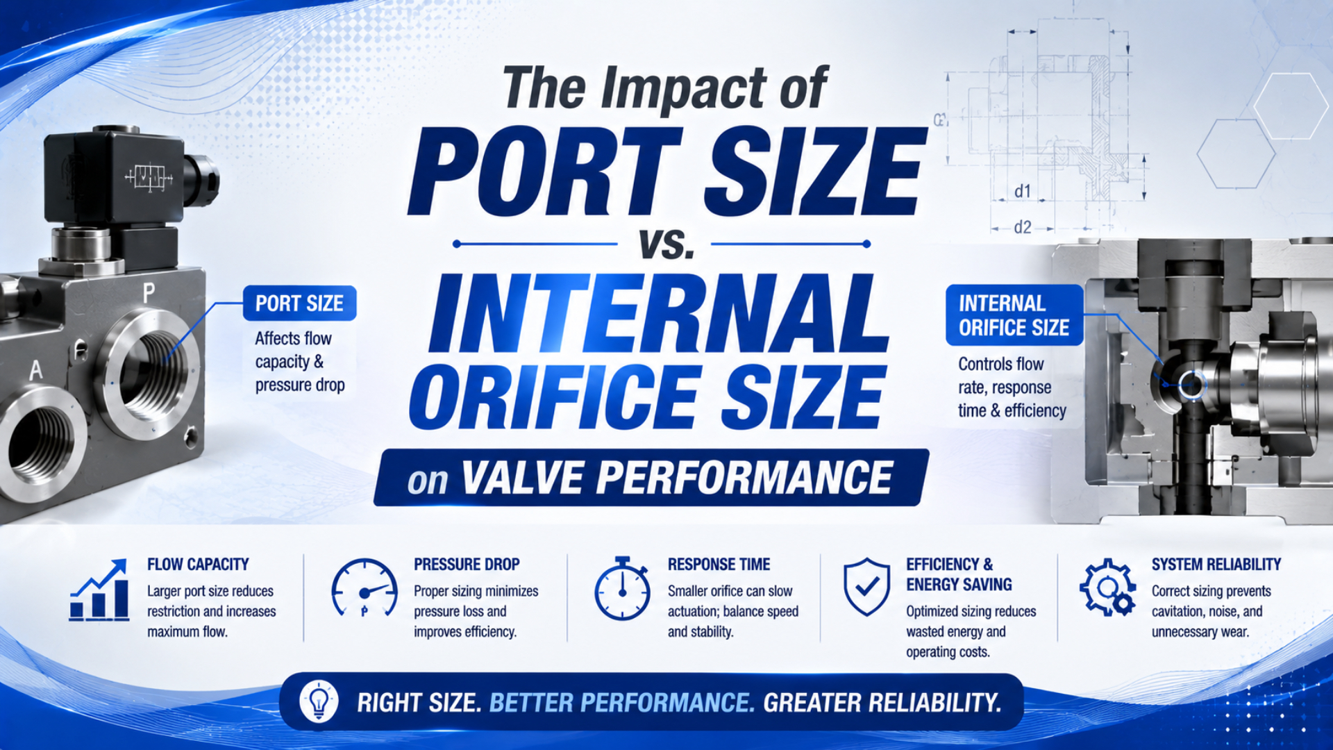
Port size defines how a pneumatic valve connects; it does not define how much air the assembled valve can pass. Actual capacity depends on the complete internal path, including galleries, spool or poppet openings, seats, seals, turns, manifold passages, and the exhaust route. Compare tested flow data before comparing thread labels.
This distinction matters during replacement work. A valve can bolt into the same manifold and accept the same fittings while producing a different pressure drop or cylinder time. The opposite is also possible: a larger port may add little flow because an internal passage remains the controlling restriction.
Key Takeaways
- SMC lists two 1/4-inch valves at Cv 0.9 and 1.7.
- Geometric area scales with diameter squared, but complete-valve flow does not.
- Use Cv or ISO 6358 data with stated pressure conditions.
- Verify the assembled supply and exhaust paths during motion.
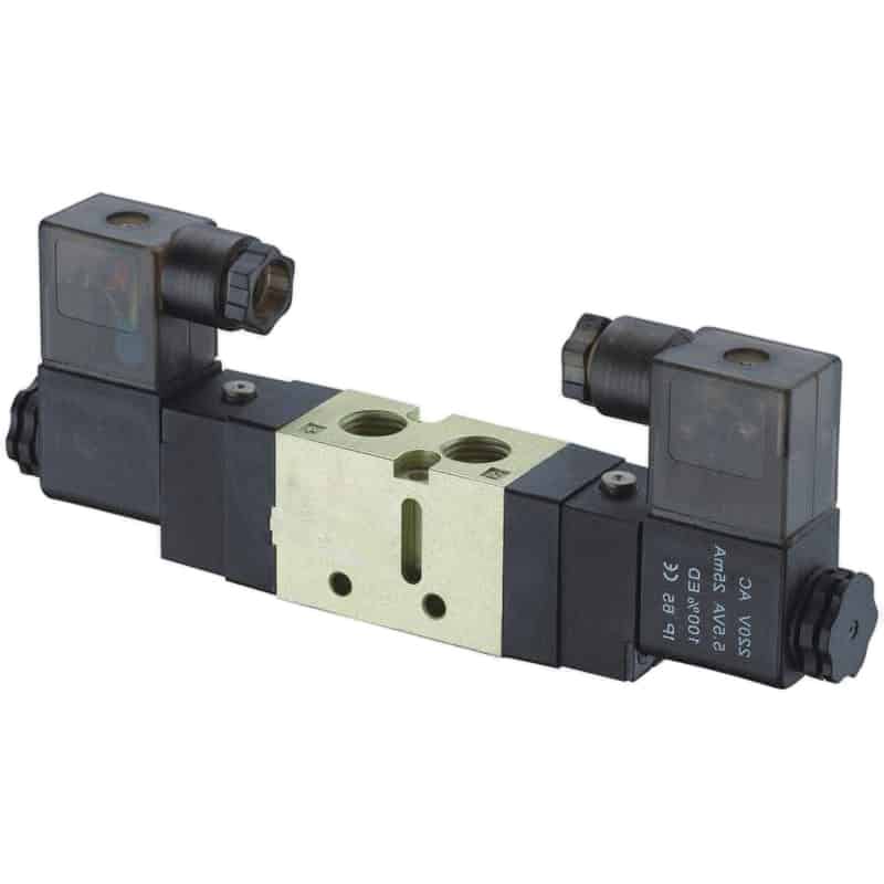
The VF and VZ directional solenoid valve family illustrates the visible part of selection: port count, thread, actuation, and mounting. Flow performance still comes from the exact configured valve data.
What’s the Difference Between Port Size and Internal Orifice Size?
SMC lists a VP344 valve with a 1/8-inch port at Cv 0.8 and the same model with a 1/4-inch port at Cv 0.9. The larger connection increases the published coefficient by only 0.1 in that configuration (SMC VP Series catalog, accessed 2026).
Port size is the specification for the mechanical or pneumatic interface. For a threaded valve, it may specify Rc, G, NPT, or another thread family and nominal size. For a push-in connection, it normally identifies compatible tube outside diameter. It answers: “What connects here?”
Internal orifice size is usually the diameter or area of an identified seat opening or bore inside the valve. The term is most useful when the manufacturer identifies one controlled opening, as many 2/2 fluid valves do. A multiway spool valve may not have one physical hole that represents the entire path. It can have several windows, turns, seals, and common galleries.
Effective flow capacity is the measured or derived performance of the complete configured path under stated test conditions. Cv, sonic conductance , critical pressure ratio , effective area, or a pressure-flow curve can express that performance. It answers: “What does this path pass at the stated pressures?”
These three descriptions belong on the same datasheet, but they are not interchangeable.
For valve-selection calculations that begin with cylinder demand, use the broader pneumatic flow-control valve sizing guide. This article stays focused on the evidence needed when the connection fits but the internal capacity remains uncertain.
Internal Geometry Forms a Series Flow Path
ISO 6358-3 calculates the steady-state characteristics of systems made from components and piping whose flow characteristics are known. That system-level method reflects an important physical fact: several restrictions in series determine the result, not one nominal port or one isolated diameter (ISO 6358-3, confirmed 2025).
Trace a 5/2 directional valve from supply to cylinder. Air may pass through the inlet fitting, a manifold gallery, a spool window, a body drilling, a cylinder-port fitting, and tubing. During exhaust, it follows a different path through another spool window and a silencer. The two directions may have different ratings.
A large inlet thread cannot compensate for a small spool opening. Likewise, a generous valve body cannot overcome a restrictive fitting, tube, flow control, or muffler. The hose and fitting size guide applies the same full-path principle between the valve and cylinder.
The term “internal orifice” can create false precision. For a multiway valve, ask which path and which state the quoted diameter represents. If the supplier cannot connect that dimension to a tested flow characteristic, treat it as geometry information, not a valve-capacity guarantee.
Why Doesn’t Geometric Area Guarantee Valve Flow?
ISO 6358-1 defines steady-state test methods for pneumatic components with fixed or variable internal paths. Its output characterizes the assembled component under compressible-flow conditions, which is more informative than calculating one circular area and assuming the result equals valve flow (ISO 6358-1, confirmed 2022).
For a circular opening, geometric area is:
Here, is cross-sectional area and is diameter. Use consistent units, such as square millimetres and millimetres.
The area ratio between two circular openings is:
If one ideal opening increases from 3 mm to 4 mm, its area ratio is about 1.78. That is a 78% geometric-area increase. It is not proof that the complete valve passes 78% more air.
Why not? Real flow also depends on the discharge behavior of the opening, upstream and downstream absolute pressure, gas temperature, contraction after the seat, spool position, surface geometry, and other restrictions. Once the pressure ratio reaches the component’s critical region, air can choke and no longer follow an incompressible square-root shortcut.
“Exponential” is also the wrong description. Area follows a power law with exponent two. Doubling diameter quadruples ideal circular area. It does not automatically quadruple the Cv, sonic conductance, or rated flow of an assembled valve.
For the gas-flow boundary, see the laminar versus turbulent valve-sizing analysis and the pneumatic pressure-drop calculation guide.
What Do Manufacturer Catalog Data Prove?
SMC publishes Cv 0.9 for a VP344 with a 1/4-inch port and Cv 1.7 for a VP544 with the same nominal 1/4-inch port. The second configured valve has about 89% more published Cv even though the connection label is unchanged (SMC VP Series catalog, accessed 2026).
The published catalog values isolate the article’s central point: connection compatibility does not establish internal capacity. Enlarging the VP344 connection from 1/8 inch to 1/4 inch changes Cv by 0.1, while retaining a 1/4-inch connection and moving from VP344 to VP544 changes Cv by 0.8.
| Model and configured port | Supply-to-output C | Critical ratio b | Cv | What the comparison shows |
|---|---|---|---|---|
| SMC VP344, 1/8 inch | 3.6 dm³/(s·bar) | 0.22 | 0.8 | Baseline configuration |
| SMC VP344, 1/4 inch | 3.9 dm³/(s·bar) | 0.22 | 0.9 | Larger port gives a modest gain in this body |
| SMC VP544, 1/4 inch | 7.5 dm³/(s·bar) | 0.16 | 1.7 | Same port, substantially different internal capacity |
SMC’s VQZ2000 catalog gives another warning. A metal-seal and rubber-seal version within the family have different published , , and Cv values for their supply and exhaust paths (SMC VQZ Series catalog, accessed 2026). Seal and spool construction can change capacity without changing the fitting interface.
Parker also publishes H Series values by valve size, port size, Cv, sonic conductance, critical ratio, nominal flow, and flow direction (Parker H Series catalog, accessed 2026). The catalog format itself is instructive: a port column is accompanied by several performance columns because no single connection dimension answers the sizing question.
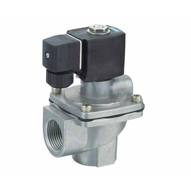
The VXF pilot-operated 2/2 valve family shows why valve architecture matters. A visibly large process port still needs a model-specific seat diameter, pilot requirement, pressure range, and flow rating.
Which Flow Rating Should Govern Selection?
ISO 6358-1 covers steady-state testing of pneumatic components, while its 2020 amendment adds effective conductance and its 2026 amendment addresses measurement uncertainty. These updates reinforce the same rule: compare data measured or derived under a defined pneumatic method, not an unlabeled “high-flow” claim (ISO 6358-1, 2013).
Use the value the manufacturer supports for the exact part number and flow direction:
| Published value | Best use | Required context |
|---|---|---|
| Cv | Compare valve capacity and use the supplier’s gas sizing method | Flow direction, inlet and outlet absolute pressure, gas, temperature |
| Sonic conductance C | Calculate or compare choked pneumatic capacity | ISO 6358 method and units |
| Critical pressure ratio b | Determine transition between subsonic and choked regions | Used with C and absolute pressure |
| Effective area | Compare components when the supplier states its test basis | Standard and pressure condition |
| Rated L/min or SCFM | Quick comparison within one catalog | Supply pressure, downstream pressure, and reference condition |
| Physical orifice diameter | Geometry and contamination-clearance review | Does not replace complete-path flow data |
Do not mix coefficients from unrelated conventions without checking the definition. Parker notes that its pneumatic valve Cv is calculated using a structured ANSI/NFPA test and warns that other calculation methods can produce different results (Parker Manual and Mechanical Valves, accessed 2026).
Treat the test method as part of the number. “Cv 1.0” without the component state, flow direction, and method is weaker evidence than a complete table containing , , Cv, and pressure conditions. The more complex the valve path, the less useful a bare orifice diameter becomes.
The Cv definition and valve-sizing guide explains coefficient terminology. When suppliers use mixed coefficient systems, use the Cv/Kv Converter for a first comparison, then return to the pneumatic flow curve.
How Should You Size a Valve Before Choosing the Port?
Parker’s published cylinder example calculates Cv 1.06 from cylinder area, stroke, supply-pressure compression factor, allowed pressure drop, and a one-second stroke time. The calculation begins with motion demand and finishes with a compatible connection, not the other way around (Parker Engineering Data, accessed 2026).
Use this sequence:
- Define the actuator bore, rod, stroke, load direction, and target extension and retraction time.
- Calculate peak flow during each moving stroke, not only cycle-average air consumption.
- Set the minimum usable pressure at the actuator while it moves.
- Allocate pressure loss across the FRL, directional valve, tubing, fittings, speed controls, cylinder ports, and exhaust.
- Select a valve capacity from Cv, ISO 6358 data, or a supplier flow curve.
- Choose the port and fitting configuration that can support that capacity.
- Check both supply and exhaust ratings for the selected spool state.
- Validate the result under the real load.
The calculator is a screening aid. A simple Cv relationship cannot represent every compressible-flow region, spool state, or manifold path. When the cylinder’s target time is the starting input, use the dedicated flow requirement workflow described in the complete valve-sizing article.
Never select the port first and assume the largest available body is automatically better. Oversizing can add cost, manifold space, switched volume, and larger fittings without improving the actual bottleneck.
How Do You Find the Dominant Restriction?
ISO 6358-3 provides a method for estimating overall steady-state characteristics from known component and piping data. In the field, the complementary test is dynamic: record pressure before and after suspected restrictions while the actuator moves, then compare the same loaded cycle (ISO 6358-3, 2014).
Use three pressure points:
- P1 at the valve inlet: exposes FRL, shared manifold, and supply-line loss.
- P2 at the active cylinder port: captures the valve supply path, fitting, and tube loss.
- P3 at the exhausting cylinder port or valve exhaust: exposes meter-out, return tubing, manifold, and silencer back pressure.
Record pressure and stroke time on the same time base. Test extension and retraction separately because they use different chamber areas and valve paths.
| Observation during motion | Likely interpretation |
|---|---|
| P1 falls in both directions | Upstream supply, FRL, shared manifold, or branch line is limiting |
| P1 is stable but P2 remains low | Valve path, supply fitting, tube, or speed control is restrictive |
| Driving pressure is adequate but P3 is high | Exhaust valve path, meter-out control, tube, or silencer is restrictive |
| A larger-port valve gives no measurable change | Another component or the actuator mechanics controls the result |
| One direction improves but the other does not | Supply and exhaust path ratings or spool windows differ |
Static pressure is not enough. A regulator gauge can show the expected value after motion stops while the cylinder still experiences a large transient drop. The complete pressure-drop troubleshooting guide covers shared supply and plant-side causes.
A substitution test needs two acceptance results: dynamic pressure at the actuator and loaded stroke time. Thread fit alone proves installation compatibility. Those measurements prove whether the replacement preserves the machine’s pneumatic performance.
Valve Replacement and RFQ Checklist
Parker’s H Series tables publish separate supply and exhaust characteristics, and SMC’s VP data distinguish both directions for each model. A replacement request that lists only “1/4-inch, 24 VDC, 5/2” omits the evidence needed to preserve flow performance (Parker H Series; SMC VP Series, accessed 2026).
Include these fields in the RFQ or substitution record:
- original and proposed full part numbers;
- valve function, normal state, number of positions, and return method;
- supply, cylinder, pilot, and exhaust port standards;
- configured fitting or manifold interface;
- minimum, normal, and maximum working pressure;
- flow requirement and allowed pressure drop in each active direction;
- Cv, and , effective area, or rated flow with test conditions;
- pilot pressure and pilot flow for pilot-operated designs;
- fluid, filtration, lubrication, and condensate conditions;
- ambient and air temperature range;
- seal and body material;
- voltage, power, connector, surge suppression, and duty;
- required response, leakage, endurance, and safety evidence;
- loaded extension and retraction acceptance times.
The spool-versus-poppet comparison helps explain why two valves with similar ports may have different leakage, response, pressure range, and internal capacity.
Do not machine a purchased valve to enlarge an internal passage. Changing a seat, spool window, or body drilling can invalidate pressure containment, sealing, pilot balance, response, material treatment, and the manufacturer’s rating. Select a documented larger-capacity model instead.
Port Size and Internal Orifice FAQs
SMC’s VP data provide the shortest answer to this topic: one 1/4-inch VP344 is rated at Cv 0.9, while a 1/4-inch VP544 is rated at Cv 1.7. The same connection can therefore support very different tested capacity, depending on internal valve design and configured path.
Can port size tell me the internal orifice diameter?
No. Port size identifies the connection, not every bore, gallery, seat, spool window, or exhaust passage inside the valve. Some 2/2 valves publish a specific seat diameter, but multiway valves often require path-level Cv or ISO 6358 data. Request the exact model drawing and flow table instead of estimating a universal ratio.
Does doubling the orifice diameter quadruple valve flow?
It quadruples the geometric area of one ideal circular opening. It does not guarantee four times the flow through an assembled pneumatic valve. Actual capacity also depends on discharge behavior, pressure ratio, spool position, turns, seals, other restrictions, gas temperature, and whether the flow is subsonic or choked.
Can a smaller-port valve outperform a larger-port valve?
Yes, when the smaller connection belongs to a valve with a more open internal path or higher tested conductance. Compare the exact Cv, sonic conductance, critical pressure ratio, or pressure-flow curve. Also check fittings and tubing, because a favorable valve rating can still be lost in the connected circuit.
Is Cv more useful than a published orifice diameter?
For complete-valve capacity, a properly defined flow coefficient or ISO 6358 data is normally more useful because it reflects assembled flow behavior. The value still needs its test method, gas, flow direction, and pressure conditions. Orifice diameter remains useful for geometry, contamination tolerance, and reviewing a clearly identified seat opening.
What should be measured after replacing a pneumatic valve?
Measure valve-inlet pressure, active cylinder-port pressure, exhaust back pressure where relevant, and loaded extension and retraction time. Use the same supply state, load, cushion settings, and flow-control positions before and after replacement. A matching thread confirms fit; dynamic pressure and timing confirm performance.
Sources and technical references
- ISO, ISO 6358-1:2013 Pneumatic Fluid Power, steady-state test methods for compressible-fluid pneumatic components. Retrieved 2026-07-22.
- ISO, ISO 6358-3:2014 Pneumatic Fluid Power, calculation of steady-state system flow characteristics. Retrieved 2026-07-22.
- SMC, VP300/500/700 Series Flow Rate Characteristics, configured port, , , and Cv values. Retrieved 2026-07-22.
- SMC, VQZ1000/2000/3000 Series, seal and flow-path characteristics. Retrieved 2026-07-22.
- Parker, H Series ISO Valves, port, Cv, sonic conductance, critical ratio, nominal flow, and directional data. Retrieved 2026-07-22.
- Parker, Pneumatic Valve Products Engineering Data, pneumatic Cv sizing example. Retrieved 2026-07-22.
- Parker, Manual and Mechanical Valves, pneumatic Cv test-method discussion. Retrieved 2026-07-22.
- AutomationDirect, Understanding Pneumatic Valve Ports and Ways, pneumatic port and flow-path context. Retrieved 2026-07-22.