

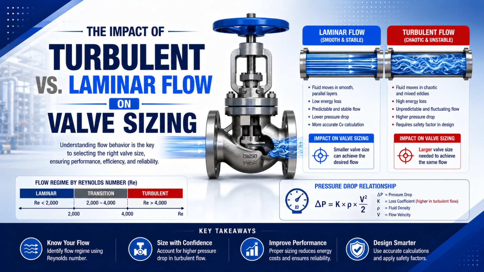
Turbulent versus laminar flow can affect a valve-sizing calculation, but Reynolds number is usually a correction check, not the primary size selector for a pneumatic valve. First establish the actuator’s flow demand and the dynamic upstream and downstream absolute pressures. Then use the manufacturer’s compressed-air curve, Cv method, or preferably ISO 6358 conductance data. Apply a low-Reynolds-number correction only when the chosen method requires one.
Key Takeaways
- MIT and Purdue place round-pipe transition between roughly 2,300 and 4,000; those thresholds do not describe every valve passage.
- Turbulence alone does not justify a larger pneumatic valve.
- ISO 6358 uses sonic conductance and critical pressure ratio to characterize compressed-air flow.
- Apply low-Re corrections only when the selected method or manufacturer requires one.
What Does Reynolds Number Actually Tell You?
Reynolds number is a dimensionless ratio comparing inertial effects with viscous effects in a defined flow passage. NASA gives the relationship using density, velocity, a characteristic length, and dynamic viscosity; it also notes that the characteristic length depends on geometry (NASA Glenn, Boundary Layer, accessed 2026).
For internal flow, a useful form is:
where:
- is local fluid density;
- is mean velocity in the passage;
- is hydraulic diameter, or another justified characteristic length; and
- is dynamic viscosity.
NASA’s Reynolds-number definition above supplies the formula; hydraulic diameter extends the pipe-diameter concept to non-circular internal passages. Because compressed-air density changes with absolute pressure and temperature, the Reynolds number at a valve inlet need not equal the value at its throat or exhaust. Re answers a regime question for a specified location. It does not directly answer the purchasing question, “Which valve size will deliver the required cylinder stroke time?” To answer that, the engineer still needs flow demand, pressure conditions, valve path, and manufacturer flow characteristics.
Use this order: demand, conductance, then Reynolds correction. Reversing it can produce a mathematically tidy answer for a passage that is not the controlling restriction.
Where Do the 2,300 and 4,000 Thresholds Apply?
MIT teaching material places round-pipe transition near and fully turbulent behavior near , while Purdue uses below 2,300, 2,300-4,000, and above 4,000 as practical pipe-flow bands (MIT OpenCourseWare, accessed 2026; Purdue University, accessed 2026).
Those numbers are useful, but their scope matters:
| Flow situation | What the familiar thresholds can tell you | What they cannot tell you |
|---|---|---|
| Long, straight, circular tube | likely laminar, transitional, or turbulent pipe flow | total machine pressure loss without length, roughness, and fittings |
| Short valve restriction | local inertial-to-viscous balance if geometry and local properties are known | valve capacity from port thread or nominal diameter alone |
| Spool with turns and area changes | whether a validated model may need a low-Re correction | one universal transition point for every internal passage |
| Exhaust jet or orifice | a local Reynolds estimate | whether the gas is subsonic or choked |
In fully developed laminar flow through a straight circular pipe, Purdue gives the Darcy friction factor as:
That relation is source-backed by Purdue’s pipe-flow notes and is restricted to that geometry and regime. Its scope is narrow. Likewise, the 2,300-4,000 band is not an operating range that machinery must always avoid. It marks uncertainty in a classical pipe-flow model, not an automatic reliability failure. Use the air velocity calculator to screen velocity in a known tube ID. Treat the result as one input to a tube-flow review, not as a substitute for valve conductance data.
Why Does a Pneumatic Valve Not Behave Like a Long Pipe?
Inside a valve are entrances, contractions, gaps, turns, seals, spool lands, outlets, and sometimes several unequal flow paths. ISO 6358-1 therefore specifies steady-state tests for pneumatic components with fixed or variable internal flow paths rather than asking users to reconstruct every passage from pipe equations (ISO 6358-1:2013, accessed 2026).
Geometry changes the model. Hagen-Poiseuille flow describes fully developed laminar motion in a long circular tube under restrictive assumptions. Darcy-Weisbach is excellent for distributed pipe friction when its friction factor and geometry are valid. A directional valve, however, often concentrates much of its loss around short restrictions and changing areas. Even valves with the same thread can have different effective openings and different supply-to-work-port versus work-port-to-exhaust capacities. Consequently, port size is a connection attribute; tested flow data describe performance. The companion pneumatic flow-control valve sizing guide covers the demand calculation and complete-path check in detail.
When Does Low-Reynolds-Number Flow Change Valve Sizing?
Emerson’s control-valve handbook says its standard sizing equations assume fully turbulent flow and requires additional treatment for high-viscosity or very low-flow service (Emerson, Control Valve Handbook, accessed 2026). The trigger is departure from the equation’s validated regime, not simply a preference for “smooth” flow.
Consider a low-Re correction when one or more of these conditions apply:
- flow passes through a capillary or micro-orifice;
- the gas is unusually viscous or the temperature materially changes its properties;
- flow demand is extremely low relative to the selected valve’s rated range;
- a proportional valve must regulate near the bottom of its usable command range, where deadband and minimum controllable flow also need verification; or
- the manufacturer explicitly publishes a Reynolds correction or minimum controllable flow.
Never use a universal oversizing allowance. Use the correction procedure supplied with the valve equation or selection software. If no validated method is available, request a flow curve or test point at the actual gas, pressure, temperature, and target flow. Slow cylinder motion does not prove low-Reynolds-number flow in ordinary factory air. A meter-out restriction can create a high local velocity even while carriage speed is low. Conversely, a large line can have modest mean velocity yet still feed a small, controlling valve throat.
Are Turbulence, Subsonic Flow, and Choked Flow the Same Thing?
No. Reynolds number describes the balance between inertial and viscous effects; choking describes a compressible-flow limit at a restriction. NASA shows that mass flow reaches a maximum when the Mach number at the controlling section reaches one (NASA Glenn, Mass Flow Choking, accessed 2026).
For pneumatic component data, critical pressure ratio is the downstream-to-upstream pressure ratio below which flow is choked. Sonic conductance is the parameter expressing choked-flow capacity. SMC denotes them as and respectively (SMC, Flow Characteristics of Pneumatic Components, accessed 2026). The diagnostic ratio is:
Here, and are upstream and downstream pressures measured during the same flow event. Both must be absolute. This formula follows the pressure-ratio definition in SMC’s ISO 6358 guidance. If falls below the component’s published , the tested path is in its choked region. Reducing downstream pressure further will not raise mass flow in the same way it did in subsonic operation.
| Question | Main parameter | Engineering decision |
|---|---|---|
| Are viscous or inertial effects dominant here? | Reynolds number | choose or correct the local loss model |
| Is the component in subsonic or choked flow? | versus | use the correct ISO 6358 flow relation or curve |
| Will the actuator meet its motion target? | required flow plus complete-path capacity | select and verify the valve, tubing, fittings, and exhaust |
Turbulent flow can be subsonic, and a restriction can choke without the pipe-style 2,300/4,000 labels answering the sizing question. For the full conductance method, read how sonic conductance and critical pressure ratio affect choked flow. The air-orifice flow calculator can provide a first-pass restriction check. Tested valve data remain the final reference.
Does Turbulent Flow Automatically Require a Larger Valve?
It does not. A larger valve is justified when the selected path cannot pass the required mass flow within the available pressure-drop budget. ISO 6358-3 explicitly addresses both subsonic and choked flow for systems made of components and piping, reinforcing that pressure conditions and tested system characteristics matter (ISO 6358-3:2014, confirmed 2025).
The statement “doubling flow quadruples pressure drop” is only a conditional approximation. In a fixed-density turbulent pipe model with a roughly constant friction factor, pressure loss scales approximately with the square of mean velocity. Across a compressed-air valve, density, expansion, discharge behavior, and the active internal path can all change as pressure ratio changes. Oversizing can also create control problems. A large proportional valve may use only a small fraction of its command range. An oversized directional valve may add volume and cost without fixing a long, narrow tube or clogged exhaust silencer. A small valve is equally problematic when dynamic inlet pressure collapses or the exhaust path limits cylinder speed.
In our experience reviewing pneumatic applications, we found that separating the symptom from the assumed cause prevents unnecessary valve changes. A slow cylinder can come from insufficient valve conductance, regulator droop, small tube ID, a restrictive fitting, meter-out adjustment, exhaust back pressure, load friction, or poor cushioning. Calling all of those “turbulence” hides the measurement that would distinguish them.
The practical selection criterion is performance at the worst credible operating point, not a preferred flow label.
A Safer Pneumatic Valve-Sizing Workflow
ISO 6358-1 covers component testing, and ISO 6358-3 extends the method to assemblies of components and piping. Together, they support a workflow based on demand, absolute pressure, temperature, and tested flow characteristics rather than an unsupported turbulence safety factor (ISO 6358-1; ISO 6358-3, accessed 2026).
- Define the motion or process demand. Record cylinder bore, rod diameter, stroke, load, target stroke time, cycle overlap, and required end pressure. For a blow-off or process stream, specify normal and peak mass or standard-volume flow.
- Map the real path. Record every supply and exhaust restriction, then check extend and retract separately.
- Use dynamic absolute pressures. Measure or estimate and while the demanding motion occurs. Static regulator pressure is not a substitute. Add local atmospheric pressure when converting gauge readings.
- Select with one consistent pneumatic method. Prefer the manufacturer’s ISO 6358 and data or a compressed-gas flow curve. If the catalog uses Cv, follow that manufacturer’s gas-sizing equation and stated limits.
- Check the model’s regime. Apply a low-Re correction only if velocity, characteristic size, gas properties, and the chosen method put the service outside the fully turbulent assumption. Check choking separately with pressure ratio.
- Verify the entire path. Confirm dynamic inlet pressure, actuator-port pressure, exhaust back pressure, flow, and actual stroke time. Repeat at minimum supply pressure and maximum simultaneous demand.
A valve is not “correctly sized” merely because its catalog flow exceeds a spreadsheet target. It is correctly sized when the installed supply and exhaust paths deliver the required motion, force, and repeatability at the worst operating condition without pushing the control element outside its useful range.
For upstream demand and restriction diagnosis, use how to calculate pneumatic flow rate together with the pneumatic valve pressure-drop measurement guide.
How Do You Verify the Selection on the Machine?
A bench flow rating describes controlled test conditions, while an installed valve shares pressure with real tubing, fittings, regulators, manifolds, and exhaust hardware; ISO 6358-3 therefore addresses flow-rate characteristics of component assemblies and piping, including subsonic and choked operation (ISO 6358-3, confirmed 2025).
Instrument the cycle that actually fails. Log valve-inlet pressure, active actuator-port pressure, the opposite chamber or exhaust pressure where practical, and stroke time on the same time base. A static gauge observed before the solenoid energizes cannot show regulator droop or transient line loss.
| Observation during motion | More likely interpretation | Next check |
|---|---|---|
| Valve inlet pressure sags | upstream path or regulator cannot support peak demand | regulator curve, filter, manifold, tube ID, simultaneous users |
| Inlet stays firm but actuator-port pressure is low | valve or downstream supply restriction | path-specific , , Cv, fittings, speed controller |
| Supply pressure is adequate but exhaust pressure rises | return path is restrictive | meter-out setting, silencer, shared exhaust, valve exhaust rating |
| Pressure trace is stable but motion jerks | not enough evidence for a flow-capacity fault | seals, guidance, load, stick-slip, valve deadband |
| Timing fails only near maximum speed | transient conductance or choking may be limiting | simultaneous , , flow, and stroke-time test |
Change one restriction at a time. Repeat the same load and pressure condition. If removing a silencer restores speed while inlet pressure remains stable, increasing supply-valve size may not be the right fix. If the valve’s path-specific curve cannot meet demand at measured and , then a higher-conductance valve is supported by evidence.
Eric Zhou prepared this guide from a pneumatic-controls perspective, and the About Bepto page explains the engineering background behind this technical library.
FAQ
Does turbulent flow always require a larger pneumatic valve?
No. Turbulence does not determine valve size by itself. Select a larger valve only when tested pneumatic flow data show that the existing supply or exhaust path cannot meet required flow at the available dynamic upstream and downstream pressures. Check tubing, fittings, regulators, and silencers before assigning the entire loss to the valve.
Can Reynolds number alone size a pneumatic valve?
No. Reynolds number identifies the relative importance of inertial and viscous effects at a defined passage. Pneumatic valve sizing also requires flow demand, absolute pressures, temperature, gas properties, flow direction, and manufacturer Cv or ISO 6358 data. Reynolds number may trigger a correction, but it does not replace those inputs.
When should I apply a laminar-flow correction?
Apply one when the valve manufacturer’s sizing method calls for it, commonly in very low-flow, micro-trim, high-viscosity, or other low-Reynolds-number service. Use the published correction procedure or validated software. Do not add an arbitrary oversizing percentage merely because the actuator moves slowly.
Is choked flow the same as turbulent flow?
No. Choked flow is a compressible-flow limit reached when the controlling section becomes sonic and mass flow reaches a maximum for the upstream state. Turbulence describes velocity fluctuations and mixing. Evaluate choking with absolute pressure ratio and the valve’s critical pressure ratio; evaluate Reynolds effects separately.
Sources and Retrieval Notes
The following primary engineering sources define the scope of the formulas, pipe-flow thresholds, component test methods, and compressible-flow limits used above.
- ISO 6358-1:2013, Determination of flow-rate characteristics of components using compressible fluids, accessed 2026-07-22.
- ISO 6358-3:2014, Method for calculating steady-state flow-rate characteristics of systems, confirmed 2025 and accessed 2026-07-22.
- SMC, Flow Characteristics of Pneumatic Components, accessed 2026-07-22.
- NASA Glenn, Boundary Layer and Reynolds Number, accessed 2026-07-22.
- NASA Glenn, Mass Flow Choking, accessed 2026-07-22.
- MIT OpenCourseWare, Turbulent Flow, accessed 2026-07-22.
- Purdue University, Pipe Flows and Losses, accessed 2026-07-22.
- Emerson, Control Valve Handbook, accessed 2026-07-22.