

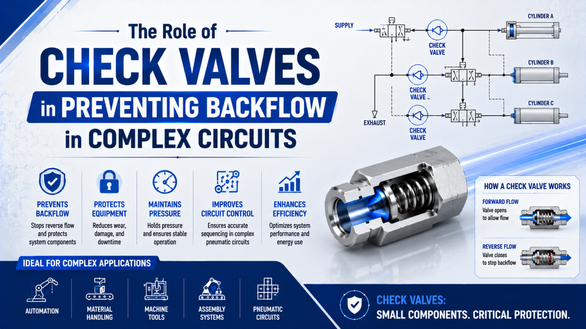
A pneumatic check valve allows flow in one direction and restricts it in the other. In a complex circuit, its real job is more specific: stop a defined pressure source from feeding a branch, accumulator, actuator chamber, or upstream component when the pressure relationship reverses.
That definition matters. A check valve doesn’t manage an entire sequence, guarantee zero leakage, synchronize parallel cylinders, or prove that a suspended load is safe. Start with a marked circuit state, identify every credible reverse-pressure path, and assign one check function to each path. Then test forward loss and reverse leakage separately.
Key Takeaways
- Festo lists 0.1 bar opening differential for specific H-series checks, not for every valve (Festo, 2026).
- Place a check valve against a defined reverse path, not simply “near the cylinder.”
- Pressure retention, controlled release, and hazardous-energy isolation are three different acceptance tests.
Where Can Backflow Start in a Complex Pneumatic Circuit?
Festo gives its H push-in check valves a 0.1 bar minimum opening differential and a 0.2 bar minimum closing differential. Those 2 values show why backflow starts with pressure state, not arrow direction alone: the valve changes state only when the differential crosses its product-specific boundary (Festo H, 2026).
Backflow is reverse movement through a path that the circuit designer intended to be one-way. It can begin whenever a downstream volume becomes the higher-pressure source. That source may be a charged receiver, a loaded cylinder chamber, a higher-pressure branch, thermal expansion in an isolated volume, or air returning from a process connection.
Map at least these four circuit boundaries:
| Circuit boundary | Credible reverse source | What can happen without the intended check function | Design question |
|---|---|---|---|
| Parallel pressure branches | Higher-pressure or faster-decaying branch | One zone feeds another and changes force or timing | Must the branches remain pressure-independent? |
| Receiver or accumulator connection | Stored compressed air | Stored air feeds the supply header or an isolated zone | Where are controlled discharge and maintenance isolation? |
| Regulator outlet | Downstream pressure above the inlet | Pressure reaches a regulator not designed for reverse flow | Does the regulator permit, relieve, or require protection from reverse flow? |
| Loaded actuator chamber | Gravity, external load, or trapped pressure | The actuator drifts or moves when another path vents | Is automatic blocking enough, or is controlled pilot release required? |
A directional valve can create several states around the same check valve. Draw normal motion, stopped motion, supply loss, electrical loss, pilot loss, maintenance exhaust, and restart. Mark the highest-pressure volume in each state. The reverse path may not exist during production, then appear immediately when a shared supply or exhaust zone is isolated.
The useful design document isn’t a list of valve arrows. It’s a reverse-path matrix: one row per operating or fault state, with the high-pressure source, possible destination, required blocked direction, permitted leakage, and release method. That matrix exposes interactions a normal-flow schematic can hide.
For the basic component behavior, use the pneumatic check valve function guide. The rest of this article stays at circuit level: where backflow appears and how to prove the installed protection works.
What Function Should Each Check Valve Perform?
Festo’s HGL pilot-operated check has 2 main ports plus a pilot port, whereas the H family is a 2-port non-return function. That extra pressure input creates a commanded release state; it doesn’t turn a check valve into a directional sequence controller or eliminate leakage and safety checks (Festo HGL, 2026; Festo H, 2026).
Choose the function from the state the circuit needs:
| Required circuit behavior | Suitable function to evaluate | Boundary that still needs engineering |
|---|---|---|
| Automatic flow in one direction, automatic block in reverse | Standard non-return check | Cracking pressure, flow loss, reverse leakage, reseating behavior |
| Retain pressure until a command deliberately releases it | Pilot-operated check | Pilot force, locked-port pressure, release sequence, trapped energy |
| Meter cylinder speed one way and provide freer flow the other | One-way flow-control valve | Needle setting, meter-in or meter-out arrangement, internal check direction |
| Isolate hazardous energy for servicing | Lockable energy-isolating arrangement plus stored-energy controls | A normal check valve isn’t automatically an energy-isolating device |
A standard check valve responds to differential pressure. It doesn’t accept a PLC command. Use it when the desired reverse block should occur automatically whenever the downstream side becomes the higher-pressure side.
A pilot-operated check valve adds a release input. Use it only when the circuit must hold a path closed and later open it under controlled conditions. Festo’s current HGL data, for example, gives 0.5 to 10 bar operating pressure and model-dependent pilot ranges of either 1 to 10 bar or 2 to 10 bar. Those values belong to the listed models, not to every pilot check (Festo HGL, 2026).
A one-way flow controller combines a restriction and a check bypass. Its adjustment knob changes the metered path, while the internal check provides the freer path in the opposite direction. Use the meter-in versus meter-out guide when speed control is the real task.
Don’t use a standard check valve to imitate sequence logic. If one actuator must move only after another reaches pressure or position, define that sequence with sensors, pressure controls, directional logic, and fault handling. A check valve may isolate a branch inside that system, but it cannot verify that the preceding motion finished.
The detailed force balance between ordinary and pilot-released checks is covered in the engineering guide to non-return and pilot-operated check valves. Keeping that calculation there prevents this circuit-placement guide from competing with it.
How Should Check Valves Be Placed in Common Circuit Patterns?
Festo identifies 2 circuit-level purposes for check valves: isolating individual components to prevent mutual pressure effects and preventing units or whole system sections from exhausting after pressure failure. Placement should therefore follow the isolation boundary, while the design separately defines how retained pressure will be released (Festo, retrieved 2026).
Parallel branches
Place a check at a branch inlet when reverse flow from that branch into the shared header or another branch must be blocked. Confirm that normal forward flow still has enough differential to open the valve at maximum coincident demand. A branch check won’t synchronize cylinder position or guarantee equal load sharing.
If several stations share a manifold, map supply and exhaust zones first. A check on one inlet can trap pressure in that zone while another zone vents. The modular pneumatic circuit guide explains how shared galleries, pilot sources, and loss states interact.
Receiver or accumulator branches
An inlet check can stop stored air from feeding back toward a compressor, regulator, or isolated supply section. It doesn’t provide a servicing exhaust path. Show the receiver isolator, relief protection, controlled discharge path, pressure indication, and recharging sequence on the same schematic. The pneumatic accumulator sizing guide covers storage volume and demand separately.
Regulator outlets
Downstream pressure can exceed inlet pressure after upstream isolation, a supply collapse, or external pressurization. Determine whether the selected regulator allows reverse flow, has a relieving function, offers a built-in backflow option, or requires an external arrangement. Don’t add a check blindly: blocking reverse flow can preserve downstream pressure when the intended safe state is to exhaust it.
Cylinder ports
Mounting a pilot-operated check near the actuator can reduce the trapped tube volume between the holding element and cylinder. It still cannot stop motion caused by internal cylinder leakage, mechanical deflection, hose expansion, temperature change, or failure of the load path. Define the acceptable movement and the method of controlled release.
In our experience, placement mistakes are easiest to find by coloring every trapped volume on the circuit drawing. If a colored volume has no rated relief, bleed, monitored release, or servicing procedure, the check valve has created a second problem while solving the first.
How Do Cracking Pressure and Flow Loss Change Circuit Behavior?
Festo’s 2026 H push-in range shows standard nominal flows from 136 to 2,000 L/min across listed sizes, even though those products share a 0.1 bar minimum opening differential. The spread proves that cracking pressure and full-flow capacity are separate selection values (Festo H, 2026).
First calculate the forward differential available before the valve begins opening:
is the pressure difference available across the check valve, is upstream absolute or gauge pressure, and is downstream pressure using the same reference. The valve can begin to open only when the differential reaches the selected manufacturer’s cracking condition.
For a preliminary opening check:
is the tested opening differential for the exact valve under its stated conditions. Reaching it means the moving element has started to lift. It doesn’t mean the valve is fully open or can pass the required production flow with negligible loss.
Use a pressure budget for the complete active path:
is pressure available at the load during flow, is the dynamic supply pressure, and each is the loss through one valve, fitting, tube, manifold passage, regulator, flow control, or exhaust restriction. Use consistent pressure references and manufacturer compressible-flow data.
Consider an illustrative branch with 6.00 bar upstream and 5.85 bar downstream before a check opens. The available differential is 0.15 bar. A model with a 0.10 bar cracking value can begin opening, but only 0.05 bar remains before considering its rising flow loss and the rest of the path. Passing the cracking check alone would be misleading.
ISO 6358-1 specifies steady-state testing for pneumatic component flow characteristics using compressible fluids. It also excludes components such as cylinders and accumulators that exchange energy with the fluid during measurement, so catalogue component flow data shouldn’t be presented as a complete moving-machine prediction (ISO 6358-1, confirmed 2022).
The pneumatic valve pressure-drop guide explains compressible-flow assumptions in more detail. Confirm the final model with the manufacturer’s flow curve or ISO 6358 data at the real upstream pressure, downstream pressure, and required flow.
Why Must Reverse Leakage and Load Holding Be Tested Separately?
SMC states that its ASP pilot check and actuator aren’t guaranteed for zero air leakage and recommends a mechanical holding method when long-term position retention is required. It also warns that 50% pilot pressure may still fail to release the check in some balance-control circuits (SMC ASP, 2024).
Reverse leakage is air that passes the closed check boundary under a stated reverse differential, temperature, and test duration. Load holding is the resulting machine motion under gravity, external force, trapped pressure, seal leakage, structural compliance, and the defined fault state. One is a valve or circuit leakage test; the other is a machine safety and performance test.
Pressure decay doesn’t identify the leaking component by itself. A test boundary may contain the check valve, tubing, fittings, instruments, directional valve, and cylinder seals. Shrink the boundary or measure flow at a defined reverse pressure before blaming the check valve.
SMC also warns that residual pressure can cause an actuator to move suddenly during maintenance. Its product guidance says that a pilot check may fail to release in a balance circuit even when pilot pressure is 50% of operating pressure, and pilot pressure may need to equal operating pressure in that case. Use the selected product’s release curve and installed measurements, not a universal ratio.
OSHA 29 CFR 1910.147 covers pneumatic energy where unexpected startup or release of stored energy could injure employees. After lockout or tagout is applied, potentially hazardous stored or residual energy must be relieved, disconnected, restrained, or otherwise rendered safe, with continued verification where reaccumulation is possible (OSHA 1910.147, retrieved 2026).
Write three different pass limits: maximum reverse leakage, maximum permitted load movement over a defined time, and the verified safe state for servicing. Combining them into “the valve holds” hides which boundary actually passed.
For a suspended or externally loaded actuator, consider mechanical blocking, rod locks, brakes, counterbalance arrangements, or other engineered restraints as required by the risk assessment. A check valve can be one layer. It isn’t evidence that the complete safety function has been validated.
Commissioning: Test the Circuit in Both Directions
ISO 6358-1 defines 1 steady-state framework for component flow testing, while ISO 4414 covers design, installation, adjustment, operation, maintenance, reliability, and safety of pneumatic systems. Commissioning therefore needs 2 separate baselines: forward loss at production flow and reverse leakage at a controlled differential (ISO 6358-1, 2013; ISO 4414, confirmed 2021).
Forward-flow test
Run the worst credible combination of simultaneous air demands. Measure pressure immediately upstream and downstream of the check valve with instruments fast enough for the event. Record flow or actuator demand, supply pressure, downstream pressure, load, valve orientation, air temperature, and cycle state.
A static gauge reading isn’t enough. The branch may show full regulator pressure while stopped, then lose differential as soon as several actuators demand flow. Compare the measured loss with the selected valve’s published curve and with the pressure budget required by the downstream function.
Reverse-leakage test
Place the circuit in the defined blocked state, apply the approved reverse differential, allow temperature to stabilize, and measure decay or leakage flow over a stated time. Identify every component inside the test boundary. Mechanically secure any load before changing connections or isolating smaller sections.
Pilot-release test
For a pilot-operated check, measure pilot pressure at the valve, locked-port pressure, valve-side pressure, release time, and initial actuator movement. Repeat at minimum supply, maximum credible load pressure, maximum exhaust back pressure, and each relevant loss state. Confirm that release establishes controlled motion rather than dumping a loaded chamber into a low-pressure path.
Fault-state test
Test main-air loss, pilot-air loss, electrical loss, emergency stop, branch isolation, restart, and maintenance exhaust separately. Record which volumes remain pressurized and whether any pressure can reaccumulate. Restore energy only through the approved sequence.
Use a symptom table to keep diagnosis evidence-based:
| Symptom | Check-valve mechanism to investigate | Other causes to exclude | Measurement |
|---|---|---|---|
| Slow forward motion | High cracking differential, small passage, contamination | Tube, fitting, directional valve, regulator, exhaust restriction | Dynamic pressure on both sides |
| Branch pressure decays | Seat leakage, contamination, incomplete reseating | Fittings, cylinder seals, instruments, venting regulator | Smaller isolated boundaries |
| Chatter | Marginal or pulsating differential | Regulator instability, compressor pulsation, vibration | Time-aligned pressure traces |
| Pilot check won’t release | Insufficient pilot force or back pressure | Wrong porting, blocked pilot tube, directional state | Pilot and locked-port pressures |
| Load moves after stop | Reverse leakage or unintended release | Cylinder leakage, hose expansion, structural movement | Secure load, then test each boundary |
Don’t set universal monthly, annual, or 2-year replacement intervals. Build maintenance from the exact component documentation, cycle count, contamination history, leakage trend, machine risk, and known-good commissioning values.
A Seven-Check Backflow Prevention Workflow
OSHA 1910.147(d)(5) and (d)(6) impose 2 separate servicing duties: render hazardous stored energy safe and verify isolation. Apply the same separation during design review. A check valve may control a reverse path during operation, but stored-energy control and verification still need explicit hardware, procedures, and acceptance evidence (OSHA, retrieved 2026).
The released circuit record should include the schematic revision, valve manufacturer and model, free-flow arrow, cracking data, published flow characteristic, reverse-leakage limit, pilot data where applicable, test pressure, measurement points, load condition, fault states, servicing method, and approved substitute.
If a replacement changes any of those fields, it isn’t automatically equivalent because the threads fit. Repeat the affected forward-flow, reverse-leakage, pilot-release, and safety tests.
Pneumatic Check Valve Backflow FAQs
The 5 answers below use Festo’s model-specific 0.1 bar opening example and SMC’s warning that 50% pilot pressure may still fail to release a balance circuit. Together, they show why valve direction, flow capacity, leakage, pilot release, and stored energy must be verified independently (Festo, 2026; SMC, 2024).
What is the difference between cracking pressure and full-flow pressure drop?
Cracking pressure is the differential at which the check element begins to open. Full-flow pressure drop is the loss while the required production flow passes through the opened valve. Festo’s H range lists 0.1 bar opening differential but model flows from 136 to 2,000 L/min, demonstrating that the values aren’t interchangeable.
Where should a check valve be installed in a parallel pneumatic circuit?
Install it at the branch boundary where reverse flow must be blocked, then verify the intended free-flow direction and dynamic pressure margin. Don’t place it by proximity alone. Also identify trapped volumes and a controlled release path, because isolating one branch can retain pressure after the shared header or another zone exhausts.
Can a standard check valve hold a vertical cylinder safely?
Not by category name alone. SMC states that pilot checks and actuators aren’t guaranteed for zero leakage and recommends mechanical holding when long-term retention is required. A vertical-load design needs defined leakage, permitted movement, fault-state behavior, controlled release, mechanical restraint where required, and machine-specific risk assessment.
Why can a pilot-operated check valve fail to release?
Pilot force may be insufficient against locked-port pressure, spring force, friction, or back pressure. SMC warns that 50% pilot pressure can still fail in some balance-control circuits and may need to equal operating pressure. Measure pilot and locked-port pressure at the valve and follow the selected model’s release data.
How should reverse leakage be tested?
Apply a defined reverse pressure, stabilize temperature, and measure leakage flow or pressure decay for a stated time. List every component inside the boundary. Secure loaded machinery mechanically before testing. If pressure falls, isolate smaller boundaries so leakage through the check valve isn’t confused with cylinder seals, fittings, tubing, or instruments.
Sources and technical references
- ISO 4414:2010, Pneumatic Fluid Power General Rules and Safety Requirements, confirmed 2021, retrieved July 22, 2026.
- ISO 6358-1:2013, Steady-State Flow Testing for Pneumatic Components, confirmed 2022, retrieved July 22, 2026.
- Festo, Check Valve H, HA, HB Datasheet, April 2026.
- Festo, Piloted Check Valve HGL Datasheet, June 2026.
- Festo, Check Valve Application Overview, retrieved July 22, 2026.
- SMC, ASP Series Speed Controller with Pilot Check Valve, 2024 catalogue, retrieved July 22, 2026.
- OSHA 29 CFR 1910.147, Control of Hazardous Energy, retrieved July 22, 2026.