

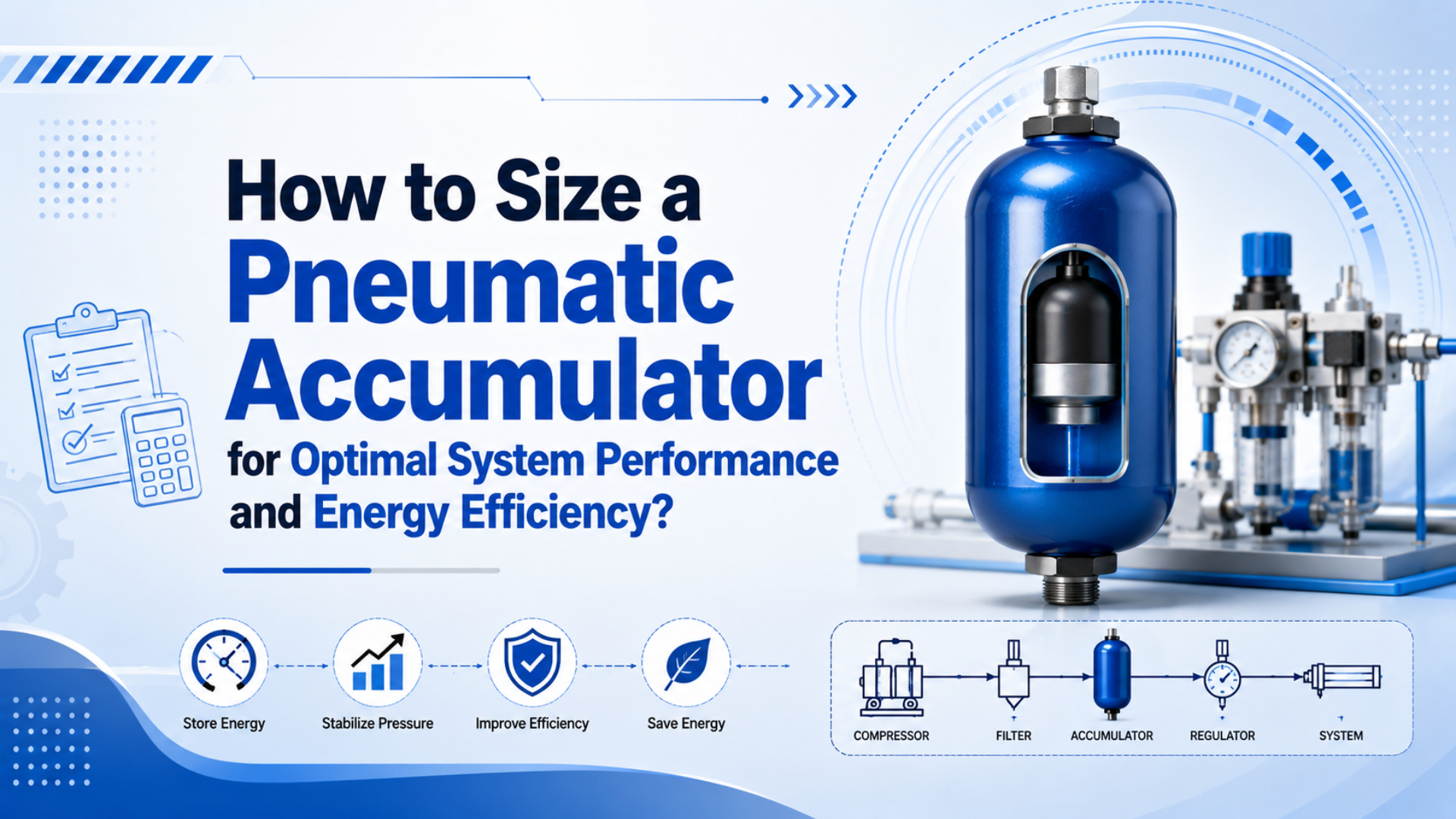
Size a pneumatic accumulator by calculating the short-term air demand that the compressor and piping cannot supply, then matching that storage to an allowed pressure drop. DOE lists “Receiver Tank Sizing” as a compressed-air calculator in MEASUR, and CAGI says well-designed systems should hold pressure drop to 10% or less from compressor discharge to point of use (DOE MEASUR, 2026; CAGI, 2026).
In shop-floor language, a pneumatic accumulator, often an air receiver tank, buys time. It buffers a fast cylinder bank, blow-off event, fixture release, or tool burst so the local pressure doesn’t fall below the machine’s usable limit before the compressor catches up.
Key Takeaways
- Size from peak event flow, event duration, compressor support flow, and allowed pressure swing.
- CAGI’s 10% pressure-drop target keeps receiver sizing tied to real point-of-use pressure.
- OSHA receiver rules require drains, gauges, safety valves, and accessible installation before any volume calculation is enough.
The useful split is simple: the compressor supplies repeated average demand, the receiver covers short peaks, and the piping must pass the burst without wasting the stored air as pressure drop. If you only size the tank, you’re solving one-third of the problem.
What Problem Does a Pneumatic Accumulator Actually Solve?
A pneumatic accumulator solves short-duration demand mismatch, not a permanently undersized air system. CAGI says excess pressure drop often pushes operators to raise compressor discharge pressure, and every extra 2 psig can add about 1% compressor power consumption (CAGI, 2026).
That means the first job is not “buy a bigger tank.” The first job is to identify the event that pulls pressure down: a group of pneumatic cylinders, a blow-off manifold, a fixture bank, a valve dump, or a tool that opens for a few seconds at a time.
An accumulator is useful when the event is short enough for storage to cover and the compressor has time to recover before the next event. If the average demand is above compressor capacity, a receiver only delays the pressure crash. It doesn’t remove the capacity problem.
Use a receiver when you see one of these patterns. If the issue appears as short pressure sag rather than pure storage shortage, use the related pressure fluctuation troubleshooting guide before increasing receiver size.
| Symptom | What it usually means | First check |
|---|---|---|
| Pressure dips only during one machine step | Short peak demand exceeds local supply | Event flow and duration |
| Compressor short-cycles at low average demand | Storage or pressure band may be too small | Receiver volume and controls |
| A distant actuator slows during another station’s cycle | Header, branch, or point-of-use pressure drop | Dynamic pressure at the actuator |
| Blow-off or cleaning station weakens other machines | One high-flow event is stealing local pressure | Secondary receiver near the station |
| Pressure is stable at the compressor but low at the tool | Local restriction or undersized line | Filter, regulator, valve, tube, fitting |
For actuator-specific air use, pair this article with pneumatic flow-rate calculation. Flow tells you the demand. The accumulator tells you how long you can support that demand inside a pressure band.
Size From Peak Demand, Not Average CFM
DOE’s sourcebook says pressure and flow data over time can reveal intermittent loads, disruptions, leaks, and storage needs. A single pressure profile is not enough; data logging over a real production period gives the complete picture (DOE Sourcebook, 2016).
Average CFM can hide the problem. A machine that averages 200 L/min may need 900 L/min for 12 seconds when the clamp, ejector, and reject cylinder all fire together. The receiver should be sized for that event window, after subtracting whatever compressor or upstream line flow can support during the same window.
In our experience, bad accumulator sizing usually starts with a bad timing diagram. Someone adds every device on the machine, or they use the shift average. Neither number tells you what happens in the three seconds when the line actually sags.
Build the worksheet like this:
| Input | Unit | How to get it |
|---|---|---|
| Peak demand flow | L/min, m3/min, or SCFM free air | Sum simultaneous devices during the problem event |
| Compressor support flow | Same unit as demand | Use realistic available flow during the event, not nameplate only |
| Event duration | Seconds or minutes | Measure how long the high-demand window lasts |
| Receiver high pressure | psig, bar gauge, or kPa gauge | Cut-out, unload, or stable pre-event pressure |
| Minimum usable pressure | Same pressure unit | Lowest pressure the machine can tolerate at point of use |
| Recovery time | Seconds or minutes | Time available before the next peak event |
| Safety and reserve margin | Percent | Add after calculation, usually 20% for preliminary selection |
CAGI’s sizing case study shows why measured demand matters. A site with two 250 hp compressors had 2,436 cfm total capacity, but the assessment found only 418 cfm average flow and 535 cfm peak flow, while the 1,040 gallon receiver was still undersized (CAGI Sizing Case Study, 2026). The system had capacity on paper and a storage/control problem in practice.
How Do You Calculate the Required Accumulator Volume?
The receiver sizing equation in the DOE sourcebook uses time, air demand, atmospheric pressure, and the difference between high and low receiver pressure. When supply can support part of the event, DOE shows the demand term as C - S, not just total demand (DOE Sourcebook, 2016).
Use this preliminary formula for a short peak event:
V = T x (C - S) x Pa / (P1 - P2)

where:
V  = receiver volume
T  = event duration
C  = peak free-air demand during the event
S  = support flow available during the event
Pa = atmospheric pressure
P1 = receiver high pressure
P2 = minimum usable receiver pressure
Keep units consistent. If flow is in SCFM, time should be in minutes and volume comes out in cubic feet. If flow is in L/min, time should be in minutes and pressure must be handled with the same absolute-pressure basis. The pressure difference can be a gauge-pressure difference, but the atmospheric pressure term must match the pressure unit.
NIST lists 1 psi as 6,894.757 Pa, and standard atmospheric pressure as 101,325 Pa (NIST, 2025). For U.S. shop calculations, 14.7 psia is the usual atmospheric-pressure approximation.
Gauge pressure + atmospheric pressure = absolute pressure

100 psig + 14.7 psi = 114.7 psia
80 psig + 14.7 psi = 94.7 psia
Why not size from absolute high and low pressures directly? You can, if your formula and units are consistent. The practical error is mixing gauge pressure in one part of the calculation and absolute pressure in another. That error can make a receiver look smaller or larger than it really is.
Worked Example: 800 L/min Demand for 20 Seconds
DOE’s MEASUR tool list includes 44 calculator entries, including receiver tank sizing as a compressed-air calculation, and the same mass-balance logic fits a quick plant-floor estimate. Start with net storage demand, then add reserve after the result (DOE MEASUR, 2026).
Assume a packaging station needs a short burst:
| Parameter | Value |
|---|---|
| Peak event demand, C | 800 L/min free air |
| Compressor or branch support, S | 300 L/min free air |
| Net storage demand, C - S | 500 L/min |
| Event duration, T | 20 s, or 0.333 min |
| Receiver high pressure, P1 | 8 bar gauge |
| Minimum usable pressure, P2 | 6 bar gauge |
| Atmospheric pressure, Pa | 1.013 bar |
Calculation:
V = T x (C - S) x Pa / (P1 - P2)
V = 0.333 min x 500 L/min x 1.013 bar / (8 bar - 6 bar)
V = 84.4 L

Add 20% reserve:
84.4 L x 1.20 = 101.3 L
Select the next suitable standard receiver size after checking pressure rating, local codes, drain access, relief-valve capacity, and the real recovery time. In this example, a 100 L receiver may be a reasonable first-pass size only if the compressor can refill it before the next high-demand event and the local line can pass the flow.
If support flow is zero:
V = 0.333 x 800 x 1.013 / 2 = 135.0 L

With 20% reserve:
135.0 x 1.20 = 162.0 L
That comparison matters. If you count compressor support that the branch line cannot actually deliver, the receiver will be undersized. If you ignore real support flow, the receiver may be larger than needed.
How Should You Choose the Pressure Band?
CAGI says a well-designed compressed-air system should have no more than 10% pressure drop between compressor discharge and point of use. The DOE sourcebook also warns that each 2 psi increase near 100 psig can add about 1.6-2% total energy use when artificial demand is included (CAGI, 2026; DOE Sourcebook, 2016).
A wider pressure band gives more usable stored air. It also gives the machine more pressure variation. That trade-off is fine for some blow-off and tool applications. It can be risky for clamping, gauging, forming, or any cylinder motion where the usable force margin is tight.
Use this decision path:
| Pressure-band choice | Benefit | Risk | Good fit |
|---|---|---|---|
| Narrow band, such as 7.0 to 6.5 bar | Stable point-of-use pressure | Larger receiver or more cycling | Clamp force, precision motion |
| Medium band, such as 8.0 to 6.0 bar | Balanced storage and stability | Needs regulator and port checks | Packaging, fixture banks |
| Wide band, such as 10.0 to 6.0 bar | More stored air per liter | Higher upstream pressure cost | Emergency reserve, isolated burst loads |
Check the downstream regulator too. A receiver at 8 bar is useful only if the regulator, filter, valve, tube, and fittings can deliver enough flow while staying above the machine’s minimum pressure. For cylinder circuits, review working pressure at the actuator, not only compressor discharge pressure.
If you’re tempted to raise the compressor setpoint, ask a harder question: is the receiver too small, or is pressure being wasted across a dirty filter, undersized quick disconnect, small tube, or restricted valve? Raising the header hides those problems and makes every leak more expensive.
Where Should the Accumulator Be Installed?
Atlas Copco describes an air receiver as temporary storage for demand peaks, and its sizing article gives a rule of thumb of 3-4 gallons per CFM, or 10-15 liters per liter per second, while warning that the actual application still matters (Atlas Copco, 2026).
Use the rule of thumb only as a sanity check. For a machine with short, sharp bursts, calculate the local receiver from the event. For a compressor room receiver, check compressor controls, dryer behavior, system volume, leak load, and pressure band. The same tank volume can behave differently in those two locations.
Primary receiver placement:
- Near the compressor room, usually around the compressor, dryer, and main distribution path.
- Useful for compressor control stability, cooling, moisture separation, and system-level buffering.
- Must be accessible for inspection, draining, gauges, relief valves, and service.
Secondary receiver placement:
- Near a high-demand machine, fixture bank, blow-off station, or long branch end.
- Useful when the main system pressure is acceptable but a local event pulls the branch down.
- Should be installed with a regulator, check valve if appropriate, drain, pressure gauge, and safe isolation procedure.
DOE recommends reducing pressure drops or adding secondary storage before increasing compressor capacity or discharge pressure when point-of-use pressure is low (DOE Sourcebook, 2016). That is the practical order: measure, remove restrictions, add local storage, then revisit compressor settings.
For long-stroke or high-speed cylinder layouts, local storage may sit near a rodless cylinder or valve manifold. The local receiver does not replace proper valve sizing. It simply makes sure the valve has stored air close enough to use.
Safety and Maintenance Checks Before You Buy
OSHA 29 CFR 1910.169 requires air receivers to have a drain at the lowest point, a visible pressure gauge, and one or more spring-loaded safety valves. OSHA also says the relief capacity must keep receiver pressure from exceeding maximum allowable working pressure by more than 10% (OSHA, current as of 2026).
Do this before treating a calculated volume as a purchase size:
| Check | Why it matters |
|---|---|
| Pressure rating and code | The receiver must be rated above system pressure and meet local pressure-vessel requirements |
| Relief valve | Protects against overpressure if controls fail |
| No valve between receiver and relief valve | OSHA prohibits blocking the safety valve path |
| Drain at the lowest point | Removes accumulated oil and water |
| Visible gauge | Lets operators see pressure during charging and discharge |
| Accessible installation | Drains, handholes, manholes, and valves need service access |
| Isolation and lockout procedure | Maintenance must not depend on memory or informal habits |
| Internal corrosion review | Wet air receivers need drainage and inspection discipline |
Moisture is not a footnote. A receiver cools compressed air, and cooling condenses water. If the receiver is not drained, that water can corrode the vessel and carry downstream into FRL units, valves, tubing, and cylinders.
What about oversizing? A larger receiver can smooth pressure, but it also takes more space, costs more, may increase startup fill time, and can collect more condensate if drainage is neglected. The right size is the smallest safe, code-compliant receiver that covers the measured event and recovers before the next one.
When Is a Bladder or Diaphragm Accumulator Worth Considering?
Most plant-air applications start with a receiver tank, while specialty accumulators make sense when response time, contamination separation, or tight mounting space matters more than low cost per liter. Atlas Copco notes tank-mounted compressors are usually limited to smaller systems up to about 26 kW or 35 hp because larger packages can become top-heavy (Atlas Copco, 2026).
Use a receiver tank for ordinary compressed-air storage. Use another accumulator style only when the application has a specific reason.
| Accumulator type | Best use | Sizing note |
|---|---|---|
| Receiver tank | General plant air, peak buffering, compressor control | Lowest cost per stored volume, safety code still governs |
| Point-of-use receiver | Local short bursts near one machine | Size from event flow and branch support |
| Bladder accumulator | Fast response or separated media in specialty systems | Effective usable volume depends on bladder design |
| Diaphragm accumulator | Compact pulsation damping or clean separation | Check diaphragm material, pressure rating, and service access |
| Piston accumulator | Higher-pressure or specialized separation tasks | Seal friction and maintenance change the selection |
For most Bepto-style pneumatic cylinder systems, the sizing question is not “receiver or exotic accumulator?” It is “how much local compressed-air storage does this event need, and can the compressor rebuild that storage before the next cycle?”
If the shape of a custom chamber is part of the problem, the companion article on flat-sphere volume in pneumatic accumulator chambers covers geometry. This article covers air-system storage behavior.
FAQs About Pneumatic Accumulator Sizing
FAQ answers should stay tied to measured demand and safety requirements. OSHA’s receiver rule covers drains, gauges, safety valves, and access, while CAGI’s pressure-drop guidance keeps the sizing decision connected to the point-of-use system instead of tank volume alone (OSHA, current as of 2026; CAGI, 2026).
How do I know if my pneumatic accumulator is properly sized?
A properly sized accumulator holds point-of-use pressure above the machine’s minimum during the peak event and recovers before the next event. Log pressure near the actuator or tool during production. If pressure still sags below the usable limit, either storage, branch flow, regulator capacity, or compressor recovery is still short.
Can I use multiple smaller receivers instead of one large receiver?
Yes, multiple receivers can work well when demand is distributed. Use a main receiver for compressor control and smaller point-of-use receivers near high-demand stations. Check isolation, relief valves, drains, and pressure gauges for each receiver. The piping between receivers still has to pass the required flow.
What happens if I oversize a pneumatic accumulator?
Oversizing usually improves pressure stability, but it can waste floor space, raise cost, extend startup fill time, and increase condensate volume that must be drained. Oversizing also doesn’t fix a restricted valve, clogged filter, undersized tube, or compressor that cannot recover before the next peak event.
Should accumulator sizing use gauge pressure or absolute pressure?
Use a consistent pressure basis. For receiver mass-balance calculations, atmospheric pressure is part of the formula, so gauge values must be handled carefully. NIST lists standard atmospheric pressure as 101,325 Pa and 1 psi as 6,894.757 Pa, which supports common conversions between psig, psia, bar, and kPa.
Is an air receiver enough for emergency backup?
Sometimes, but only after a risk review. Emergency backup storage must cover required flow, required time, minimum pressure, safe shutdown sequence, and code-compliant receiver hardware. If gravity, stored energy, or personnel safety is involved, use mechanical locks, safe exhaust, brakes, or engineered safety circuits rather than air storage alone.
Sources
-
DOE: Improving Compressed Air System Performance, Third Edition, pressure drop, storage, data logging, artificial demand, and receiver sizing method. Retrieved 2026-06-04.
-
DOE: MEASUR Calculator List and Descriptions, compressed-air receiver tank sizing, usable air capacity, pneumatic air requirement, and system capacity calculators. Retrieved 2026-06-04.
-
CAGI: Working With Compressed Air, 10% pressure-drop guidance and 2 psig energy rule. Retrieved 2026-06-04.
-
CAGI: Case Study - Sizing, measured average flow, peak flow, installed compressor capacity, receiver undersizing, and annual savings example. Retrieved 2026-06-04.
-
OSHA: 29 CFR 1910.169 Air Receivers, drain, gauge, safety valve, accessibility, and relief-capacity requirements. Retrieved 2026-06-04.
-
NIST: Pressure and Gas Flow Unit Conversions, pressure unit conversions and standard atmospheric pressure reference. Retrieved 2026-06-04.
-
Atlas Copco: What Is an Air Receiver?, receiver role, sizing rule of thumb, configuration, pressure, and maintenance notes. Retrieved 2026-06-04.