

Select a valve for high-frequency cycling from the exact part number’s switching frequency, shifting time, duty rating, flow data, pressure range, temperature limits, and tested life. Don’t start with labels such as “fast valve” or “100-million-cycle valve.” A valve can have a long statistical life yet be too slow for the machine, or switch quickly but overheat in the intended duty.
The range between real products is wide. Festo lists a maximum switching frequency of 500 Hz for one MHJ10 high-speed valve, while a standard VUVG directional-valve model is listed at 2 Hz. Those figures are not a brand comparison. They show why a valve family, seal material, or port size cannot substitute for model-specific data (Festo MHJ10; Festo VUVG, retrieved July 22, 2026).
Key Takeaways
- A machine cycle and a valve shift are not the same; one extend-and-retract sequence can create two shifts.
- One Festo MHJ10 model is rated at 500 Hz, while ordinary directional valves may be limited to a few hertz.
- Verify response, frequency, coil duty, flow, pressure, temperature, and tested life separately.
- Prove the selection under the machine’s worst operating conditions.
High-frequency cycling valve selection is the process of matching a valve’s validated switching and life limits to the command pattern and pneumatic load of one machine. The result should be traceable to an exact model, catalog revision, test condition, and acceptance test.
What Does High-Frequency Cycling Mean for This Machine?
Festo’s MHJ10 example is rated at 500 Hz, but its operating notes also specify pressure, voltage, temperature, mounting, and “do not operate without flow” conditions (Festo MHJ10, retrieved July 22, 2026). “High frequency” therefore has no useful universal threshold until the machine event and valve function are defined.
Begin with what the valve must do. Is it a 3/2 valve pulsing an air jet, a 5/2 valve reversing a double-acting cylinder, a vacuum valve controlling an ejector, or a proportional valve modulating flow? These applications can share a cycle rate yet impose very different loads on the coil, pilot stage, spool, seals, exhaust path, and downstream equipment.
Record the operating sequence before opening a catalog:
| Machine input | What to record | Why it changes selection |
|---|---|---|
| valve function | 2/2, 3/2, 5/2, 5/3, normal state, mono- or bistable | establishes the required flow paths and switching states |
| command pattern | on-time, off-time, bursts, dwell, simultaneous outputs | determines electrical and thermal duty |
| pressure | minimum dynamic inlet, maximum inlet, pilot pressure | affects shifting force, response, and available actuator force |
| flow path | supply, working ports, exhaust, tube ID and length | affects chamber fill and exhaust time |
| environment | ambient and media temperature, vibration, ingress, contaminants | changes allowable frequency and wear conditions |
| failure state | air loss, power loss, emergency stop, restart | defines the safe valve architecture and reset behavior |
Thousands of production cycles per hour may sound severe, but 1,000 machine cycles per hour is only 0.278 cycles per second. The valve may shift once, twice, or several times during each machine cycle. Count those shifts directly. That’s the demand the datasheet and reliability evidence must cover.
A production counter and a valve counter answer different questions. The production counter measures finished machine cycles. The valve counter should measure commanded state changes at the output that drives the valve. Keeping both values exposes extra diagnostic pulses, reject sequences, manual jogging, and restart actions that a simple units-per-hour estimate misses.
How Do You Convert Machine Production Into Valve Operations?
One Festo MFH reliability sheet reports a B10 value of 80 million cycles and a maximum switching frequency of 3 Hz for the tested valve configuration (Festo MFH reliability data, retrieved July 22, 2026). The two figures must be checked independently: one describes a population reliability result, while the other limits operating rate.
If one machine cycle commands valve shifts and takes seconds, the average command frequency is:
Here, is average valve shifts per second, is shifts per machine cycle, and is machine-cycle time in seconds. Average frequency alone is not enough for a bursty sequence, so also calculate the shortest interval between consecutive commands.
Annual valve demand can be estimated from production rate:
In this equation, is valve shifts per year, is machine cycles per hour, is operating hours per day, and is operating days per year. Confirm whether the manufacturer’s “cycle” means one change of state, an on-off pair, or another defined sequence before comparing the result with a catalog life value.
Consider a double-acting station running 30 machine cycles per minute. If each cycle requires one extension and one retraction, the valve makes 60 state changes per minute, or 1 Hz. At 16 hours per day and 300 days per year:
This station needs 17.28 million state changes per year before setup, faults, and manual cycles are added. A nominal 80-million-cycle B10 value would not automatically mean 4.6 maintenance-free years. B10 is a statistical reliability point under stated test conditions, not a warranty or an installed-life promise.
ISO 19973-2:2015 provides test and reporting procedures for directional-valve reliability. It states that valve lifetime is usually expressed in cycles and applies a first-failure method without repairs, excluding outliers under its defined method (ISO 19973-2:2015, confirmed current in 2026). Ask for the test definition, sample basis, threshold, medium, pressure, frequency, and failure criteria behind any life claim.
Which Valve Ratings Must Be Compared Separately?
At 4 bar and 24 V in new condition, one Festo MHJ10 variant lists 1.2 ms switch-on time, 0.6 ms switch-off time, and 500 Hz maximum switching frequency (Festo MHJ10, retrieved July 22, 2026). These are three separate ratings. None can be inferred from another.
| Catalog item | Question it answers | What it does not prove |
|---|---|---|
| shifting time | how long the valve takes to change state under a defined test | maximum sustainable command rate or actuator stroke time |
| maximum switching frequency | how rapidly that model may be commanded under stated conditions | long statistical life or acceptable coil temperature in every manifold |
| duty rating | how long the coil may remain energized under specified conditions | unlimited mechanical shifting or flow capacity |
| cycle-life or B10 result | how the tested population behaved under a reliability procedure | identical life with different air quality, pressure, load, or temperature |
| Cv, Kv, or ISO 6358 data | how much flow the valve passes under defined pressure conditions | electrical response or mechanical endurance |
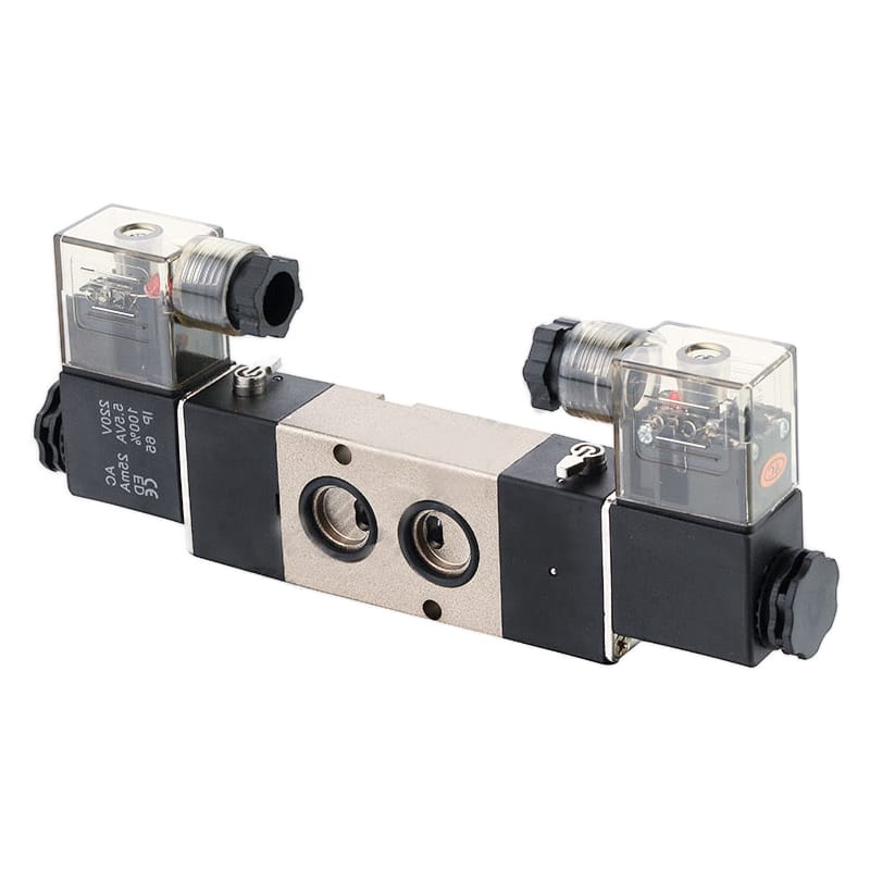
A product photograph confirms form factor, not switching frequency or cycle life. Use the exact part number and manifold configuration for every rating.
Don’t add valve shifting time directly to catalog cylinder stroke time without defining measurement boundaries. ISO 12238:2023 specifies shifting-time procedures for electrically or pneumatically operated directional valves with two or three positions (ISO 12238:2023, 2023). Tube filling, chamber pressure rise, exhaust, cylinder travel, sensor delay, PLC scanning, and downstream interlocks occur outside the valve’s shifting interval.
The detailed solenoid valve response-time measurement guide explains how to separate the electrical command, valve pressure change, and actuator motion. Use the AC versus DC coil comparison when supply type, inrush behavior, suppression, or dropout timing is the unresolved variable.
Which Valve Mechanism and Seal Fit the Duty?
SMC publishes 200 million cycles for the metal-seal version and 70 million cycles for the rubber-seal version of its SY3000/5000/7000 family (SMC Web Catalog, retrieved July 22, 2026). Those family-specific values show a tradeoff, not a rule that metal seals always outperform elastomers in every application.
Choose the valve mechanism from the required function and operating envelope:
- Direct-acting poppet or spool: avoids a separate pilot-pressure requirement and can suit small-flow, fast events. Coil force, orifice size, electrical power, and pressure load still limit the design.
- Pilot-operated directional valve: can control a larger main stage with modest pilot power, but minimum pressure differential, pilot passages, contamination, and exhaust back pressure can affect shifting.
- Bistable or double-solenoid valve: can hold its last commanded state without continuous coil power, but the retained state must be acceptable during power loss and restart.
- Proportional valve: belongs in the comparison only when variable flow or pressure is required. It is not automatically a faster substitute for an on-off directional valve.
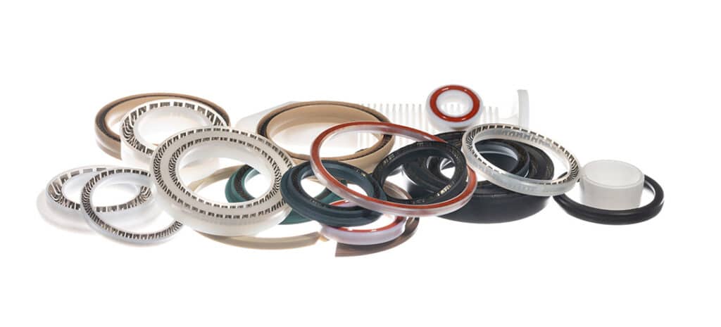
Seal material is one input. Geometry, surface finish, lubrication policy, leakage class, pressure, temperature, speed, and contamination decide how the sealing system behaves.
Metal-seal spools can reduce sliding-seal wear, yet their permitted internal leakage and sensitivity to fine contamination may differ from a soft-seal valve. Elastomer seals can provide tight shutoff, but friction, compression set, swelling, temperature, and lubricant compatibility need review. PTFE, HNBR, NBR, FKM, and polyurethane aren’t interchangeable labels.
Ask the supplier for the exact seal material and sealing principle. Then compare permissible leakage, air-quality class, lubricated or non-lubricated operation, temperature range, pressure range, and service instructions. A general material claim without the valve design and test condition isn’t enough for selection.
Can the Pneumatic Path Keep Up With the Valve?
Festo lists one VUVG valve at 2 Hz with 14 ms switch-on and 17 ms switch-off times, despite a 100% duty cycle (Festo VUVG, retrieved July 22, 2026). Continuous energization permission therefore does not establish fast cycling, and fast electrical shifting does not guarantee rapid cylinder motion.
The valve must pass enough supply and exhaust flow at the actual pressures. Check both directions through the selected function. A 5/2 valve can have different supply-to-working-port and working-port-to-exhaust performance, and the installed manifold, fittings, tubing, flow controls, quick-exhaust valves, and silencers can become the dominant restriction.
Use the high-flow solenoid valve guide for rapid-cycle assembly when the open question is Cv, ISO 6358 flow data, or cylinder stroke flow. This article keeps the focus on switching duty and reliability rather than duplicating that sizing workflow.
Measure dynamic pressure at the valve inlet and both actuator ports during the worst machine sequence. A static regulator gauge can look healthy while local pressure collapses during simultaneous demand. Likewise, a delayed return stroke may be caused by exhaust back pressure rather than slow valve shifting.
In our experience, when a machine report says “the valve cannot cycle fast enough,” the first useful step is splitting the timeline into command, outlet-pressure response, cylinder-port pressure, motion, and sensor confirmation. That trace often shows whether a faster valve is justified or whether tube volume, a clogged silencer, cushioning, load friction, or the control program owns most of the delay.
Thermal and Electrical Limits Belong in the Selection
One Festo MHJ10 HF/LP variant combines a 7 W high-current phase with a 2 W low-current phase and is listed for 100% duty; its environmental and media temperature limits still vary with switching frequency (Festo MHJ10 HF/LP, retrieved July 22, 2026). “100% duty” is not permission to ignore temperature.
For a repetitive command with coil on-time and command period , electrical duty is:
Here, is energized duty in percent. Calculate it for the most demanding production window, including long holds and fault states. A station can have a modest switching frequency but nearly continuous coil energization, or high burst frequency followed by a long cooling interval.
Check these electrical details on the exact option code:
- nominal voltage and permitted voltage tolerance at the valve connector
- steady current, peak current, and power-saving or peak-and-hold behavior
- maximum continuous on-time and any pulsed-duty definition
- built-in flyback, TVS, rectifier, LED, or surge suppressor
- PLC output current, off-state leakage, cable voltage drop, and connector rating
- dropout-time effect of the suppression circuit
- ambient-temperature and manifold-density derating
Closely packed manifolds can run hotter than individually mounted valves. Measure coil or surface temperature after thermal equilibrium at the production command pattern, not after a short bench test. Also verify the permitted test pulses from safety outputs; diagnostic pulses can create unintended movement on a fast, low-power input.
How Should You Validate the Candidate at the Machine?
ISO 12238:2023 covers shifting-time measurement for monostable and bistable pneumatic directional valves with two or three positions (ISO 12238:2023, 2023). Use that boundary for valve comparison, then extend the machine acceptance test through port pressure, actuator motion, sensor arrival, temperature, leakage, and safe restart.
Run the test at the least favorable permitted conditions, not only at nominal pressure on a workbench:
- minimum dynamic supply and pilot pressure
- maximum operating pressure
- lowest and highest allowed supply voltage
- highest ambient and compressed-air temperature
- full manifold population and the real enclosure airflow
- normal tube lengths, fittings, flow controls, and exhaust silencers
- production load, cushion settings, and simultaneous station demand
- cold start, warm steady state, stop, restart, and fault recovery
Capture command voltage or current, valve-outlet pressure, actuator-port pressure, position or sensor timing, and temperature on the same time base. Report opening and closing separately. If the machine uses bursts, test the burst rate, burst length, and recovery interval rather than averaging them into one frequency.
A defensible acceptance limit has two layers. The valve layer might specify shifting time and missed-shift count under ISO-style boundaries. The machine layer specifies cylinder arrival, pressure, impact, temperature, leakage, and safe state. Passing one layer doesn’t imply the other passed.
For service work, isolate compressed air and electrical energy, relieve stored pressure, and follow the machine’s lockout procedure before removing a valve or silencer. Fast cycling does not change the energy-control requirement.
How Should Maintenance Follow Actual Valve Exposure?
ISO 19973-2 reports directional-valve reliability in cycles and defines test thresholds rather than a universal calendar replacement interval (ISO 19973-2:2015, confirmed current in 2026). A quarterly inspection or a fixed 50-million-cycle seal change is defensible only when the manufacturer and the machine’s own trend data support it.
Connect maintenance to exposure and condition:
- log commanded valve shifts with a retained controller counter
- trend opening and closing time under a repeatable test condition
- monitor leakage, muffler differential pressure, and dynamic inlet pressure
- inspect connectors, manifold fasteners, pilot supply, and contamination evidence
- record coil or surface temperature after the normal production warm-up
- preserve the original air-quality and lubrication policy when replacing a valve
- investigate a timing trend before raising pressure or changing flow controls
The pneumatic valve contamination guide covers filtration and contamination controls. If response becomes intermittent, use the failing solenoid valve troubleshooting sequence to separate electrical, pilot, spool, supply, and exhaust faults.
Don’t add oil to a system simply because a valve is cycling quickly. Some valves permit lubrication, some require continued lubrication once started, and some high-speed designs prohibit it. Follow the exact model’s operating-medium note.
Selection and RFQ Checklist
Published model data spans at least 2 Hz for one standard Festo directional valve and 500 Hz for one specialized MHJ10 configuration (Festo VUVG; Festo MHJ10, retrieved July 22, 2026). A useful RFQ must therefore describe the machine demand instead of asking only for a “high-frequency valve.”
Send the supplier:
- valve function, normal state, mono- or bistable operation, and safe state
- medium, air-quality class, lubrication policy, pressure, and temperature range
- supply voltage, output type, suppression requirement, and connector
- minimum on-time, minimum off-time, burst pattern, and maximum continuous on-time
- state changes per machine cycle, cycles per hour, annual shifts, and planned service interval
- required supply and exhaust flow with test conditions
- manifold size, simultaneous outputs, port size, tube length, and silencer details
- leakage limit, ingress protection, vibration, and regulatory constraints
- shifting-time definition, life metric, test conditions, and failure threshold
- required machine acceptance tests and spare-part strategy
Request the complete data for the quoted part number, including option suffixes. A different coil, seal, connector, manual override, manifold base, or power-saving circuit can change the permitted duty or response.
There is no universal multiplier that turns tested cycle life into installed service life. Use the annual operations calculation to screen candidates, then set the replacement plan from the supplier’s evidence and measured machine trend. If you need a part-number review, send the sequence, pressures, voltage, flow demand, temperatures, manifold layout, and current failure evidence through the technical contact page.
FAQs About High-Frequency Cycling Valves
SMC lists 70 million cycles for rubber-seal and 200 million for metal-seal versions within one SY valve family, while Festo publishes up to 500 Hz for a specialized MHJ10 model (SMC; Festo). The answers below explain how to use such figures without treating them as universal ratings.
What counts as high-frequency valve cycling?
There is no universal hertz threshold. Calculate valve state changes per second, the shortest interval between commands, burst length, and annual operations. One thousand machine cycles per hour equals only 0.278 Hz before valve shifts per machine cycle are included. Compare the resulting demand with the exact part number’s limits.
Does a 100-million-cycle rating mean the valve will last that long?
Not necessarily. Confirm whether the figure is B10, a tested sample result, an engineering target, or another metric. ISO 19973-2 requires defined reliability test and reporting procedures. Installed life can change with pressure, temperature, air quality, leakage threshold, switching rate, vibration, manifold heat, and maintenance.
Is the fastest-response valve always the best choice?
No. A short shifting time matters only if valve delay limits the machine. Flow capacity, exhaust restriction, pilot pressure, duty rating, leakage, safe state, temperature, and cycle-life evidence still have to pass. Measure command-to-pressure and pressure-to-motion intervals before paying for a faster design.
Should high-cycle valves use metal seals or PTFE seals?
Choose a sealing system, not a material name. SMC’s SY family shows 200 million cycles for one metal-seal configuration and 70 million for rubber-seal versions, but leakage and operating conditions differ. Verify allowable leakage, contamination tolerance, pressure, temperature, lubrication, surface finish, and test method for the quoted model.
How should a high-frequency valve be maintained?
Track actual command counts and trend shifting time, leakage, temperature, dynamic pressure, and exhaust restriction under a repeatable condition. Use the manufacturer’s service instructions and machine evidence to set inspection or replacement points. Do not apply a universal quarterly or 50-million-cycle interval to every valve design.
Sources and technical references
- ISO 12238:2023, Directional control valves, measurement of shifting time
- ISO 19973-2:2015, Directional control valve reliability testing
- Festo MHJ10-S-2,5-HF technical data
- Festo MHJ10-S-2,5-QS-6-HF/LP technical data
- Festo VUVG-L14-B52-T-M5-1P3 technical data
- Festo MFH reliability data sheet
- SMC SY3000/5000/7000 Web Catalog