

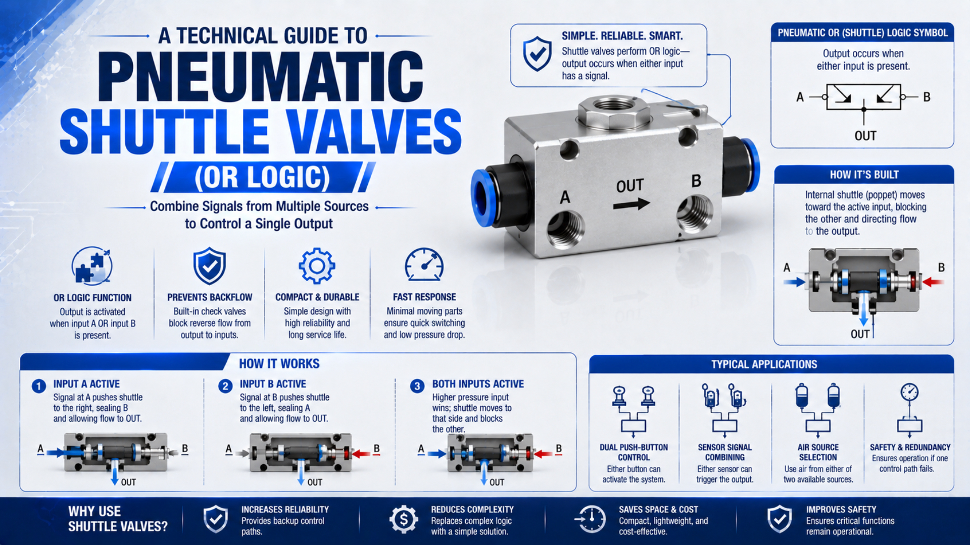
A pneumatic shuttle valve combines two air-signal inputs into one output while isolating the inactive inlet. It implements an OR function without electrical power, but it does not add the two inlet pressures, regulate pressure, or prove a machine safety function.
The simple symbol hides several selection questions. Which inlet wins when both are pressurized? Will the downstream pilot receive enough pressure while air is flowing? What happens if one signal leaks or arrives late? Reliable selection comes from the exact valve data, not from the OR symbol alone.
Key Takeaways
- A shuttle valve passes either valid input and blocks crossflow toward the other inlet.
- Pressure balance, arrival order, minimum differential, and flow capacity are model-specific.
- Standard shuttle valves are not automatically safety-rated components.
- Size from dynamic pressure and manufacturer flow data, not thread size alone.
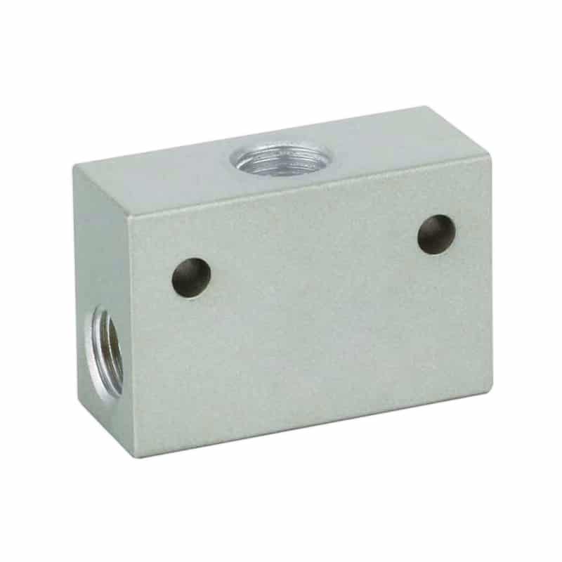
The compact ST Series pneumatic shuttle valve shows the typical physical layout: two inlet ports act on a moving internal element, and a third port carries the selected signal downstream.
What Does a Pneumatic Shuttle Valve Actually Do?
SMC describes its VR1210/1220 shuttle valve as an OR valve: air supplied to either IN port reaches OUT, and the higher-pressure side supplies the outlet when inlet pressures differ. That family is rated from 0.05 to 1.0 MPa and -5°C to 60°C without freezing (SMC VR Series, retrieved 2026).
A pneumatic shuttle valve is a three-port selector with two inlets and one outlet. A ball, poppet, spool, or similar moving element shifts toward one inlet seat. The open side communicates with the outlet while the seated side is isolated. This prevents one control line from simply feeding backward into the other.
The Boolean truth table is straightforward, provided 1 means a valid pneumatic signal rather than any pressure above zero:
| Input A | Input B | Logical output | Physical interpretation |
|---|---|---|---|
| 0 | 0 | 0 | Neither inlet can supply the outlet |
| 1 | 0 | 1 | A supplies OUT; B is isolated |
| 0 | 1 | 1 | B supplies OUT; A is isolated |
| 1 | 1 | 1 | One inlet path is selected according to pressure, timing, and valve construction |
The outlet pressure is not the sum of A and B. It is the pressure available through the selected path after losses in the shuttle valve, tubing, fittings, and upstream signal device. That distinction matters when OUT pilots a larger directional valve or fills a remote control volume.
For the broader relationship between AND, OR, NOT, memory, and timing functions, see the role of pneumatic logic valves in control-system design.
Why Isn’t OR Logic the Same as Guaranteed Priority?
Parker specifies a 3 psig minimum differential for one N164 shuttle-valve family and states that the higher-pressure port is selected when both inlets are pressurized (Parker Automation Valves, retrieved 2026). That is model data, not a universal shuttle-valve threshold.
A standard shuttle valve reacts to force on its internal element. It does not know which source the designer considers primary. If the normal source is 5.8 bar and the backup source is 6.0 bar, the backup may dominate even when both are healthy. If the two pressures are very close, friction, flow forces, leakage, and arrival timing can influence which side remains seated.
This creates four practical limits:
- No fixed source identity: A and B are interchangeable unless another component establishes priority.
- No pressure addition: Two 6 bar inputs do not produce a 12 bar output.
- No guaranteed seamless transfer: Outlet pressure can dip or pulse during a source change.
- No health diagnosis: A valid output can hide a failed or leaking inlet.
The useful engineering distinction is between availability logic and priority logic. A shuttle valve can make OUT available from A or B. It cannot, by itself, guarantee that A is always preferred, that B is used only after an A failure, or that a transfer meets a maximum pressure-dip requirement.
When deterministic source priority matters, compare a shuttle valve with a pressure-sequence arrangement, a controlled directional valve, or monitored electrical logic. The right choice depends on the required transfer state, permissible backflow, switching time, and fault response.
Shuttle-Valve Flow and Pressure Sizing
ISO 6358-1 defines steady-state test methods for pneumatic components using compressible fluids. SMC publishes sonic conductance values of 1.3 and 2.9 dm³/(s·bar) for its VR1210-01 and VR1220-02 models, both with a critical pressure ratio of 0.2 (ISO 6358-1; SMC VR Series).
Port thread is only a connection size. It does not tell you the effective internal passage, pressure loss, or how much flow reaches the downstream pilot. Two 1/4-inch valves can have very different conductance because their seats and moving elements are different.
Start with the downstream requirement:
- Define the minimum pressure that the pilot, clamp, or other load needs while air is flowing.
- Record the minimum available pressure at each inlet, not only the regulator setpoint.
- Estimate peak flow or the required fill time for the downstream volume.
- Allocate pressure loss across the upstream valve, shuttle valve, fittings, tubing, and exhaust path.
- Check both A-to-OUT and B-to-OUT directions against manufacturer data.
| Published parameter | SMC VR1210-01 | SMC VR1220-02 | Selection meaning |
|---|---|---|---|
| Port size | 1/8 | 1/4 | Connection compatibility only |
| Minimum operating pressure | 0.05 MPa | 0.05 MPa | Lowest catalog operating point |
| Maximum operating pressure | 1.0 MPa | 1.0 MPa | Upper component limit |
| Sonic conductance C | 1.3 dm³/(s·bar) | 2.9 dm³/(s·bar) | Compressible-flow comparison |
| Critical pressure ratio b | 0.2 | 0.2 | Used with ISO 6358 flow characterization |
Parker’s N164 family illustrates the same point. Its published Cv values are 0.32 for 1/8 inch, 1.65 for 1/4 inch, and 2.02 for 3/8 inch. Those numbers should not be mixed directly with ISO 6358 conductance without using the correct conversion and test assumptions.
For a deeper treatment of dynamic losses, use the pneumatic valve pressure-drop guide and the engineering guide to flow-control valve sizing. A calculator is a screening aid, not a substitute for the selected model’s compressible-flow data.
Applications That Fit Shuttle-Valve OR Logic
SMC’s VR catalog shows an OR circuit in which activating either input A or B actuates a cylinder. This is the natural use of a shuttle valve: combine two independent pneumatic commands while preventing the active command from feeding backward into the other signal line (SMC VR Series, retrieved 2026).
Good applications share one requirement: either input may legitimately request the same output state.
- Two manual stations can send the same non-safety production command.
- A machine cycle signal or a maintenance jog signal can pilot the same directional valve, provided their interaction is documented.
- Two independent sensors can initiate one reject or blow-off function.
- A normal air signal and a permitted backup signal can feed one pilot when transfer behavior is not safety-critical.
- Separate pneumatic branches can be combined while limiting crossflow between the command lines.
What makes a poor application? Avoid a standard shuttle valve when both commands must be present, when simultaneous inputs must be rejected, when one source must always have fixed priority, or when outlet pressure must be regulated. An AND valve, monitored control system, sequence valve, regulator, or directional valve may match those requirements better.
Don’t use a shuttle valve as a substitute for a check valve in every one-way-flow problem. A check valve has one inlet and one outlet and blocks reverse flow. A shuttle valve has two competing inlets and one selected outlet. The pneumatic check-valve guide explains the difference in cracking pressure, reverse leakage, and load-holding limits.
Write the required output state before choosing the symbol. “OUT when A or B is valid” supports a shuttle valve. “OUT only when A and B agree,” “OUT only from A while A is healthy,” and “safe stop after any single fault” are different control requirements, even if each drawing contains two input lines.
Safety Limits for Shuttle Valves
ISO 13849-1:2023 applies to safety-related control-system parts regardless of whether the technology is electrical, hydraulic, pneumatic, or mechanical. It requires a design and integration methodology for safety functions, but it does not assign the required function or performance level for a particular machine (ISO 13849-1, 2023).
A standard shuttle valve is not automatically an emergency-stop valve, two-hand control device, or safety-rated redundant element. OR logic can even conflict with a stop philosophy: if either signal maintains OUT, one stuck or trapped input may keep the command active after the other input disappears.
ISO 4414 addresses significant hazards associated with pneumatic systems and applies across design, installation, operation, maintenance, and intended use (ISO 4414, 2010). A machine risk assessment must therefore consider more than the component’s normal truth table.
For any safety-related use, define and validate at least:
- the safe state after loss of either inlet, main supply, or electrical power;
- the effect of a stuck shuttle, blocked tube, cross-leak, and residual pressure;
- required diagnostic coverage and fault-detection time;
- restart and reset behavior after pressure returns;
- required performance level and subsystem architecture;
- component reliability data and validation evidence.
If the function is emergency stop, guard interlocking, two-hand control, or prevention of hazardous motion, start with the safety requirements specification. The ISO 13849 pneumatic safety-circuit guide provides the larger validation context.
Installation and Commissioning
SMC specifies 3 to 5 N·m tightening torque for 1/8-inch R or NPT fittings and 8 to 12 N·m for 1/4-inch fittings on the VR1210/1220 series. Its manual also warns against allowing sealant tape or debris into the valve (SMC VR1210/1220 Manual, retrieved 2026).
Those values demonstrate why “tighten securely” is not an installation specification. Use the torque, thread engagement, compatible sealant, tube size, and mounting instructions for the exact model. Another manufacturer’s body material or port design may require a different method.
Follow this commissioning sequence:
- Isolate and dissipate pneumatic energy using the machine’s approved procedure.
- Identify both IN ports and the OUT port from the valve marking or drawing.
- Flush or clean new tubing before connecting it.
- Keep cut tape, liquid sealant, chips, and tube fragments out of the ports.
- Support piping so the valve body does not carry alignment or bending load.
- Pressurize A alone and verify OUT while checking that B does not receive backflow.
- Repeat the test with B alone.
- Pressurize both inputs at minimum expected operating pressure and record the outlet response.
- Remove each signal separately and confirm the required reset or transfer behavior.
- Repeat the functional test at the machine’s highest simultaneous air demand.
Mounting orientation must also come from the selected documentation. Ball, poppet, and spool constructions do not all respond to gravity and vibration in the same way. A blanket instruction to install every shuttle valve horizontally or never invert one is not defensible.
The manual and mechanical valve selection guide can help define the upstream signal devices that feed A and B.
Diagnosing Erratic Shuttle-Valve Behavior
SMC states that a pressure difference of 0.05 MPa or more makes the higher-pressure inlet continuously feed OUT for its VR1210/1220 family. If an installed valve chatters or changes source unexpectedly near balanced pressure, compare the measured differential with the selected model’s specification before replacing parts (SMC VR Series, retrieved 2026).
Measure pressure at all three ports during the fault. Static regulator gauges can miss the transient dip created when a pilot valve opens or a long tube fills.
| Symptom | Possible shuttle-valve cause | Other causes to exclude | Useful check |
|---|---|---|---|
| No output from A | Wrong port, blocked passage, stuck element | Closed upstream valve, low A pressure, tube kink | Pressurize A alone and measure A plus OUT |
| A works but B does not | Contamination or damaged B seat/path | Incorrect B signal valve, fitting restriction | Swap controlled test inputs if permitted |
| Outlet pressure is low under flow | Undersized conductance or contamination | Small tubing, low supply, restricted upstream valve | Record A/B and OUT pressure during demand |
| Source chatters between A and B | Marginal differential or unstable pressure | Regulator hunting, compressor pulsation, vibration | Trend both inlet pressures simultaneously |
| Air appears at inactive inlet | Seat leakage, debris, damaged element | Incorrect tubing or external cross-connection | Isolate branches and perform a defined leakage test |
| Command remains after one input vents | Other inlet still valid or trapped pressure | Blocked exhaust, leaking signal valve, downstream memory | Measure all ports during reset |
Treat “wrong inlet selected” as a three-pressure problem, not a valve-only diagnosis. A valve can be functioning as designed while the real fault is a dynamic supply drop on the intended source. Recording A, B, and OUT on the same time base separates source instability from internal switching trouble.
Never disconnect a pressurized tube to identify the live inlet. Use rated test points, guarded equipment, and the approved energy-control procedure.
A Complete Shuttle-Valve RFQ
Parker lists three N164 models with 1/8-, 1/4-, and 3/8-inch ports, Cv values from 0.32 to 2.02, a 200 psig maximum operating pressure, and a 3 psig minimum differential. A useful RFQ must therefore identify the required operating point, not merely request “one OR valve” (Parker Automation Valves, retrieved 2026).
Send the supplier these details:
- pneumatic schematic with A, B, and OUT identified;
- normal, minimum, and maximum pressure at each inlet;
- expected pressure difference when both inlets are active;
- required downstream pilot pressure and peak flow;
- allowed pressure drop or maximum downstream fill time;
- port thread standard and tube size;
- air quality, lubrication policy, condensate, and contamination conditions;
- ambient and fluid temperature range;
- body and seal compatibility requirements;
- mounting orientation, vibration, washdown, and space limits;
- acceptable leakage between each inlet and the inactive branch;
- required switching, reset, endurance, and fault-state tests;
- any safety-related function and the evidence required by the machine design.
Ask for the flow curve or ISO 6358 characteristics in both inlet-to-outlet paths. Also request the test conditions behind any response-time or leakage figure. A number without upstream pressure, downstream pressure, temperature, and acceptance criteria is difficult to use in a design review.
Pneumatic Shuttle Valve FAQs
SMC and Parker publish different minimum pressure and differential values for their shuttle-valve families. That variation is the central answer to most buyer questions: the OR symbol defines the logical function, while the selected manufacturer’s data defines pressure, flow, switching, leakage, temperature, and installation limits.
Does a shuttle valve add pressure from both inlets?
No. A shuttle valve selects an inlet path and connects it to the outlet while isolating the other inlet. Two 6 bar signals do not create a 12 bar output. Actual OUT pressure is the selected inlet pressure minus dynamic losses through the signal valve, shuttle element, fittings, and tubing.
What happens when both shuttle-valve inputs have equal pressure?
Do not assume both inlets remain open or that the moving element stays perfectly centered. Near equal pressure, the selected path can depend on arrival order, internal friction, flow forces, leakage, and construction. Use the manufacturer’s switching specification and test the real circuit at its minimum differential.
What minimum pressure differential does a shuttle valve need?
It depends on the model. Parker specifies a 3 psig minimum differential for one N164 family. SMC states that a 0.05 MPa or greater difference keeps the higher-pressure side feeding OUT in its VR1210/1220 family. Neither figure should be applied to an unrelated valve without documentation.
Can a shuttle valve be used in an emergency-stop circuit?
Not as an automatically accepted safety solution. A standard shuttle valve provides OR logic but does not establish the required safe state, performance level, diagnostics, reset behavior, or fault tolerance. Safety-related pneumatic controls require a machine risk assessment, specified architecture, suitable component data, and validation under the applicable standards.
How should a shuttle valve be sized?
Start with the downstream pilot pressure, peak flow, minimum inlet pressure, allowed pressure loss, and required fill time. Then compare manufacturer Cv or ISO 6358 flow characteristics for both inlet paths. Confirm pressure range, temperature, port standard, material compatibility, leakage, and switching differential before approving the exact part number.
Sources
- ISO 4414:2010, Pneumatic fluid power general rules and safety requirements
- ISO 6358-1:2013, Steady-state pneumatic flow-rate characteristics
- ISO 13849-1:2023, Safety-related parts of control systems
- SMC VR Series shuttle-valve catalog
- SMC VR1210/1220 operation manual
- Parker N164 shuttle-valve catalog