

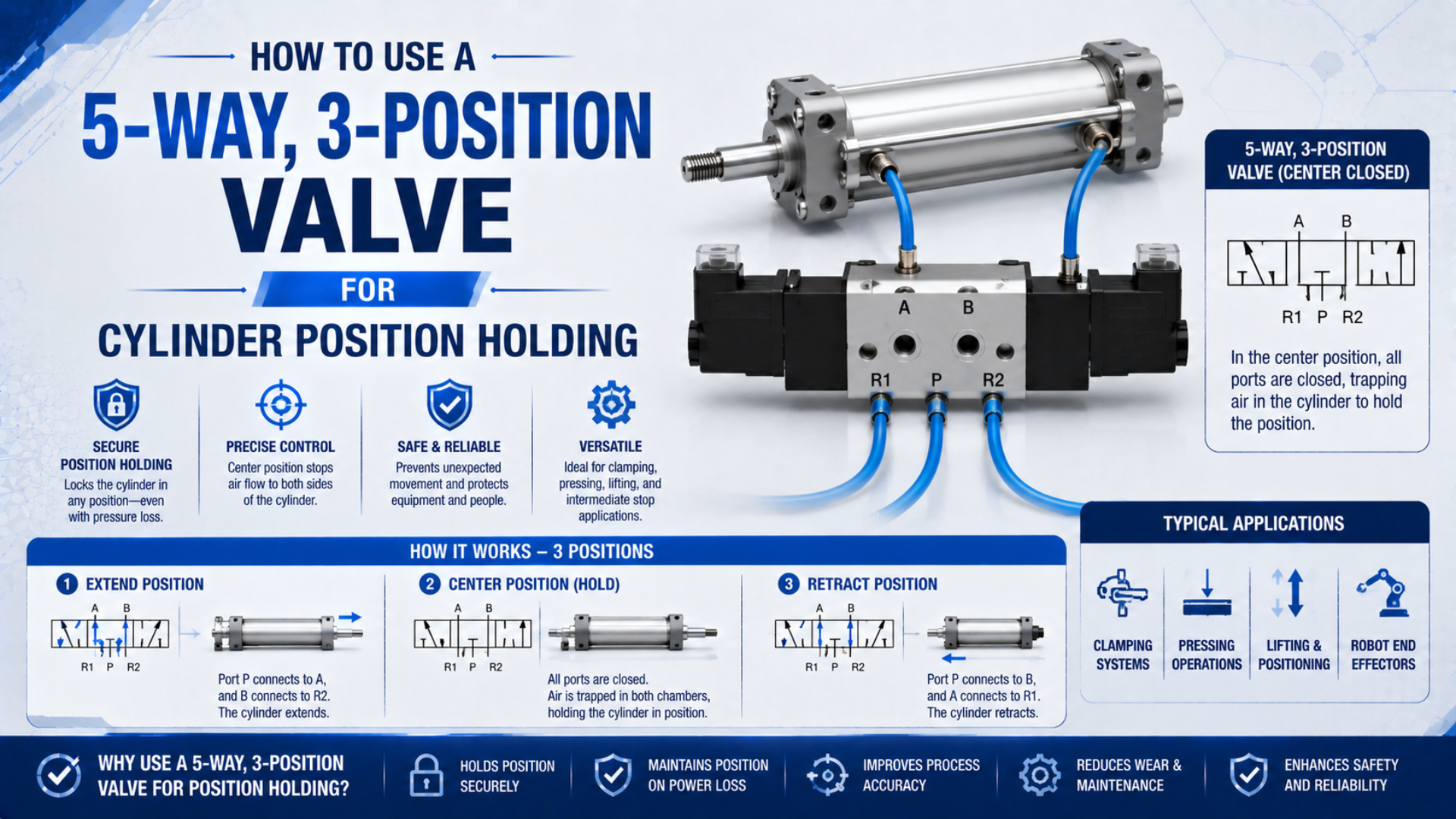
With a closed center, a 5-way, 3-position valve can pause a double-acting cylinder by blocking its supply, two working ports, and two exhaust ports. It cannot promise zero drift, indefinite pressure retention, or safe load holding. SMC warns that accurate intermediate stopping is difficult because air compresses and pneumatic components aren’t guaranteed to have zero leakage (SMC VQ100 guidance, accessed 2026).
Use the closed-center state for a controlled production pause only after testing the real load, orientation, leakage, temperature, tubing volume, and restart behavior. If movement could injure someone or drop a vertical load, add a purpose-designed holding device and apply the machine’s energy-control procedure.
Key Takeaways
- A 5/3 valve has five ports and three spool positions; closed center blocks all five in neutral.
- Trapped air can leak and compress, so the cylinder may creep or rebound.
- Use pilot-operated checks for stronger pneumatic holding and a mechanical lock when motion creates a hazard.
How Does a 5-Way, 3-Position Valve Pause a Cylinder?
A 5/3 directional valve has five ports and three spool positions. Festo explains that it uses the same five-port layout as a 5/2 valve, with one additional intermediate position (Festo pneumatic valve guide, accessed 2026). Cylinder holding depends on what that third position connects or blocks.
A 5/3 directional valve is a five-port valve with two powered flow states and one intermediate spool state. Closed center is only one possible intermediate function. Other 5/3 variants can pressurize both working ports or connect them to exhaust, so the full symbol belongs on the machine drawing and RFQ.
Port functions are normally identified as follows:
| Port | Common label | Function |
|---|---|---|
| 1 | P | Compressed-air supply |
| 2 | B | Working connection to one cylinder chamber |
| 3 | EB, R, or R2 | Exhaust for one flow path |
| 4 | A | Working connection to the opposite cylinder chamber |
| 5 | EA, S, or R1 | Exhaust for the other flow path |
Port numbering and letter conventions vary by manufacturer, so follow the symbol printed on the valve or manifold. Don’t infer the spool function from the body shape or connector count. For the two powered positions, the related guide to 4-way, 5-port valve routing explains each path in more detail.
With solenoid 14 energized, a typical spool connects P to A while B exhausts. With solenoid 12 energized, P connects to B while A exhausts. When both commands turn off, centering springs return the spool to its third position. A closed-center version blocks P, A, B, EA, and EB at that moment.
Electrical design must account for the center condition too. A spring-centered, double-solenoid valve normally returns to neutral when both coils are off, but coil overlap, a stuck spool, a manual override, pilot-pressure loss, or conflicting PLC outputs can produce a different result. Verify the specific valve’s de-energized state rather than relying on the phrase “5/3 valve.”
Why Doesn’t a Closed-Center Valve Guarantee Zero Drift?
SMC identifies two reasons a 3-position closed-center circuit cannot guarantee an exact stop: compressed air is compliant, and valves plus cylinders aren’t guaranteed to have zero leakage (SMC VQ100 guidance, accessed 2026). Blocking five ports stops commanded flow, not every possible pressure change.
Closed-center position holding means the directional valve blocks its ports while the cylinder remains supported by trapped pneumatic pressure. It is not a positive mechanical restraint. The distinction matters whenever engineers write a safe-state description, because “valve centered” and “moving member physically secured” are different verifiable conditions.
The trapped volume includes both cylinder chambers, both hoses, fittings, sensor adapters, and internal valve passages. Longer tubing creates a larger air spring. When the load changes, that air compresses or expands before the pressure forces find a new balance. Even with a perfectly centered spool, the carriage can move. Leakage provides a slower path to the same result. Air can pass across the spool, piston seal, rod seal, tube fitting, or accessory. Festo’s safety guidance says a stopped cylinder can move according to the leakage of individual components and warns designers to consider this behavior during restart (Festo Safety Engineering Guidelines, p. 48, accessed 2026). Isolating each volume and logging chamber pressure beside actual position makes the decay path measurable.
Temperature also matters. Air trapped beside a warm process, washdown zone, oven, or sunlit enclosure changes pressure as its absolute temperature changes. If the two chamber volumes or temperatures differ, the resulting pressure change isn’t symmetrical. Relief and safe exhaust provisions must be engineered for the selected circuit, not added as arbitrary percentages above working pressure. Finally, the piston may not have equal effective area on both sides. A single-rod cylinder has full piston area on the cap side and an annular area on the rod side. Equal chamber pressures therefore don’t imply equal forces. That point is easy to miss when a schematic shows two blocked lines. The imbalance can bias a lightly loaded rod before an external leak becomes obvious.
Force Balance Inside a Trapped Cylinder
A single-rod cylinder has two effective areas. Festo Didactic defines the rod-side annular area as full piston area minus rod area, so equal chamber pressure doesn’t create equal opposing forces (Festo Didactic, accessed 2026). The remaining pressure force equals pressure multiplied by rod area.
Ignoring acceleration, the pressure contribution to axial force is:
The two effective areas are:
Here, and are absolute or gauge chamber pressures expressed on the same basis, is full piston area, is rod-side annular area, is bore diameter, and is rod diameter. Subtract the external load and friction in the correct direction to determine the static net force.
Consider a 63 mm bore cylinder with a 25 mm rod. If both chambers are momentarily at 6 bar gauge, the pressure imbalance alone is about toward extension, before load and friction are included. This is an illustrative geometry calculation, not a permissible holding-load rating.
The number also changes as soon as the piston moves because each chamber volume changes. A small displacement compresses one side and expands the other, creating an air-spring response. Seal friction may hide that movement at first, then release as stick-slip. That’s why acceptance testing must measure position over the full dwell, not only at the instant the valve enters neutral. For an initial load-side check, the Pneumatic Cylinder Force Calculator can estimate push and pull force separately. It cannot predict long-term trapped-pressure decay. Use measured leakage, actual tube volume, load direction, and the manufacturer’s holding-device specifications for that decision.
When Is Closed-Center Position Holding Appropriate?
SMC warns that a 3-position closed-center valve cannot assure an accurate intermediate stop or extended hold, but that doesn’t make the center state useless (SMC VQ100 guidance, accessed 2026). It is appropriate when a tested amount of temporary movement is acceptable and no hazardous load depends on trapped air.
Good candidates usually share these conditions:
- The axis cannot drop a suspended load.
- Short, defined production pause.
- Measured movement remains inside a documented product and tooling tolerance under the worst expected load.
- Position sensors confirm the axis remains inside its accepted window before any tool, conveyor, or downstream station is permitted to continue automatic motion.
- Restart logic accounts for pressure imbalance and possible jump motion.
- The machine remains guarded while pneumatic energy is trapped.
A packaging guide that pauses for a product check may fit this category if the measured drift stays inside the process window. A lift, clamp over an operator, suspended fixture, or axis used as a maintenance support does not. The difference is consequence, not merely cylinder bore or valve size.
Define an acceptance test before selecting the valve. Record the starting position, chamber pressures, supply state, load, orientation, temperature, and dwell time. Then measure maximum displacement during the dwell and the first movement after re-energization. Repeat with the minimum and maximum expected load, not only an unloaded cylinder on a bench. Avoid calling this “precise positioning.” A discrete 5/3 valve commands three pneumatic states, not a measured coordinate. If the machine must move to several repeatable intermediate setpoints, use mechanical stops, a multi-position actuator, or a closed-loop proportional positioning system with continuous feedback.
Which Holding Method Fits the Risk and Dwell Time?
Parker describes a dual pilot-operated check module made from two normally closed 3/2 paths and states that mounting it close to the cylinder provides more accurate positioning than a 3-position closed-center valve (Parker Moduflex Valve System, accessed 2026). Even that pneumatic hold isn’t automatically a mechanical safety lock.
A pilot-operated check valve is a normally closed blocking element that permits free flow in one direction and requires pilot pressure to release reverse flow. Its cracking pressure, pilot ratio, rated flow, reverse leakage, and installation location all affect performance. The pilot-operated check valve engineering guide covers those selection variables separately.
| Method | What it controls | Suitable use | Main limitation |
|---|---|---|---|
| 5/3 closed-center valve | Blocks supply and both working ports at the directional valve | Short, nonhazardous production pause | Hose, fitting, valve, and cylinder leakage remain in the trapped volume |
| Dual pilot-operated checks | Blocks each cylinder line near the actuator | Longer pneumatic hold or reduced line-side leakage | Air remains compressible; cylinder seals and fittings can still leak |
| Rod lock or mechanical brake | Physically restrains the rod or moving member | Vertical loads and applications where unintended motion is hazardous | Requires correct holding-force rating, release logic, alignment, and proof testing |
| Mechanical stop or pin | Creates a positive physical support | Maintenance support or fixed indexed positions | Must be engaged, verified, and rated for the load |
| Proportional valve with feedback | Continuously corrects measured position error | Multiple commanded positions and controlled motion | Needs sensor, controller, tuning, fault handling, and a separate safety strategy |
Mounting a check device near the cylinder shortens the volume and reduces the number of fittings between the blocking element and actuator. It doesn’t eliminate piston-seal leakage or air compliance. SMC’s double-check guidance also warns that leakage from the piping, fittings, tube gasket, piston packing, or rod packing can prevent a long hold (SMC VQZ catalog, accessed 2026). For gravity-loaded axes, read the cylinder rod-lock safety guide before treating trapped pressure as the final barrier. A rod lock still needs a verified rating, release pressure, control sequence, alignment, and maintenance test. It complements risk reduction; it doesn’t replace guarding or lockout/tagout.
Circuit Commissioning and Acceptance Tests
One Festo ISO 5599-1 valve family lists 18 ms on, 55 ms off, and 32 ms changeover for a specific 5/3 closed-center configuration (Festo valve documentation, accessed 2026). Those values show why commissioning must use the selected model’s data instead of a universal response-time range.
Start with the schematic and bill of materials. Confirm the exact center symbol, pilot arrangement, coil voltage, connector, manual override, exhaust configuration, pressure range, flow data, and permitted mounting orientation. A dual-solenoid body isn’t proof of a closed-center spool. The ordering code and manufacturer symbol are the controlling evidence.
Next, verify the air path:
- Connect P, A, B, EA, and EB according to the valve symbol.
- Install meter-out flow controls only where they won’t prevent a holding accessory from piloting or exhausting correctly.
- Keep any pilot-operated check close to the cylinder and minimize trapped-line fittings.
- Confirm mufflers and exhaust manifolds won’t create unexpected back pressure.
- Set supply pressure and air quality within the selected valve, cylinder, and accessory specifications.
Valve flow still determines normal stroke performance. Size the working and exhaust paths from bore, stroke, target time, load, supply pressure, tubing length, and acceptable pressure drop. The Cv sizing guide helps compare valve restrictions, while the cylinder flow requirement calculator estimates the flow demanded by a target stroke time. Then test the controls at reduced energy. Command each powered position separately, confirm motion direction, and verify that removing both commands produces the intended neutral state. Check the PLC for output overlap and confirm the spool centers after loss of electrical power and after loss of pilot pressure. The correct solenoid-valve control sequence must be proven at the actuator, not inferred from indicator LEDs. Record actual stroke time in both directions.
Finish with a recorded holding test. Use calibrated position and pressure measurements if the result matters to process acceptance. Test minimum and maximum load, both motion directions, expected temperature range, supply isolation, maximum dwell, vibration, and restart. State the allowable movement in millimeters and the allowable restart transient. “No visible drift” isn’t a measurable acceptance criterion.
The restart test deserves equal weight with the dwell test. One chamber may lose more pressure than the other while stopped. When the spool reconnects supply and exhaust, the stored imbalance can create a jump before normal speed control takes over. Require position confirmation and a controlled recovery state before the machine resumes automatic production.
What Causes Drift, Rebound, or Unexpected Restart Motion?
SMC names at least five leakage locations in a long-hold circuit: piping, fittings, the cylinder tube gasket, piston packing, and rod packing (SMC VQZ catalog, accessed 2026). Troubleshooting should isolate these paths instead of assuming the directional spool is the only source of movement.
| Symptom | Likely mechanism | Diagnostic check | Corrective direction |
|---|---|---|---|
| Slow drift in one direction | Unequal leakage or sustained external load | Log both chamber pressures and position through the full dwell | Isolate valve, tubing, fittings, and cylinder leakage separately |
| Immediate movement after centering | Spool didn’t reach neutral, command overlap, or air compliance | Monitor both coil outputs and pressure at A and B | Correct logic, pilot supply, spool selection, or mechanical load balance |
| Rebound after a fast stop | Compressed air and moving mass exchange energy | Compare stop distance at several speeds and loads | Reduce approach speed, add cushioning, or change the stopping method |
| Jump on restart | Chamber pressure decayed unevenly during the hold | Record pressure immediately before and after re-energization | Add a controlled pressure-equalization and restart sequence |
| Position changes with temperature | Trapped-air temperature or external process heat changed | Trend chamber pressure and temperature together | Reduce trapped volume and engineer relief or isolation for the real thermal case |
| Axis drops after supply loss | Trapped pressure escaped or no positive mechanical restraint exists | Test the defined fault under controlled, guarded conditions | Add a rated rod lock, brake, stop, or other risk-assessed holding measure |
Don’t search for a universal leak-free valve. Manufacturer catalogs define allowable leakage and application limits for particular products, and fittings may introduce their own leakage. A better troubleshooting boundary is to divide the circuit at the valve and cylinder ports, measure pressure decay on each isolated volume, and compare the result with the process tolerance. Maintenance intervals should also come from component instructions, cycle count, contamination, observed leakage, and the machine’s risk assessment. A fixed weekly, monthly, or annual schedule can’t be justified for every valve family. After any seal, fitting, valve, cylinder, or software change, repeat the holding and restart acceptance tests because the circuit boundary has changed.
Cylinder Position-Holding FAQs
OSHA 1910.147 requires stored or residual energy, including air pressure, to be dissipated or restrained before covered maintenance. That requirement separates production position holding from hazardous-energy isolation: a valve’s third position can pause motion, but it doesn’t by itself make a machine safe to enter or service (OSHA, accessed 2026).
Can a 5/3 closed-center valve hold a cylinder indefinitely?
No. It can trap air temporarily, but valve, fitting, tubing, and cylinder leakage can change chamber pressure over time. SMC specifically warns that closed-center valves and cylinders aren’t guaranteed to have zero leakage. Define a tested dwell time and allowable movement instead of claiming indefinite or zero-drift holding.
Will a closed-center valve prevent a vertical cylinder from dropping?
It may delay movement, but it shouldn’t be the sole safety measure for a hazardous suspended load. Loss of pressure, seal leakage, tube failure, or spool faults can release the load. Use a risk-assessed mechanical rod lock, brake, stop, blocking device, or equivalent measure with verified holding capacity.
Is a dual pilot-operated check valve better for position holding?
It usually reduces leakage through the directional valve and works best close to the cylinder. Parker describes this arrangement as more accurate than a standard 3-position closed-center valve. It still traps compressible air and cannot eliminate leakage across cylinder seals, fittings, or the check devices themselves.
Does a 5/3 valve provide several programmable cylinder positions?
No. Its third spool position defines a neutral flow state, not a coordinate. Repeatable programmable positions require feedback plus proportional or servo control, or discrete mechanical stops and multi-position hardware. A sensor should confirm the actual actuator position because the valve command only reports the requested pneumatic state.
What should be included in the holding acceptance test?
Record load, orientation, supply state, both chamber pressures, initial position, temperature, dwell time, maximum displacement, and restart motion. Repeat the test at minimum and maximum expected load. If unintended movement could cause harm, validate the independent mechanical restraint and the machine’s energy-control procedure separately.
Sources and technical references
SMC: VQ100 Clean Series application cautions, intermediate stops, leakage, pressure holding, and residual-pressure release. Retrieved 2026-07-22.
Festo Didactic: Mechatronics Pneumatics, piston area, rod-side annular area, and cylinder-force fundamentals. Retrieved 2026-07-22.
Festo: Pneumatic Valves Guide, 5/2 and 5/3 valve definitions and center-position behavior. Retrieved 2026-07-22.
Festo: Safety Engineering Guidelines, page 48, stopping with non-return valves, stored air, leakage, and restart cautions. Retrieved 2026-07-22.
Festo: Standards-Based Valves to ISO 5599-1, model-specific 5/3 center functions, flow data, and switching times. Retrieved 2026-07-22.
Parker: Moduflex Valve System, dual pilot-operated check module and cylinder-positioning guidance. Retrieved 2026-07-22.
SMC: VQZ1000/2000/3000 Catalog, double-check blocks, leakage paths, piping cautions, and product-specific limits. Retrieved 2026-07-22.
OSHA: 1910.147 Appendix A, control of hazardous and residual energy during servicing. Retrieved 2026-07-22.
OSHA: Energy Control and Control Circuitry Prohibition, physical isolation, residual pressure, bleed valves, and verification. Retrieved 2026-07-22.