

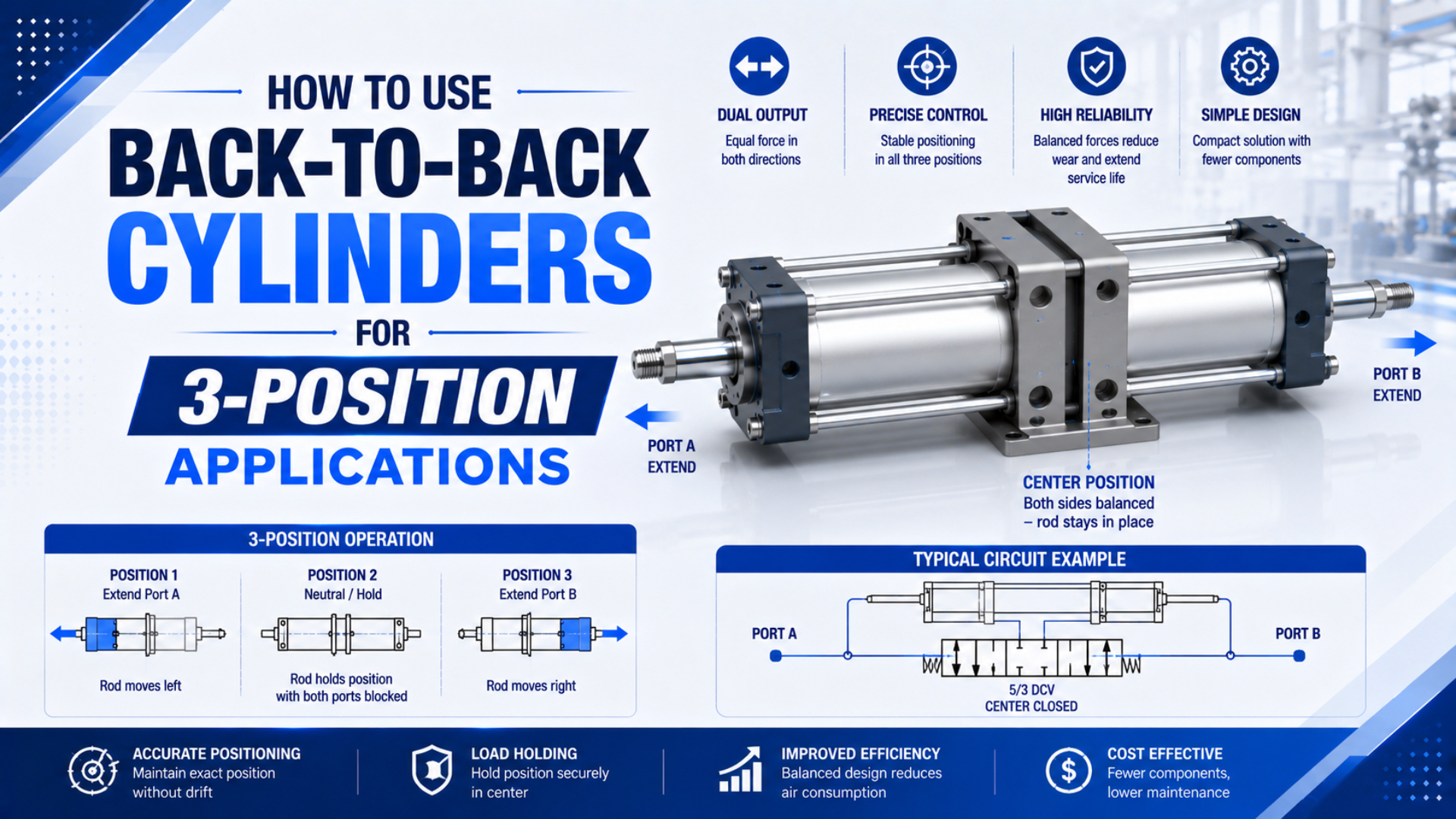
Back-to-back cylinders create three repeatable positions by combining two fixed strokes, not by balancing two air pressures at a floating midpoint. With equal strokes, four valve-command states collapse into three mechanical locations: both stages retracted, either one extended, and both extended. Reliable operation then depends on mounting, sequencing, force, flow, and fault handling.
This guide focuses on the practical equal-stroke arrangement. For a broader comparison of equal-stroke, unequal-stroke, and integrated designs, see our multi-position cylinder architecture guide.
Key Takeaways
- Equal strokes produce three unique locations from four command states because two states share the same total travel.
- Mechanical end stops define the positions; trapped or balanced air does not provide an equally rigid stop.
- Each double-acting cylinder normally needs independent directional control or an equivalent manufacturer-approved circuit.
- Size force, flow, cushioning, guidance, sensors, and fault response for every transition, not only the final position.
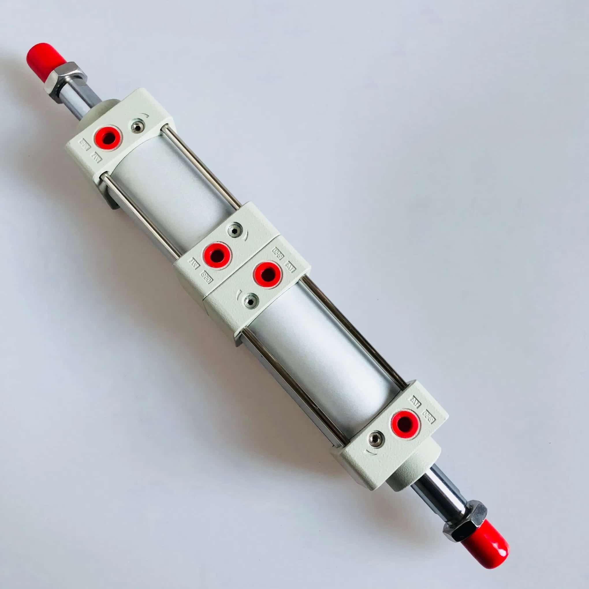
How Do Equal-Stroke Back-to-Back Cylinders Create Three Positions?
Festo describes a multi-position arrangement as two separate cylinders whose piston rods advance in opposite directions. Its product guidance states that equal strokes provide three positions, while different strokes provide four (Festo Multi-Position Cylinders, accessed July 22, 2026).
Let cylinder A have stroke and cylinder B have stroke . If and are command states that equal 0 when retracted and 1 when extended, total travel is:
Here, is the resulting actuator position measured from the home reference, and are the two mechanical strokes, and and indicate which stroke has been added. This kinematic model assumes the cylinders and load reach their specified end stops without structural deflection or incomplete travel.
For equal strokes, , so the possible positions are:
| Cylinder A | Cylinder B | Calculated travel | Unique machine position |
|---|---|---|---|
| Retracted | Retracted | 0 | Home |
| Extended | Retracted | S | Intermediate |
| Retracted | Extended | S | Intermediate |
| Extended | Extended | 2S | Full travel |
The two middle command combinations reach the same nominal coordinate. They are not always operationally interchangeable, however. Different moving masses, hose routing, cushions, or tooling clearance can make one transition preferable. Define the permitted path in the PLC instead of assuming either middle-state command is safe.
A back-to-back three-position arrangement is a two-cylinder assembly in which the strokes add along one motion axis. Festo’s current guidance identifies three unique positions when the two strokes are equal and four when they differ. Parker documents the equal-stroke sequence as both rods retracted, one rod extended, and both rods extended. Together, those sources establish the engineering boundary: the intermediate coordinate comes from one completed mechanical stroke, not from an unsupported claim about equal pressure. They also explain why the four electrical command combinations must stay visible in the control logic even though the machine has only three nominal coordinates. Stroke tolerances, stop compliance, mounting deflection, guide clearance, load direction, speed, and direction of approach still determine the measured result (Festo; Parker C41, accessed July 22, 2026).
[UNIQUE INSIGHT] The intermediate coordinate has two possible command histories even though it has only one nominal location. Treat “A extended” and “B extended” as separate machine states in diagnostics. That distinction makes valve, sensor, or cushion faults much easier to isolate.
What Must Move and What Must Stay Fixed in the Mechanical Layout?
A back-to-back assembly is not two stationary cylinders pushing against each other. At least one cylinder body or connected assembly must be free to translate as the strokes combine. Festo explicitly notes that one cylinder must move when the other is driven and therefore requires flexible tubing connections in that arrangement.
Start the design with a motion sketch that labels:
- the machine-fixed mounting point;
- each cylinder body and piston rod;
- the member that translates when cylinder A changes state;
- the member that translates when cylinder B changes state;
- the load connection, guide rails, hard stops, hoses, and cable loops;
- the total envelope at 0, S, and 2S travel.
Parker’s multi-position examples connect the rear end covers with flanges and require the cylinders to move lengthwise. Follow the selected manufacturer’s mounting drawing instead of improvising a rigid rod-to-rod connection. Mount reactions, allowed moments, rod-end articulation, and available accessories differ by series.
The cylinder assembly should drive the load; it should not be the machine’s precision guide. An external linear guide is normally needed when the load introduces side force, moment, or an offset center of gravity. The side-loading guide explains how misalignment transfers load into the rod bearing and seals.
Check hose motion throughout the complete envelope. A tube that appears relaxed at the middle position may become taut or kinked at an end position. Provide bend radius, abrasion protection, strain relief, and clearance from pinch points. If a valve manifold moves with a cylinder body, include its mass in the moving-load and stopping-energy calculation.
Which Valve Arrangement Should Control the Two Cylinders?
There is no universal rule that one 5/3 center-pressure valve creates the three positions. The positions come from two mechanical strokes. A common implementation gives each double-acting cylinder an independent 5/2 directional-control function, or uses an equivalent valve arrangement approved for the exact actuator and required fault response.
The control design must answer four separate questions:
- Which chamber of cylinder A is supplied and which is exhausted?
- Which chamber of cylinder B is supplied and which is exhausted?
- Which state transitions may occur directly under load?
- What happens after electrical power or compressed air is lost?
Use the manufacturer’s circuit when selecting an integrated multi-position product. For example, SMC’s RZQ is a dedicated three-position cylinder with model-specific circuit, regulator, overrun, and power-failure guidance; its circuit should not be copied as a generic rule for two arbitrary back-to-back cylinders (SMC RZQ Three-Position Cylinder, accessed July 22, 2026).
Independent directional control means that the advancing and retracting chambers of cylinder A can be commanded without using cylinder B’s valve state as a substitute. Parker’s back-to-back P1D guidance permits equal or different strokes, while SMC’s integrated RZQ publishes its own circuit and failure sequences. Neither source supports a universal “one 5/3 valve” rule for every two-cylinder assembly. The circuit designer must instead map four cylinder states, each permitted transition, the pressure and exhaust path during switching, and the machine response to pilot, electrical, or air-supply loss. Two 5/2 functions are a common starting architecture for two double-acting cylinders, but valve type alone does not prove a safe center state. The selected product documentation, measured flow and pressure, and machine risk assessment must agree before the sequence is released (Parker P1D; SMC RZQ, accessed July 22, 2026).
A practical PLC state table should include more than the two output bits:
| Requested position | Cylinder A command | Cylinder B command | Required confirmation |
|---|---|---|---|
| Home | Retract | Retract | home sensors true within timeout |
| Intermediate via A | Extend | Retract | A-extended and B-retracted confirmation |
| Intermediate via B | Retract | Extend | A-retracted and B-extended confirmation |
| Full travel | Extend | Extend | both extended confirmations true |
Define whether the machine may switch both cylinders simultaneously. Moving one stage at a time often makes the transition easier to diagnose and can limit peak supply demand, but it is not automatically the safest sequence. Tooling interference, gravity, load direction, and the selected valve’s transient behavior determine the acceptable path.
Pressure trapped by a closed-center valve can decay through valve, fitting, tube, or seal leakage. It also stores energy that must be addressed during isolation and maintenance. Do not claim that a pneumatic center state is a positive personnel-safety hold. ISO 4414 covers hazards and safety requirements for pneumatic systems; the machine risk assessment must define safe stop, isolation, dissipation, and load restraint (ISO 4414:2010, confirmed 2021).
How Should Force Be Sized at Each Position and Transition?
Size each cylinder from the force it must deliver in its actual transition. Back-to-back positioning does not automatically double useful force; that is a different function from a tandem cylinder that adds piston forces on a common rod.
For a conventional double-acting cylinder, the full piston area and rod-side annular area are:
Here, is full piston area, is annular area, is bore diameter, and is rod diameter. Use dimensions in consistent units.
For an extension-direction force balance, a useful first-principles expression is:
In this equation, is force available to accelerate or drive the load, is actual cap-end pressure, is opposing rod-end pressure, and includes seal friction, guide friction, gravity, process force, and other opposing loads. Reverse the signs and use the appropriate effective areas when analyzing retraction.
Dynamic cylinder force is the pressure-area force remaining at the load while the actuator is moving, after opposing chamber pressure and application resistance are accounted for. Parker’s engineering method starts with pressure multiplied by effective piston area; a double-acting cylinder therefore requires the full bore area for one side and the smaller annular area for the rod side. In a back-to-back machine, calculate cylinder A and cylinder B separately for each allowed transition because either unit may move the other cylinder body, tubing, manifold, tooling, and process load. Use pressure measured near the ports, not only the upstream regulator setting. Then compare the result with the exact model’s rated force, load ratio, mounting capacity, and allowed side load. A three-position geometry does not add the two forces in the same way as a common-rod tandem actuator (Parker Pneumatic Application Engineering Data, accessed July 22, 2026).
Measure dynamic pressure near the cylinder ports during the most demanding move. A regulator setting does not reveal supply loss through the valve and tubing or back pressure at the restricted exhaust. Also check the weakest state: one cylinder may have to move the mass of the other cylinder, its hoses, and the tooling while working on its smaller annular area.
The result is a sizing screen, not proof of safe capacity. Confirm the exact model’s catalog forces, load ratio, mounting limits, allowable side load, temperature range, and pressure range.
How Should Speed, Flow, and End-of-Stroke Energy Be Controlled?
Each cylinder changes both the moving mass and the volume that must fill or exhaust. Select valves, tubing, fittings, and silencers from the required stroke time and allowable pressure drop, not from port thread alone. A circuit that eventually reaches all three stops can still fail its cycle-time requirement or hit the stops too hard.
Meter-out flow control is commonly used for stable pneumatic-cylinder speed when the load does not overrun, but the correct method remains application- and manufacturer-specific. Install controls in the intended flow direction, begin commissioning at low speed, and adjust one motion at a time. Keep exhaust restrictions visible in the force analysis because back pressure subtracts from available thrust.
Internal cushions are energy absorbers, not position-adjustment screws. Compare moving mass and velocity with the exact model’s permitted kinetic energy. Add an external stop or shock absorber when the cylinder cushion cannot absorb the load. The cylinder cushioning failure guide covers symptoms such as end-cap impact, rebound, and heat.
Use the Cylinder Flow Requirement Calculator to estimate the flow needed for the target stroke time. If stopping energy is the limiting condition, check it separately with the Pneumatic Cylinder Cushion Energy Calculator. Do not use a lower speed setting as a substitute for an undersized mechanical stop or an unsafe load path.
How Do Sensors and PLC Logic Confirm the Three Positions?
State confirmation is evidence that the commanded cylinder combination reached its expected sensing zones within the allowed time. Cylinder switches do not create the mechanical position. The cylinder end stop, external stop, mounting stack, load deflection, and approach direction determine the final coordinate. Use sensors to verify state and detect incomplete motion.
For the equal-stroke arrangement, retain four logical cylinder states even though only three coordinates exist. A useful diagnostic code records:
- A retracted and B retracted;
- A extended and B retracted;
- A retracted and B extended;
- A extended and B extended;
- invalid or contradictory sensor combinations.
Program a transition timeout for each permitted move. If the expected sensors do not change in time, stop the sequence and preserve the commanded state, confirmed state, pressure status, and fault timestamp for troubleshooting. Avoid bypass logic that accepts “one of two middle-state sensors” without recording which cylinder actually moved.
Sensor mounting also needs an acceptance window. Confirm switching at minimum and maximum operating pressure, both directions of approach, the full production speed, and the allowed supply-voltage range. If the machine needs continuous position measurement rather than end-state confirmation, specify a compatible analog sensor, encoder, or position-feedback actuator.
What Commissioning Tests Prove the System Works?
Commission the complete machine under realistic load, pressure, speed, hose routing, and temperature. Catalog strokes explain the nominal geometry; they do not prove the assembled machine’s repeatability, settling time, or fault behavior.
Use a written test matrix:
| Test | Method | Acceptance evidence |
|---|---|---|
| Three coordinates | measure 0, S, and 2S from a fixed machine datum | actual values within the machine drawing tolerance |
| Intermediate-state paths | approach S through A-only and B-only commands | both results and sensor codes recorded separately |
| Repeatability | cycle each allowed transition under production load | spread remains within the approved limit |
| Dynamic pressure | log supply and exhaust-side pressure during the hardest move | adequate force margin at the cylinder ports |
| Stroke time | measure every transition, not only full travel | each move and settling delay meet the sequence limit |
| Stop energy | inspect impact, rebound, noise, and cushion behavior | within actuator, cushion, and external-stop ratings |
| Fault response | remove electrical power and air using the approved test procedure | load and stored energy reach the defined safe state |
| Hose and cable motion | observe the complete envelope at low and production speed | no tension, kink, abrasion, or pinch condition |
[PERSONAL EXPERIENCE] In our experience reviewing applications, the most useful commissioning record is a state-by-state sheet that pairs valve commands, sensor feedback, port pressures, and measured coordinate. A single note saying “three positions passed” hides which transition is marginal and makes later troubleshooting unnecessarily slow.
Do not invent a universal positioning tolerance. Repeatability depends on the selected cylinder, mechanical stop, guide, load, speed, cushioning, structure, sensor method, and measurement location. Define the machine’s allowed error first, then verify whether the complete assembly meets it from every permitted approach direction.
When Is a Back-to-Back Three-Position System the Wrong Choice?
Choose this architecture when the process needs three discrete, mechanically defined coordinates and the added actuator length, moving plumbing, and control states are acceptable. It is a poor fit when the application requires arbitrary programmable positions, a continuously controlled motion profile, or active correction of changing loads.
Consider another architecture when:
- more than three equal-stroke positions or frequently changing targets are required;
- the intermediate coordinate must be adjusted in software rather than by changing stroke hardware;
- a vertical load needs positive restraint after loss of air or power;
- the tolerance is tighter than the full mechanical and thermal stack can maintain;
- moving cylinder bodies, hoses, or cables cannot be accommodated safely;
- simultaneous force, position, and velocity control is required.
For programmable pneumatic positioning, review the proportional-valve position-control guide. A servo-pneumatic or servo-electric axis may be the clearer choice when the motion target changes by recipe. For three fixed stops, the back-to-back arrangement remains attractive because the position geometry can be inspected directly and does not rely on continuously balancing pressure.
Before requesting a quotation, provide both strokes, bore and rod sizes, load direction, moving mass, guide arrangement, required coordinates and tolerances, transition time, cycle rate, available pressure at the actuator, valve and tube data, mounting envelope, environment, sensor logic, cushion or stop details, and the required power-loss behavior. Send the application drawing and state table through the technical contact page.
Back-to-Back Cylinder FAQs
These answers apply to the equal-stroke, mechanically stopped arrangement described above. Product-specific mounting, circuits, force ratings, and fault behavior still take priority over generic guidance.
Why Do Equal Strokes Create Only Three Positions?
Two cylinders provide four command combinations, but equal strokes make the A-only and B-only combinations produce the same nominal travel. The resulting coordinates are zero strokes, one stroke, and two strokes. The two middle command states should still remain separate in PLC diagnostics because their transition paths and confirmed sensors differ.
Is the Middle Position Created by Balancing Pressure?
No. In the arrangement covered here, the middle coordinate is created when one fixed stroke is added and the other remains retracted. The cylinder or external end stop defines the position. Balanced or trapped air is compliant, can leak, and should not be treated as an equally rigid mechanical stop or safety restraint.
Does a Back-to-Back System Require One 5/3 Valve?
Not as a universal rule. Two double-acting cylinders commonly use two independently controlled directional functions, such as two suitable 5/2 valves, or an equivalent manufacturer-approved circuit. Valve selection must follow the desired sequence, flow, pilot behavior, power-loss state, load direction, and the exact actuator manufacturer’s documentation.
Can It Hold a Vertical Load After Air Loss?
Do not assume so. Valve leakage, seal leakage, tube failure, or intentional exhaust can remove pneumatic support. A vertical-load application needs a risk assessment and a positive restraint or load-holding solution appropriate to the machine. The safe response to power and air loss must be specified and validated during commissioning.
When Is Servo-Pneumatic or Electric Positioning Better?
Use a controlled-motion axis when positions must change by recipe, intermediate locations are not tied to fixed strokes, or velocity and position profiles require continuous feedback. Back-to-back cylinders are strongest when exactly three discrete positions are sufficient and each can be defined by a repeatable mechanical stop under known load conditions.
Where Do the Technical Limits Come From?
The article separates fixed-stroke geometry from force balance, valve behavior, and machine safety. Product documentation remains the final authority for mounting, porting, cushioning, sensing, pressure range, and permitted loads.
- Festo Multi-Position Cylinders. Equal-stroke three-position principle, unequal-stroke four-position principle, moving-cylinder requirement, and flexible tubing. Accessed July 22, 2026.
- Parker C41 Multi-Position Cylinder Technical Data. Back-to-back flange arrangement, three-position operating states, and longitudinal motion. Accessed July 22, 2026.
- Parker P1D Pneumatic Cylinder Catalog. Back-to-back multi-position options using equal or different strokes. Accessed July 22, 2026.
- SMC RZQ Three-Position Cylinder. Example of an integrated product with model-specific circuit and fault-response instructions. Accessed July 22, 2026.
- ISO 4414:2010. General rules and safety requirements for pneumatic systems and components. Confirmed 2021; accessed July 22, 2026.