

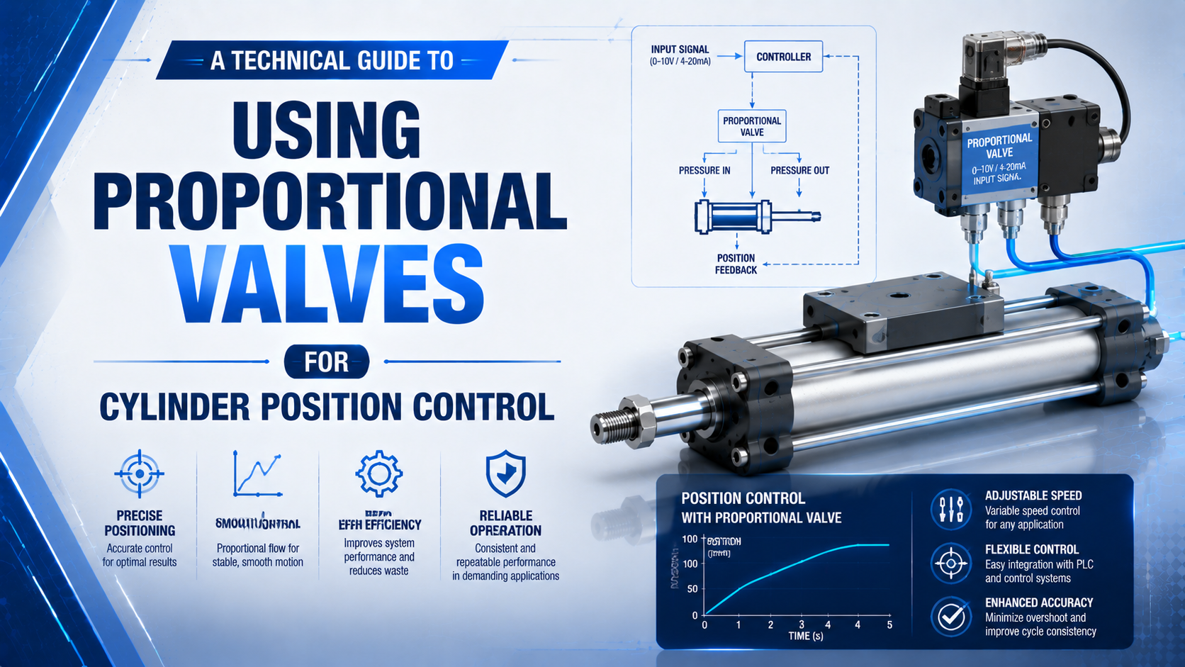
A proportional valve can regulate the direction and rate of airflow to a pneumatic cylinder, but the valve cannot position the cylinder by itself. A working closed loop also needs continuous position feedback, a controller, suitable mechanics, stable compressed air, and a test that defines acceptable motion under load.
The practical job is to make those parts behave as one axis. That means sizing the air path before tuning, verifying signal polarity and valve neutral at low energy, and judging the result from recorded command, position, pressure, and valve-output traces. A catalog accuracy number can’t replace that process.
Key Takeaways
- Festo specifies its MPYE as a 5/3 proportional directional valve used with an external position controller and displacement encoder.
- Valve hysteresis and bandwidth are component data, not cylinder-axis accuracy.
- Size both cylinder chambers and the complete air path before controller tuning.
- Approve the axis from measured error, overshoot, settling, repeatability, load, and fault response.
What Must a Pneumatic Position-Control Loop Contain?
Festo describes its MPYE as a 5/3 proportional directional valve and states that a precise pneumatic positioning system combines the valve with an external position controller and displacement encoder (Festo MPYE data sheet, 2025). The controlled object is therefore the complete axis, not the valve alone.
The position error is the difference between the commanded and measured locations:
Here, is position error, is the requested position, and is the sensor reading, all expressed in the same distance unit. The controller uses that error to command the valve, which changes chamber flow and moves the load.
Each block needs a clear boundary:
| Layer | Minimum engineering definition | Failure that it prevents |
|---|---|---|
| Command | Positions, profile, velocity and acceleration limits | Uncontrolled jumps between setpoints |
| Controller | Update time, output limits, tuning method, fault logic | Oscillation, saturation, or unsafe recovery |
| Valve | Directional function, flow, signal, neutral behavior, exhaust path | Wrong direction or insufficient correction authority |
| Mechanics | Bore, stroke, guide, load, orientation, friction, stops | Side load, flex, stick-slip, or load drop |
| Feedback | Measured datum, range, resolution, linearity, wiring | Correcting the wrong coordinate or losing position |
| Safety | Safe state, isolation, stored-energy release, brake if needed | Motion after a stop command or energy removal |
A reed switch can confirm an endpoint, but it doesn’t provide continuous position feedback. A pressure sensor can support force or fault monitoring, but chamber pressure isn’t a substitute for carriage position. The feedback sensor integration guide explains that distinction in more detail.
The Measurement Boundary: Valve Data Is Not Axis Accuracy
The 2025 MPYE data sheet lists maximum spool hysteresis of 0.4% and model-dependent limit frequencies from 70 to 115 Hz (Festo MPYE data sheet, 2025). Those numbers describe valve behavior under specified tests. They do not establish the positioning accuracy, repeatability, or settling time of a loaded cylinder axis.
Hysteresis, frequency response, input resolution, and nominal flow tell the controls engineer what the valve can do. The axis result also includes sensor error, controller sampling, seal friction, guide clearance, load variation, compressible volume, tube delay, supply-pressure movement, exhaust restriction, and fixture deflection.
This is why the same valve can perform differently on two machines. A short, rigid, horizontally guided axis with a stable payload may tune cleanly. Put the valve several meters away, double the dead volume, hang a vertical load, or introduce side loading, and the measured response changes even though the valve part number does not.
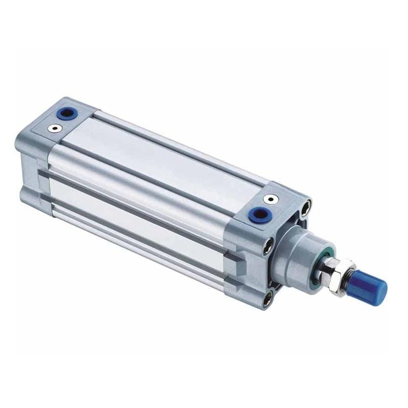
A cylinder is the mechanical plant in the loop. It does not become a positioning axis until the machine adds continuous feedback, control authority, guidance, and a defined safe state.
Before accepting any accuracy claim, ask five questions:
- What physical datum was measured: piston, rod, carriage, tool, or finished part?
- Was the result accuracy, repeatability, resolution, or in-position stability?
- What payload, speed, stroke region, pressure, temperature, and tube length were used?
- How many approach directions and cycles were tested?
- What instrument and uncertainty were used to verify the result?
The broader guide to proportional valves for precision motion control covers pressure, flow, and directional valve families. For position control, keep the selection narrower: the valve must meter both chamber paths and reverse motion through the commanded operating range.
How Should the Valve and Air Path Be Sized Before Tuning?
Festo publishes MPYE variants with standardized nominal flow ratings from 100 to 2,000 L/min and port sizes from M5 to G3/8 (Festo MPYE data sheet, 2025). That 20:1 catalog range shows why a valve must be sized from chamber demand and pressure conditions, not chosen by cylinder port thread alone.
For a first-pass extension estimate, calculate the normalized flow needed to fill the cap-end volume during the target time:
Here, is normalized volumetric flow, is cap-end piston area, is stroke, and is the intended stroke time. The pressures and are absolute chamber and reference pressures. The temperatures and are absolute chamber and reference temperatures in kelvin. Use a representative average chamber state, keep units consistent, and match the supplier’s normalization convention.
For retraction, use the annular rod-side area:
In this equation, is piston bore and is rod diameter. Extension and retraction demands differ because the effective areas differ. They may also need different controller limits because the same chamber pressure creates different force on each side.
These equations are screening tools, not valve selection guarantees. Published nominal flow is measured under a supplier’s reference conditions, while the installed axis contains fittings, tube, silencers, manifolds, meter-out restrictions, and changing cylinder pressure. Near a large pressure ratio, compressible flow can become choked, so raising downstream demand no longer produces a proportional flow increase. See the choked-flow guide before treating nominal L/min as available motion flow.
Use the Cylinder Flow Requirement Calculator to screen bore, stroke, and target time. Then use the Cv Flow Calculator to compare valve-path capacity at stated upstream and downstream conditions. Neither tool predicts closed-loop accuracy.
Check the installed path in this order:
- Measure dynamic inlet pressure at the valve while the cylinder moves.
- Record both supply and exhaust restrictions, including silencers.
- Keep the proportional valve close enough to limit dead volume where practical.
- Size tubing from inside diameter and length, not outside diameter alone.
- Check cap-end and rod-end motion separately.
- Confirm the valve retains useful bidirectional authority near the target, not only at full command.
If the axis reaches output saturation before it reaches the requested profile, tuning can’t create missing flow. The valve pressure-drop calculation guide is the next check when the command reaches its limit but the carriage remains slow.
A Safe Commissioning Sequence
ISO 4414:2010 covers significant pneumatic-system hazards and applies to design, installation, adjustment, operation, maintenance, and reliable use; ISO reports that the 2010 edition was confirmed in 2021 (ISO 4414, accessed 2026). Commissioning must therefore begin with the safe state and stored energy, not with aggressive controller gains.
Before applying air, document what the machine should do after power loss, sensor failure, communication loss, controller fault, or emergency stop. A closed-center valve may slow motion, but trapped air can still store energy and leakage can let a vertical load creep. If gravity can move the load, define the brake, counterbalance, restraint, or controlled exhaust strategy separately.
Use this staged sequence:
- Lock out and inspect mechanics. Verify mounting, guides, side-load control, end stops, sensor attachment, hose restraint, and the full travel envelope.
- Confirm the pneumatic schematic. Trace supply, working ports, exhausts, silencers, regulator, isolation valve, dump valve, and any pilot circuits. Do not infer ports from connector location.
- Verify electrical references without motion. Check supply voltage, analog common, shielding, grounding, controller scaling, and sensor plausibility.
- Reduce available energy. Use the equipment manufacturer’s commissioning procedure, conservative pressure, low output limits, and a clear exclusion zone.
- Jog away from hard stops. Command small movements and confirm that positive command produces positive measured motion.
- Test neutral and fault behavior. Observe the axis at zero command, disable, power loss, sensor disconnect, and controller timeout under controlled conditions.
- Increase speed and load in steps. Record every change. Do not tune at no load and approve the machine at full load without retesting.
- Run the production acceptance cycle. Include warm-up, both travel directions, expected payload range, and the actual fixture datum.
Why test the fault path so early? Because a sign error can make the controller drive harder in the wrong direction. Software output limits help, but they don’t replace physical risk controls, isolation, pressure relief, or a safe mechanical design.
The valve’s air-quality requirement must come from its own data sheet. For example, the cited MPYE specifies compressed air to ISO 8573-1 class [6:4:4] and does not permit lubricated operation (Festo MPYE data sheet, 2025). ISO 8573-1 defines purity classes for particles, water, and oil; it does not prescribe one universal filter rating for every proportional valve.
How Should Feedback, Neutral, and Signal Scaling Be Verified?
The MPYE family includes 0 to 10 V and 4 to 20 mA command variants, with a 17 to 30 V DC operating-voltage range (Festo MPYE data sheet, 2025). Similar-looking connectors can therefore carry different signal conventions. Verify the exact model, wiring, scaling, and neutral value before enabling cylinder motion.
Start by creating a signal map that spans the entire loop:
| Quantity | Controller value | Electrical value | Physical value |
|---|---|---|---|
| Position command | Engineering units | Internal data | Tool or carriage datum |
| Position feedback | Raw counts and scaled units | Voltage, current, or digital word | Measured travel |
| Valve command | Percent or signed word | Model-specific signal | Spool opening and direction |
| Pressure feedback | Scaled pressure | Sensor signal | Valve inlet or chamber location |
Verify sensor endpoints with an independent measurement. Then move the actuator slowly through several positions and check monotonicity, polarity, discontinuities, and lost counts. A sensor can have fine resolution yet still be mounted to the wrong datum or scaled with the wrong stroke.
Valve neutral needs the same discipline. Do not assume that a numeric midpoint creates zero cylinder velocity. Manufacturing tolerances, overlap, leakage, pressure imbalance, vertical load, unequal piston areas, and controller offsets can shift the command that produces minimum motion. Record the actual neutral region in both directions at representative pressure and temperature.
A practical low-energy test is to plot valve command and measured velocity while sweeping slowly through neutral. If velocity changes sign cleanly, the mapping is usable. If there is a wide inactive band followed by a sudden jump, the loop may need dead-zone handling, friction compensation, or a different valve size. Hiding that jump with more proportional gain usually creates hunting.
Finally, check saturation. The controller should know the permitted positive and negative output limits, and the integrator should not continue accumulating error when the command is pinned at a limit. That condition is called windup. It often appears as a long overshoot after the axis finally begins to move.
How Do You Tune Without Universal PID Numbers?
MathWorks’ real-time PID autotuning guidance uses target bandwidth and phase margin rather than a universal gain table, noting that greater phase margin can reduce overshoot while limiting response speed (MathWorks PID Autotuning, accessed 2026). Pneumatic tuning must likewise follow measured response, output limits, and the actual load.
A generic controller can be represented as:
Here, is valve command, , , and are controller gains in implementation-specific units, and is an optional feedforward term. The equation describes structure, not recommended numeric settings. Some commercial pneumatic positioners expose different parameters or perform tuning internally.
Tune only after mechanics, signals, pressure, and flow capacity pass their checks. Then use a repeatable procedure:
- Choose a modest test move. Stay away from hard stops and use the real sampling rate, filters, and output limits.
- Begin with integral and derivative action disabled if the controller permits it. Raise proportional action gradually until the response is useful but not continuously oscillatory.
- Add damping deliberately. Derivative action or a controller-specific damping parameter can reduce overshoot, but noisy feedback may require filtering.
- Add integral action slowly. Use it to remove persistent bias after the proportional response is stable. Apply anti-windup at output limits.
- Add feedforward only from measured need. Velocity or friction compensation can reduce following error, but it should not hide a wrong feedback sign or undersized valve.
- Repeat in both directions and across the load range. Unequal areas and gravity make one gain set behave differently on extension and retraction.
In our experience, the most informative question isn’t “What gain should I enter?” It is “Which trace shows the first unacceptable behavior?” If the valve command saturates, fix capacity or profile demand. If position moves in steps around zero velocity, investigate stiction and deadband. If pressure collapses at each move, inspect the air path before adding control gain.
Do not optimize one empty-axis move. Test small and large steps, both directions, representative dwell times, cold and warm operation, and the permitted payload range. A setting that looks fast in one trace may produce poor repeatability after seal temperature and breakaway friction change.
Step-Response Acceptance Metrics
MathWorks defines its default step-response rise time from 10% to 90% of the initial-to-final change and its default settling threshold as 2% of that change (MathWorks stepinfo, accessed 2026). Those are analysis conventions, not automatic machine tolerances; record the thresholds your process actually uses.
For every commanded position, record at least these metrics:
| Metric | Definition to freeze before testing | What it reveals |
|---|---|---|
| Rise time | Time between stated lower and upper fractions of the move | Speed of the main response |
| Peak overshoot | Maximum travel beyond the command, in distance and percent | Damping and process collision risk |
| Settling time | Time until error enters and stays inside the specified band | When the next machine step may start |
| Steady-state error | Remaining command-to-measurement difference after settling | Bias, leakage, load, or integral behavior |
| Repeatability | Spread of repeated final positions under stated conditions | Cycle-to-cycle consistency |
| Following error | Position error during a moving profile | Flow capacity and profile tracking |
| In-position stability | Motion within the dwell window | Hunting, noise, stiction, or poor neutral |
Do not collapse these into one “accuracy” number. A cylinder may repeat closely but stop at a biased location. Another may cross the target accurately yet take too long to settle. The process owner needs to decide which error creates a bad part, unsafe motion, or missed cycle time.
Test the sensor datum that matters to production. If tool deflection or carriage rotation changes the part location, a piston-position trace alone can look good while the process fails. Where the tolerance is tight, compare controller feedback with an independent measurement during acceptance.
Which Trace Identifies Hunting, Drift, or Slow Settling?
The MPYE data sheet gives maximum spool hysteresis of 0.4%, but a cylinder trace can also contain seal friction, pressure imbalance, sensor noise, output saturation, and mechanical play (Festo MPYE data sheet, 2025). Diagnose from synchronized signals rather than labeling every position error “bad tuning.”
Record command position, measured position, position error, valve command, supply pressure at the valve, and both chamber pressures when available. Use a common clock. A trend captured by separate instruments without synchronized time can hide cause and effect.
| Trace pattern | Likely mechanisms | First checks |
|---|---|---|
| Regular oscillation around target | Excess loop gain, delay, poor damping, noisy derivative action | Sampling time, filters, gain, valve distance, dead volume |
| Command pinned at its limit while position lags | Insufficient flow, pressure drop, aggressive profile, excess load | Dynamic inlet pressure, exhaust path, tubing, valve size |
| Long pause followed by a jump | Seal stiction, wide deadband, poor neutral compensation | Low-speed sweep, guides, seal condition, valve sizing |
| Slow drift during dwell | Leakage, vertical load, pressure imbalance, integrator bias | Chamber pressures, valve neutral, brake or load restraint |
| Direction-dependent error | Unequal piston areas, gravity, asymmetric friction or exhaust | Separate extend/retract traces and output limits |
| Position noise without physical motion | Sensor wiring, grounding, scaling, vibration, quantization | Raw signal, shield termination, independent measurement |
| Good cylinder feedback but bad part position | Guide play, fixture flex, wrong sensor datum | Measure the tool or part datum under load |
Hunting is not always excessive proportional gain. A small valve command may fail to overcome static friction, so error grows until the cylinder breaks free and overshoots. Reducing gain can calm the trace while leaving the underlying stick-slip problem untouched. Inspect motion at low velocity before accepting a software-only fix.
Drift also needs a load-path check. A closed-center spool is not a mechanical brake. Leakage across valve and cylinder seals can let a suspended mass move over time. If holding position is safety-related, use a risk-assessed restraint or brake rather than relying on normal control action.
Slow settling with a saturated output points back to capacity. Slow settling with a small alternating output near neutral points toward tuning, stiction, or deadband. Falling valve-inlet pressure during each move suggests a supply or distribution issue; the pressure-drop troubleshooting guide covers that upstream diagnosis.
Commissioning Records Make Position Claims Defensible
Enfield’s S2 description identifies three integrated elements in its cylinder positioning system: a proportional valve, sensors, and embedded control electronics (Enfield S2 positioning system, accessed 2026). A useful project record must extend that hardware list with mechanics, air conditions, software, load, and measured acceptance results.
Save enough information to reproduce the test after maintenance or a product change:
- Cylinder model, bore, rod diameter, stroke, mounting, guide, and moving mass.
- Valve model, flow variant, command type, firmware, porting, and neutral behavior.
- Sensor model, measurement range, scaled range, datum, and mounting method.
- Controller task period, filters, gains, feedforward, output limits, and anti-windup settings.
- Regulated pressure plus dynamic pressure at the valve inlet and relevant chambers.
- Tube inside diameter, length, fitting path, manifold, silencers, and exhaust restrictions.
- Motion profile, target positions, dwell, payload, orientation, and warm-up state.
- Acceptance thresholds, independent instrument, sample count, results, and raw traces.
- Safe-state behavior after disable, power loss, sensor fault, timeout, and emergency stop.
Change control matters. Replacing a valve with the same port size but a different flow curve, hysteresis, neutral overlap, or input type can invalidate the tuning. Changing tube length changes dead volume. Replacing a cylinder seal changes breakaway friction. Restore the recorded configuration, then rerun the agreed acceptance cycle.
For an RFQ, send the same boundary conditions before asking for a positioning guarantee. Include the motion profile and allowable settling time, not only stroke and “high accuracy.” If you need help checking a valve-and-cylinder combination, submit the recorded load, pressure, tube, feedback, and trace information through the technical contact page.
Pneumatic Cylinder Position Control FAQs
Festo’s documented MPYE range spans 100 to 2,000 L/min and uses external position control plus displacement feedback for pneumatic positioning (Festo MPYE data sheet, 2025). The five answers below keep that system boundary intact and avoid treating one valve specification as a universal axis result.
Can a proportional valve position a pneumatic cylinder without a sensor?
Not as a true closed-loop position axis. An open-loop command can influence speed, direction, or approximate travel time, but it cannot verify where the load stopped. Festo’s MPYE positioning description explicitly adds an external position controller and displacement encoder. Use endpoint switches only when the process needs discrete confirmation rather than continuous correction.
What positioning accuracy should I expect from a proportional valve system?
There is no defensible universal value. Valve hysteresis, sensor error, controller timing, friction, load, mechanics, tube volume, pressure variation, and the test datum all contribute. State the required tolerance, load, speed, settling time, temperature, approach direction, and sample count, then prove the complete axis with an independent acceptance measurement.
Is a 5/3 proportional directional valve always required?
A 5/3 proportional directional valve is a common choice for a double-acting cylinder because it can meter both directions and has a defined center function. It is not a universal rule. The correct circuit depends on actuator type, load, safe state, controller architecture, holding requirement, exhaust strategy, and the selected manufacturer’s operating instructions.
Can I retrofit an existing cylinder with closed-loop position control?
Often, but the retrofit is a system review rather than a valve swap. Confirm that the cylinder and guide can move smoothly, add a sensor that measures the correct datum, check controller compatibility, size supply and exhaust paths, define fault behavior, and test the real payload. Excess side load or stiction may make replacement more practical.
How do I know whether tuning or airflow is causing slow response?
Plot valve command, position, error, and dynamic inlet pressure on one time base. If command remains saturated while position lags, inspect valve capacity, tubing, exhaust, pressure drop, load, and profile demand first. If the output is not saturated but position oscillates or creeps near target, investigate tuning, neutral, feedback noise, stiction, and leakage.