

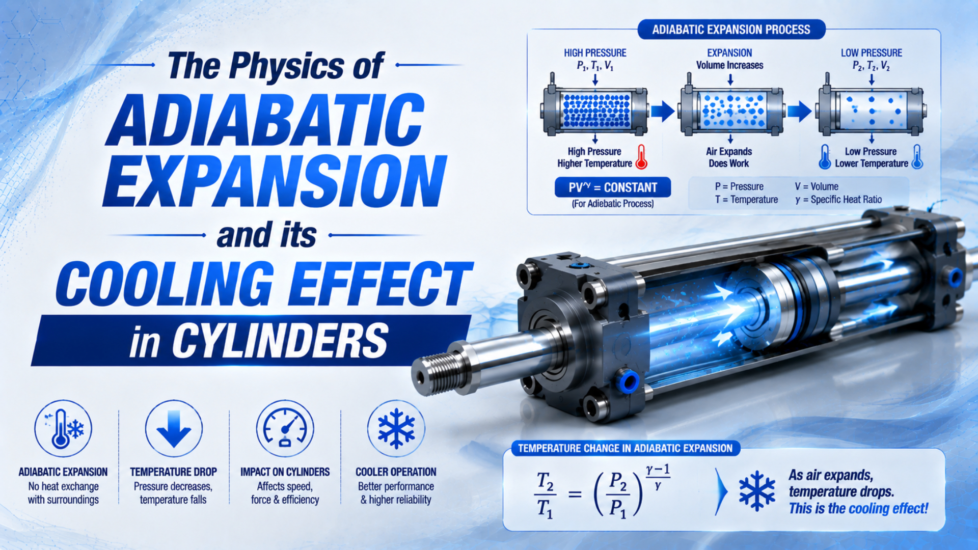
Adiabatic expansion can produce a very low ideal gas-temperature limit, but that limit is not the predicted surface temperature of a pneumatic cylinder. Real exhaust is transient, irreversible, and distributed across the chamber, valve, restriction, jet, and muffler. Frost also requires water, so pressure dew point matters as much as pressure ratio.
For example, starting with air at 100 psig and 70°F and ending at 14.7 psia produces an ideal isentropic endpoint of about -165.2°F. That calculation is a reference bound. It does not prove that a seal, barrel, valve body, or exhaust silencer reaches that temperature. In our experience, recording where frost first appears before the equipment thaws is more useful than photographing the entire cold circuit later. Cylinder-port, valve-body, and muffler frost point to different restrictions and heat-transfer histories.
Key Takeaways
- NASA’s ideal isentropic model gives about -165.2°F for air expanding from 100 psig at 70°F to atmospheric pressure.
- Adiabatic does not automatically mean reversible or isentropic.
- Ice forms only when local temperature crosses the water content’s dew or frost point.
- Diagnose the first cold location before changing the cylinder, valve, or dryer.
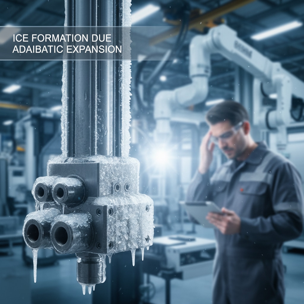
Illustrative fault symptom, not a claim that a cylinder body normally reaches the ideal gas-temperature endpoint.
What Is Actually Cooling During a Pneumatic Exhaust Event?
NASA’s ideal-gas equation of state connects four variables: pressure, volume, mass, and absolute temperature; SMC separately warns that a temperature decrease in pneumatic piping can cause internal condensation and wash away lubricant. During exhaust, the gas cools first; surrounding metal, seals, oil, and incoming heat respond on different time scales (NASA; SMC).
In a control volume, the ideal-gas relationship is:
Here, is absolute pressure, is volume, is gas mass, is the specific gas constant, and is absolute temperature. Pressure is proportional to temperature only when both mass and volume remain fixed. During cylinder exhaust, neither condition remains fixed: mass leaves, chamber volume may change, and heat crosses the wall.
Coldest gas may be located in the exhaust jet or immediately downstream of a restriction rather than uniformly inside the cylinder. Cold gas is not the same as cold metal. Barrel temperature is moderated by thermal mass, conduction into the end caps and mounting, ambient convection, repeated compression, and the duration between cycles. Adiabatic cooling means gas temperature falls as internal energy is converted or redistributed during an expansion with negligible heat transfer over the chosen time and control boundary. It does not mean every component in the circuit has one shared temperature.
Define the boundary before naming the process. The gas remaining in a cylinder chamber, the mass passing through a valve, and the free exhaust jet are three different control problems. Applying one closed-system formula to all three can produce a precise number for the wrong physical object.
Four Models Behind Adiabatic Expansion
MIT OpenCourseWare separates three ideal-gas paths: reversible adiabatic, isothermal, and free expansion. NASA derives the isentropic pressure-temperature relation for a calorically perfect gas. These models answer different questions; “fast exhaust” alone does not make a real valve-and-cylinder event reversible (MIT OpenCourseWare; NASA).
- Isothermal model. Sufficient heat transfer holds gas temperature constant. Treat it as the slow-process limit.
- Reversible adiabatic, or isentropic, model. No heat crosses the boundary and no entropy is generated. This produces the steepest ideal temperature prediction used in this article.
- Polytropic model. The relation represents an empirical path. The exponent must come from a defensible test or model; it is not a universal “normal pneumatic” value.
- Transient open-system model. Mass exits a changing chamber through valves and restrictions while heat crosses walls. This is the most faithful category for a working cylinder, but it requires time-dependent mass, energy, pressure, and heat-transfer data.
Adiabatic and isentropic are therefore not synonyms. Even without heat exchange, a process can generate entropy through friction, turbulence, mixing, shocks, or an irreversible pressure drop. Valve restriction matters because the gas upstream, gas in the throat, downstream jet, and solid body do not share one simple path. Throttling also needs care. An ideal steady throttling valve is commonly modeled as constant enthalpy, not as a reversible adiabatic expander. Air near room temperature can show a Joule-Thomson temperature change across a restriction, while the high-speed exhaust jet undergoes additional acceleration and mixing. Manufacturer geometry or measurements are needed for a full prediction. Apply the steady throttling model only across the valve boundary; by itself, it says nothing about transient chamber gas or metal temperature.
How Is the Ideal Adiabatic Expansion Temperature Limit Calculated?
NASA gives the isentropic relation for a calorically perfect gas, and NIST defines one standard atmosphere as 14.6959 psi. Converting 100 psig to 114.7 psia before using the equation changes the result materially; gauge pressure cannot be inserted directly into a pressure ratio (NASA; NIST).
Start with the required pressure conversion:
Under an ideal reversible adiabatic process:
In these equations, is gauge pressure, is local atmospheric pressure, and are the initial and final absolute pressures, and and are absolute temperatures. Near room temperature, is a common dry-air approximation. This worked example uses:
- Initial gauge pressure: 100 psig
- Initial absolute pressure: 114.7 psia
- Final absolute pressure: 14.7 psia
- Initial temperature: 70°F, or 294.26 K
- Absolute pressure ratio: 0.1282
- Ideal isentropic endpoint: 163.60 K, or about -165.2°F
- Ideal temperature decrease: about 235.2°F
The result is a limiting calculation for the gas path assumed. It is not an equipment rating, a typical drop, or a reason to select a -165°F seal. Chamber gas receives heat from the cylinder wall during blowdown, and the wall itself cannot respond instantaneously to the gas calculation.
A polytropic comparison uses:
With an illustrative , the same endpoints give about -83.6°F. That number shows sensitivity to the assumed path and is not a recommended design value; determine from an appropriate transient model or measured pressure and temperature history.
Use the pressure converter for units, but add the atmospheric offset when converting gauge pressure to absolute pressure. The compression ratio calculator is suitable only for ratio screening; it does not replace the temperature-path model.
Why Is Real Adiabatic Expansion Hardware Usually Warmer?
SMC advises that temperature decreases can cause condensation inside piping. Its cylinder manual uses 5°C or lower as an equipment warning threshold because local expansion can push internal regions below water’s 0°C freezing point. This is real-hardware guidance, not evidence for one universal exhaust-temperature drop (SMC technical information; SMC manual).
Several effects separate the ideal gas endpoint from measured hardware temperature:
- Heat transfer from solids. The barrel, end caps, valve block, tubing, and fittings return energy to the cold gas during and after exhaust.
- Finite blowdown time. Meter-out control can slow chamber depressurization and allow more wall heat transfer, although it also adds back pressure.
- Irreversibility. Turbulence and friction generate entropy.
- Distributed expansion. Part of the pressure drop occurs in the cylinder port, valve, fitting, silencer, and free jet rather than in one uniform chamber.
- Repeated cycling. A component may not recover to ambient temperature between cycles, making temperature a time-history problem.
- Thermal measurement limits. A slow surface probe can miss a brief gas transient. An infrared reading can also be biased by surface emissivity, viewing angle, reflected energy, and a cold spot smaller than the instrument’s measurement area.
Cooling also does not automatically reduce static cylinder force through “lower air density.” With port pressures and effective areas fixed, the pressure force remains the pressure difference multiplied by area. Cold conditions can still degrade dynamic performance through seal stiffness, lubricant viscosity, leakage, reduced flow capacity, and altered chamber-pressure history.
A useful double-acting force balance for cap-end extension is:
Here, and are gauge pressures relative to the same ambient reference, is piston area, and is rod-side annular area. Positive force points toward extension; and are positive resisting magnitudes. Thus, is the force left for acceleration, not catalog available force. Reverse the sign convention for retraction.
Select bore and pressure with the pneumatic cylinder theoretical-force guide, and diagnose dynamic flow limits with the guide to how choked flow limits cylinder speed.
Where Does Frost Form in a Pneumatic Circuit?
CAGI recommends selecting dryer performance from the lowest temperature seen by the air and gives an example using a pressure dew point 20°F below the lowest ambient temperature. ISO 7183 separately standardizes dryer performance parameters including pressure dew point, flow, pressure drop, and air loss (CAGI; ISO 7183).
Ice needs two conditions at the same location: water must be present, and local temperature must fall below the water’s freezing or frost threshold. No water means no ice. Relevant water content is described by pressure dew point at operating pressure, not just room relative humidity. After pressure reduction, the temperature and water-vapor partial pressure both change.
ISO 8573-1 defines compressed-air purity classes for particles, water, and oil, but a class number is not a substitute for application review (ISO 8573-1). Select a pressure dew point below the lowest temperature expected anywhere downstream, with a documented margin appropriate to the process and dryer controls.
A Diagnostic Map by Frost Location
Parker states that pneumatic mufflers used below freezing need moisture-free air. SMC uses 5°C as an equipment warning threshold because expansion can create local subzero regions where moisture freezes and damages seals or causes malfunction. Those limits make the first frost location a diagnostic clue (Parker; SMC).
| First cold or frosted location | Measure next | Likely mechanisms to test |
|---|---|---|
| Cylinder barrel or end cap | chamber pressure, surface and gas temperature, cycle timing | repeated blowdown, insufficient recovery time, internal water, cushion restriction |
| Cylinder port fitting | pressure immediately upstream and downstream, fitting bore | local restriction, undersized adaptor, high jet velocity |
| Directional valve body | both work-port pressures, spool path, valve duty | restrictive valve path, internal leakage, rapid repeated exhaust |
| Speed controller | upstream and downstream dynamic pressure, needle position | excessive meter-out restriction, contamination, incorrect orientation |
| Muffler or exhaust manifold | back pressure, muffler differential, contamination | clogged or undersized silencer, concentrated expansion, water accumulation |
| Long downstream tube | pressure and temperature along the run, ambient exposure | additional pressure loss, cold ambient, condensate pocket |
Use synchronized data where possible. At minimum, record supply pressure at the valve, both cylinder-port pressures, exhaust back pressure, ambient temperature, pressure dew point, surface temperatures at suspected points, cycle rate, and time from start-up to symptom.
A warmer cylinder does not clear the exhaust path. If the barrel remains near ambient but the muffler freezes, replacing cylinder seals or increasing barrel thermal mass addresses the wrong location. Measure across the exhaust restriction and inspect the dryer before altering actuator hardware. If the symptom occurs only after many cycles, plot component surface temperature against cycle count and recovery time; a first-stroke symptom after a long idle points instead toward trapped liquid water, ambient exposure, or a sudden local pressure drop. CAGI’s context in the pressure-dew-point guide explains why atmospheric dew point and pressure dew point are not interchangeable.
Which Countermeasures Match Which Root Cause?
CAGI says dryer selection should be based on required outlet pressure dew point, flow, inlet conditions, pressure drop, and operating cost; ISO 7183 covers dryers operating above 0.5 bar and up to 16 bar gauge. Therefore, “install a -40°F dryer” is not a universal answer (CAGI; ISO 7183).
Apply fixes to the measured root cause:
- Water content is too high. Verify dryer capacity at actual inlet temperature, flow, and pressure. Check drains, separators, filters, bypass valves, desiccant condition, and downstream piping. Specify pressure dew point from the coldest point of use, not a blanket value.
- The exhaust device is restrictive. Measure back pressure and pressure drop across the muffler or manifold. Clean or replace a contaminated element and size the exhaust path from the valve maker’s data. Do not remove a silencer without completing the machine’s noise and safety review.
- The meter-out setting is excessive. Adjust with the real load and stability requirement. More restriction can slow the piston and allow more chamber heat transfer, yet it can also create back pressure and a colder local jet at the needle.
- The valve or fitting is undersized. Compare dynamic pressure on both sides of the suspected component and use its tested flow data. A larger thread does not guarantee a larger internal flow area.
- The cycle provides too little thermal recovery. Evaluate a larger component body, conductive mounting, staged motion, reduced unnecessary pressure, or longer dwell. Confirm cycle time and force after every change.
- Elastomer or lubricant is outside its limit. Use the component maker’s dynamic low-temperature rating, media compatibility, and lubrication guidance. Parker’s O-ring handbook distinguishes TR-10 behavior from practical dynamic sealing limits, so a material label alone is insufficient (Parker O-Ring Handbook).
- Ambient temperature is the main driver. Protect exposed lines and components, eliminate low-point condensate traps, and follow the cold-weather pneumatic-system guide.
Avoid treating larger exhaust ports as a way to “slow expansion.” More effective exhaust area normally speeds chamber blowdown. It may reduce pressure loss and move the coldest location, but its impact on peak gas and surface temperatures depends on timing, back pressure, and heat transfer. Retest the motion after any flow-path change.
Commissioning Checklist for High-Cycle Circuits
CAGI recommends limiting total system pressure drop to 10% or less in a well-designed system, and the DOE sourcebook treats supply, distribution, and demand as one system. A defensible commissioning record therefore combines dryer performance, dynamic pressure, temperature, cycle timing, and component limits rather than accepting one no-load shop test (CAGI; DOE).
Before release:
- Record ambient minimum and maximum temperatures, including start-up and washdown conditions.
- State the required pressure dew point and sensor location.
- Verify dryer outlet, drains, filters, and distribution low points at peak demand.
- Record valve-inlet, both cylinder-port, and exhaust pressures during extension and retraction.
- Measure temperature at the chamber port, valve body, speed controller, and muffler. Record sensor type, response time, attachment method, sample rate, infrared emissivity setting, and the exact point observed.
- Run enough consecutive cycles to reach a repeatable thermal condition.
- Check extension and retraction speed, cushion behavior, impact, and stability.
- Confirm dynamic low-temperature ratings for the seal compound and lubricant, plus the limits of tubing, valves, silencers, fittings, and sensors.
- Inspect for condensation or frost before it melts, then document the first location.
- Repeat the same test after each corrective change.
Use the cylinder seal material-selection guide for temperature-sensitive sealing decisions. If the cold event coincides with falling port pressure or slow motion, inspect the full pneumatic pressure-drop path. Acceptance should be application-specific: stable motion and force, acceptable back pressure, no water-related restriction, and temperatures inside every component’s rated dynamic range. If you need a circuit review, send the valve model, cylinder size, tubing, cycle trace, pressure dew point, ambient range, and frost-location photos through the technical contact page.
Pneumatic Adiabatic Cooling FAQs: What Should Engineers Verify?
NASA’s isentropic equation gives a model boundary, while CAGI’s dryer example places pressure dew point 20°F below the lowest ambient temperature. These facts frame the FAQ answers: calculate with absolute values, then verify real pressure, temperature, moisture, timing, and frost location on the machine (NASA; CAGI).
Can a pneumatic cylinder really reach -165°F during exhaust?
The gas has an ideal isentropic endpoint near -165.2°F for the stated 100 psig, 70°F example, but that is not a predicted cylinder-surface temperature. Real blowdown includes heat from the wall, mass loss, irreversible valve flow, and mixing. Measure the gas or surface at the relevant location and response time.
Is adiabatic expansion the same as throttling through a valve?
No. Reversible adiabatic expansion is isentropic, while an ideal steady throttling valve is modeled as constant enthalpy. A pneumatic exhaust event can include chamber blowdown, valve throttling, jet acceleration, and ambient mixing. Use each model only for its defined control volume, then confirm temperatures experimentally.
Does dry compressed air eliminate the cooling problem?
Dry air prevents water-related condensation and ice only when its pressure dew point remains below the coldest local temperature with suitable margin. It does not prevent gas cooling, seal stiffening, lubricant viscosity change, or thermal contraction. Verify both dryer performance and every component’s dynamic low-temperature limit.
Should I restrict exhaust flow to stop icing?
Not automatically. Meter-out restriction can lengthen blowdown and increase heat transfer from the wall, but it also raises exhaust back pressure and creates a concentrated pressure drop at the needle. Adjust only after measuring motion, both chamber pressures, exhaust back pressure, and the first cold location.
Do rodless cylinders inherently experience less adiabatic cooling?
No universal rule supports that conclusion. Housing mass, port geometry, sealing concept, stroke volume, valve path, cycle rate, load, and mounting all affect the thermal response. Compare the exact rodless and rod-style designs using identical pressure, timing, moisture, and temperature measurements rather than cylinder category alone.
Sources and technical references
- NASA Glenn Research Center, Isentropic Compression or Expansion, ideal-gas isentropic pressure-temperature relation. Accessed 2026-07-19.
- NASA Glenn Research Center, Equation of State, ideal-gas pressure-volume-temperature relationship. Accessed 2026-07-19.
- MIT OpenCourseWare, Lecture 7: Ideal Gas Processes, reversible adiabatic, isothermal, and free-expansion models. Spring 2021.
- CAGI, Compressed Air & Gas Handbook, Chapter 3, air treatment and pressure-dew-point selection. Accessed 2026-07-19.
- ISO, ISO 8573-1:2010, compressed-air purity classes for particles, water, and oil. Accessed 2026-07-19.
- ISO, ISO 7183:2007, compressed-air dryer specifications and testing. Accessed 2026-07-19.
- Parker Hannifin, O-Ring Handbook, low-temperature elastomer behavior and sealing limits. Accessed 2026-07-19.
- Parker Hannifin, Pneumatic Accessories, muffler guidance for below-freezing service. Accessed 2026-07-19.
- SMC, Condensation in Pneumatic Systems, condensation and lubricant washout from temperature decrease. Accessed 2026-07-19.
- SMC, Pneumatic Cylinder Operation Manual, freezing risk at low fluid temperatures. Accessed 2026-07-19.
- U.S. Department of Energy, Improving Compressed Air System Performance, system-level compressed-air assessment. Accessed 2026-07-19.
- Festo, Air Preparation, application-specific compressed-air treatment. Accessed 2026-07-19.
- NIST, Pressure and Gas Flow Unit Conversions, standard atmosphere and pressure conversion. Updated 2025.