

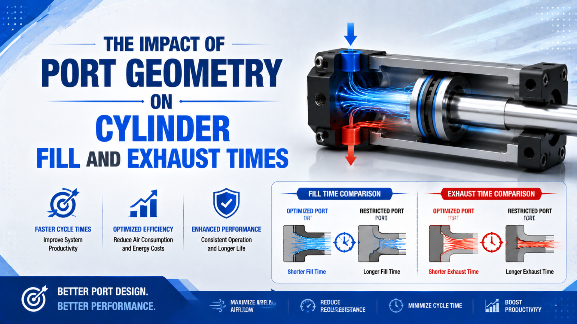
Pneumatic cylinder port geometry affects fill and exhaust time, but the outside thread size does not set cylinder speed by itself. The controlling restriction may be a smaller cross-drilled passage, fitting bore, speed controller, valve spool window, tube, cushion channel, or exhaust silencer elsewhere in the active flow path.
That distinction matters because doubling a circular passage’s area does not guarantee twice the mass flow or half the stroke time. Air is compressible, pressure changes throughout the stroke, and several restrictions act in series. Size the motion demand first, compare tested flow data, then confirm the result with dynamic pressure and timed strokes.
Key Takeaways
- SMC states that cylinder speed depends on airflow and piston area, while port and tubing sizes also affect the result.
- ISO 6358 characterizes compressible flow with tested component data, not thread diameter alone.
- Treat every 2x-area claim as a geometric screen until the complete supply and exhaust paths pass a timed test.
What Does Port Geometry Actually Control?
SMC publishes the first-pass relation s = 28.8q/A for cylinder speed, with constant inlet pressure, and then warns that port and tubing sizes also affect motion (SMC, Control Air Flow of Cylinders, accessed 2026). Port geometry therefore influences available flow, not speed in isolation.
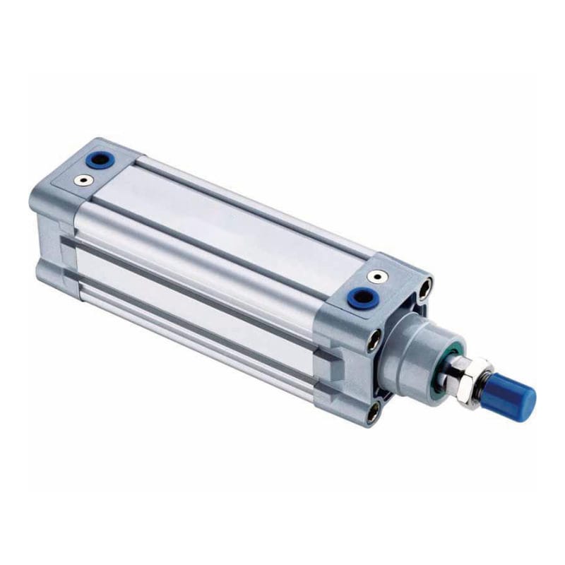
Pneumatic cylinder port geometry is the complete internal shape between the external connection and the working chamber. It includes the threaded entry, spotface, fitting interface, drilled bore, cross-hole, corner transition, casting or extrusion passage, cushion path, and any local recess where flow changes direction.
The relevant dimensions are not always visible from outside. A G1/4 or 1/4 NPT label identifies a connection standard and nominal size. It does not disclose the fitting’s internal bore, the smallest drilled passage in the end cap, or the effective conductance of the assembled path.
Port geometry can affect five things:
- Effective flow capacity: the mass flow available at a stated upstream pressure, downstream pressure, and temperature.
- Local pressure loss: the pressure consumed by changes in section, bends, edges, and internal friction.
- Dead volume: the volume between the valve and chamber that must pressurize or vent before useful motion develops.
- Flow direction sensitivity: a passage, check element, or cushion path may behave differently during extension and retraction.
- Manufacturing consistency: burrs, drill breakthrough, casting shift, contamination, or an incorrect plug can change one unit without changing the catalog thread.
For the related bore-side relationship, see how cylinder bore changes force, volume, and fixed-flow speed. Bore determines the chamber demand. Port geometry helps determine whether the circuit can satisfy it.
The port should be treated as a measured flow component, not a hole with a label. A drawing dimension can control minimum metal removal, but only tested conductance or a validated manufacturer flow curve captures all of the three-dimensional losses in the finished passage.
Port Thread Size Is Not Flow Capacity
ISO 6358-1 was confirmed in 2022 and received a second measurement-uncertainty amendment in 2026. It tests pneumatic components with fixed or variable internal flow paths to determine compressible flow characteristics (ISO 6358-1; 2026 amendment). That framework separates connection identity from measured capacity.
A thread callout is still necessary. It controls interchangeability, sealing method, engagement, spotface, and fitting selection. It is simply not a flow rating. Two fittings with the same male thread can have different tube sizes, internal bores, elbows, seals, and release mechanisms. Two cylinder end caps can use the same female thread while containing different cross-drilled passages.
Use three separate fields in a technical comparison:
| Field | What it tells you | What it does not prove |
|---|---|---|
| Port thread | Mechanical connection and nominal size | minimum internal bore or mass flow |
| Minimum physical passage | Smallest inspected diameter or area | losses from bends, entrances, roughness, or changing pressure |
| Tested flow characteristic | Capacity under defined pressure and temperature conditions | complete cylinder stroke time under load |
This explains why enlarging an adaptor can fail to improve timing. The new fitting may expose the same end-cap drill, or the directional valve and meter-out controller may remain smaller restrictions. Conversely, a compact connection can perform well when the internal path is short, smooth, and supported by appropriate tested flow data.
ISO 15552 provides a useful boundary. The current 2018 edition covers detachable-mounting cylinders from 32 mm to 320 mm bore at a maximum rated pressure of 1,000 kPa, with basic, mounting, and accessory dimensions for interchangeability (ISO 15552, confirmed 2025). Interchangeable external dimensions do not remove the need for application flow verification.
Why Doesn’t Four Times the Area Mean Four Times the Flow?
ISO 6358-3, confirmed in 2025, calculates overall flow characteristics for systems made from components and piping with known flow characteristics. It covers both subsonic and choked behavior (ISO 6358-3). The standard’s system approach is why a single geometric area ratio cannot become a universal flow or time multiplier.
The circular area of a physical passage is:
Here, is geometric passage area and is the measured passage diameter. For two circular passages, the geometric ratio is:
This equation is valid geometry. It does not say that mass flow follows the same ratio. Actual pneumatic flow also depends on upstream absolute pressure, downstream absolute pressure, gas temperature, discharge behavior, passage length, surface condition, bends, entrances, and whether the controlling throat is choked.
At low pressure loss, a larger passage often reduces restriction. As the pressure ratio changes, however, its improvement does not remain proportional to area. Once a different component becomes the smallest effective restriction, enlarging the cylinder port further produces little change in the complete path.
The original “4x faster” interpretation also confuses velocity, flow, and time:
- Local gas velocity can rise or fall as pressure and section change.
- Mass flow is what fills or empties the chamber with air.
- Piston speed depends on chamber flow divided by effective piston area, plus load and pressure effects.
- Stroke time includes valve response, pressure buildup, acceleration, steady travel, cushioning, and stopping.
For the deeper sonic limit, use the dedicated guide to choked flow and maximum pneumatic cylinder speed. This article keeps the focus on the cylinder’s local connection and internal passage.
How Do Fill and Exhaust Paths Differ During Motion?
SMC identifies exhaust-flow control as the common way to regulate pneumatic actuator speed because changing back pressure changes piston motion (SMC, Control Air Flow of Cylinders, accessed 2026). That does not mean every cylinder needs an exhaust port 25% larger than its supply port.
On a double-acting cylinder, both end-cap ports alternate roles:
- During extension, the cap-end port admits air and the rod-end port exhausts.
- During retraction, the rod-end port admits air and the cap-end port exhausts.
The same physical port is therefore a supply path on one stroke and an exhaust path on the other. Any intentional asymmetry should come from a documented duty requirement, tested flow data, and the complete control circuit, not from a universal diameter ratio.
Extension and retraction can still need different flow. A single-rod cylinder has full piston area on the cap end and annular area on the rod end. At the same speed and pressure basis, the larger cap-end chamber normally requires more fill flow per millimetre of travel. Meanwhile, the exhausting chamber contains compressed air whose pressure changes as the piston moves.
Meter-out control deliberately restricts exhaust to stabilize motion. Too much restriction raises back pressure, reduces the net pressure differential across the piston, and extends the stroke. Too little restriction can allow unstable acceleration, especially with an overhauling or changing load. The related meter-out circuit guide covers that control strategy.
A quick exhaust valve can shorten the exhaust path when long tubing or a directional valve is the proven restriction. It does not enlarge the cylinder’s internal port or correct a restrictive cushion passage.
A Port Is One Link in a Series Flow Path
CAGI recommends no more than 10% pressure drop from compressor discharge to a point of use in a well-designed plant system, and it lists piping, fittings, filters, dryers, and other components as contributors (CAGI, Technical Brief on Pressure Drop, accessed 2026). Machine-level restrictions also accumulate in series.
The active supply path may include a regulator, manifold, directional valve, tube, elbow, speed controller, fitting, threaded port, cross-drill, and chamber entrance. The exhaust path begins at the opposite chamber and may add another fitting, controller, valve spool passage, manifold gallery, and silencer.
Do not rank restrictions by appearance. A large thread can hide a small cross-hole. A compact valve can have better tested flow than a visibly larger one. An open needle can still contain a narrow elbow. Compare manufacturer flow data and measure dynamic pressure before deciding which part to enlarge.
How Much Flow Does the Cylinder Need?
SMC’s model-selection example requires approximately 350 L/min (ANR) for a 50 mm bore cylinder operating at 0.5 MPa and 500 mm/s (SMC, Air Cylinders Model Selection, accessed 2026). That demand belongs upstream of any decision about port, fitting, tube, or valve capacity.
For a moving cylinder, a useful first-pass free-air demand estimate is:
Here:
- is the estimated flow on the stated normal or standard reference basis.
- is full piston area for extension or annular area for retraction.
- is stroke.
- is target travel time.
- is estimated absolute chamber pressure during travel.
- is the absolute pressure at the selected reference condition.
This is a demand estimate, not a timing guarantee. It does not model valve response, tube dead volume, heat transfer, changing chamber pressure, seal friction, load acceleration, or end cushioning. It does provide the correct starting question: what flow must reach or leave each chamber to meet the target?
State the reference basis beside every standard-flow value. NIST defines gas-flow conversions using specified pressure and temperature conditions, and warns that sccm can assume a different temperature in some uses (NIST, Pressure and Gas Flow Unit Conversions, updated 2025). An unlabeled L/min or SCFM value is incomplete comparison data.
If available flow is already known, use the Cylinder Speed Calculator as a first-pass comparison. For valve selection, follow the manufacturer’s pneumatic method or tested ISO 6358 data. Parker’s worked example uses a 3.25-inch bore, 12-inch stroke, 80 psig supply, and one-second target to calculate a required valve Cv of 1.06 (Parker, Pneumatic Valve Engineering Data, accessed 2026).
That example does not convert a port diameter into a stroke time. It begins with cylinder area, stroke, pressure, permitted pressure drop, and target time. Use the same order for an end-cap port review.
What Port Features Should a Drawing Specify?
ISO 15552 covers a 32-320 mm bore series and a maximum rated pressure of 1,000 kPa, but its published scope is basic, mounting, and accessory interchangeability (ISO 15552, confirmed 2025). A build-ready port drawing still needs local geometry, cleanliness, inspection, and functional flow requirements.
For a standard or replacement cylinder, specify the following as applicable:
- Connection standard and size: G, NPT, metric, or other thread; class; depth; spotface; sealing method; and orientation.
- Minimum passage geometry: finished bore, cross-drill diameter, breakthrough location, bend or intersection, and any prohibited ledge.
- Transition requirements: chamfer or radius where functionally needed, while preserving thread strength, sealing land, and wall thickness.
- Cushion relationship: separate the unrestricted chamber connection from the adjustable cushion path. Identify the flow route in each cushion state.
- Edge and cleanliness limits: no loose burrs, chips, casting flash, blocked intersections, damaged threads, or sealant inside the flow path.
- Pressure integrity: proof or leakage test, plug specification, and acceptance criteria for drilled galleries.
- Functional flow data: sonic conductance and critical pressure ratio, Cv using an approved pneumatic method, or a supplier flow curve at stated test conditions.
- Traceability: inspection plan, sampling frequency, drawing revision, process lot, and nonconformance disposition.
In our experience reviewing replacement cylinders, the missing value is often the internal cross-drill, not the external thread. A supplier matches the connection and mounting envelope, yet the new end cap contains a smaller passage or a different cushion intersection. The cylinder fits, but its pressure trace and stroke time change.
From our work comparing replacement drawings, we found that recording the minimum passage and the cushion intersection prevents more ambiguity than adding another generic “high-flow” note. The drawing becomes inspectable, while the functional flow requirement remains available for assembly-level acceptance.
Request a section view for custom end caps. For a standard catalog cylinder, request the manufacturer’s tested flow or speed-selection data rather than demanding proprietary internal dimensions that may not be published. The goal is functional equivalence, not reverse engineering for its own sake.
How Can You Diagnose a Port Restriction?
CAGI recommends adding pressure-monitoring taps because every flowing system develops losses. Its plant-level target is no more than 10% pressure drop to the point of use (CAGI, accessed 2026). At machine level, synchronized dynamic measurements reveal whether the cylinder port consumes a meaningful share.
Use a repeatable test:
- Record bore, rod, stroke, load direction, target time, actual extension time, and actual retraction time.
- Record valve model, active port path, tube ID and length, fittings, controllers, mufflers, and cushion settings.
- Install fast-response pressure sensors at the valve inlet and both cylinder ports. A temporary point immediately upstream of the port adaptor can isolate the adaptor and end-cap region.
- Log pressure and position or elapsed time through the moving part of both strokes.
- Change one restriction at a time. Repeat the same load, supply setting, and controller position.
- Inspect removed fittings and end-cap passages for sealant, chips, burrs, corrosion, collapsed tube, or mismatched bore.
| Pressure and timing pattern | Port-related interpretation | Check before machining |
|---|---|---|
| Large drop before the cylinder port in one direction | fitting, controller, tube, or valve path may be limiting | substitute a tested higher-flow upstream path |
| Pressure stays high before the port but chamber pressure responds slowly | adaptor, end-cap passage, cushion path, or sensor location is suspect | verify cushion state and inspect the internal route |
| Both port pressures look adequate but motion remains slow | load, friction, guide, seal, or cushioning may dominate | mechanical inspection and force balance |
| Only the final part of the stroke slows | end cushion is likely active | open or verify cushion adjustment within safe limits |
| A quick exhaust changes little | cylinder port, cushion, load, or supply side may remain limiting | compare before-and-after traces |
For a full diagnostic treatment, see how pressure drop across a pneumatic valve is calculated and how back pressure affects pneumatic equipment.
A port restriction is proven by a localized pressure loss that changes with flow and direction. A static gauge after the piston stops cannot show it because the chamber has time to equalize. Capture pressure while the piston is moving, then relate each loss to the same timed stroke.
When Should You Enlarge or Redesign a Port?
Parker’s one-second cylinder example produces a required Cv of 1.06 only after bore, stroke, pressure, and allowed pressure drop are defined (Parker, accessed 2026). Enlarge a port only after the target demand and measured restriction show that the end-cap path is inadequate.
A redesign is justified when:
- the port or internal passage consumes a material part of the dynamic pressure budget;
- upstream and downstream components already meet the demand;
- the cushion, seal, load, and guidance system are not the controlling causes;
- sufficient wall thickness, thread engagement, sealing land, and proof-pressure margin remain;
- the revised end cap can be cleaned, inspected, and qualified consistently;
- a timed A/B test confirms the improvement without unacceptable impact or instability.
Do not drill an assembled cylinder casually. Chips can enter the chamber, burrs can damage seals, and a larger passage can intersect a cushion bore, tie-rod hole, mounting thread, or pressure gallery. Modification may also void the manufacturer’s rating and traceability. Replace the end cap or cylinder when the structural and cleanliness controls cannot be restored.
Before changing metal, try reversible tests. Remove a clogged silencer, substitute a shorter larger-ID tube, use a verified higher-flow fitting, open the speed controller within a safe range, or bypass a suspected adaptor. Apply one change at a time and retain the pressure trace.
Increasing supply pressure is not a clean substitute. It changes cylinder force, air demand, impact energy, leakage, and component stress. The flow coefficient guide explains why capacity should be matched at the intended pressure conditions.
What Does a Port-Screening Example Show?
A hypothetical 4 mm passage has 12.6 mm² of geometric area, while a 6 mm passage has 28.3 mm². The area ratio is 2.25. ISO 6358-3 still requires the known flow characteristics of the system components to estimate overall compressible flow, so 2.25 is not a promised flow or timing ratio.
Assume two replacement end caps use the same external G1/4 connection. One has a verified 4 mm controlling cross-drill; the other has a 6 mm cross-drill with adequate wall thickness. Geometry gives:
This result supports one conclusion: the 6 mm cross-drill provides 2.25 times the physical area at that location. It does not support “2.25 times more air” or “56% less stroke time.”
Now place a 3.5 mm effective restriction in the upstream speed controller. Both end caps see the same smaller controlling element, so enlarging the end-cap cross-drill may make almost no measurable difference. Remove that upstream restriction, and the port change may become important. The controlling element shifts as the circuit changes.
The correct acceptance test therefore has three layers:
- Geometry: inspect minimum passage, intersections, wall thickness, burrs, and cleanliness.
- Flow: compare tested component or assembly capacity at defined pressure and temperature conditions.
- Motion: run the actual cylinder with the same load, valve, tube, controller, pressure, and cushion settings, then compare pressure traces and stroke time.
That hierarchy keeps a valid area calculation from becoming an invalid production promise.
Final Engineering Decision
ISO 6358-3 treats pneumatic capacity as a system of components and piping, while SMC states that port and tube sizes are only part of the cylinder-speed result. The decision rule is direct: calculate chamber demand, identify the active restriction, specify measurable port features, and verify the finished assembly with dynamic pressure and timed motion.
Use thread size for mechanical compatibility. Use minimum passage geometry for manufacturing control. Use sonic conductance, critical pressure ratio, Cv, or a manufacturer flow curve for capacity screening. Use the real cylinder test for acceptance.
A larger port is valuable when it removes the controlling restriction. It is wasted machining when another component remains smaller. Worse, it can reduce wall thickness, disturb cushioning, introduce contamination, or create unstable motion if changed without a complete review.
If a supplier cannot provide the necessary passage or flow data, send the cylinder model, section drawing, operating conditions, dynamic pressure trace, and timed stroke through the technical contact page for an application review.
FAQs About Port Geometry and Cylinder Timing
SMC’s published speed relation uses airflow and piston area, but it also names port and tubing size as additional influences. These five answers apply that distinction: an external thread identifies the connection, tested flow data describes capacity, and dynamic pressure plus stroke time determines whether the port matters in the real machine.
Does a larger cylinder port always make the cylinder faster?
No. A larger port helps only when the original port or internal end-cap passage is a controlling restriction. Valve passages, fittings, tubing, speed controllers, silencers, cushioning, load, and friction can still set the speed. Compare required chamber flow with tested capacity, then confirm the change with the same timed stroke and pressure trace.
Can I compare pneumatic ports by thread size alone?
No. Thread size describes the mechanical connection, not the smallest internal bore or tested conductance. Fittings and end caps with the same thread may have different cross-drills, elbows, seals, and passage lengths. Record the thread, minimum physical passage, and functional flow data as separate procurement fields.
Should the exhaust port be larger than the fill port?
There is no universal percentage or diameter ratio. On a double-acting cylinder, each port alternates between supply and exhaust as motion reverses. Size both active paths from chamber demand, control method, valve data, and allowable back pressure. Intentional asymmetry needs manufacturer evidence or a validated application test.
How can I tell whether the cylinder port is the bottleneck?
Measure pressure dynamically on both sides of the suspected region while recording stroke time. A repeatable flow-dependent pressure loss localized to the adaptor or end-cap passage supports the diagnosis. If chamber pressure responds normally, inspect the load, guides, seals, cushion, opposite exhaust path, and valve before modifying the cylinder.
What information belongs in a port-geometry RFQ?
Include connection standard, thread depth, spotface, sealing method, minimum internal passage, cross-drill location, transition limits, cushion route, wall thickness, deburring, cleanliness, leakage or proof test, and required flow evidence. Also provide bore, rod, stroke, pressure, load, target time, valve, tube, controller, and acceptance-test conditions.
Sources and technical references
- ISO, ISO 6358-1:2013, steady-state flow testing for pneumatic components with compressible fluids. Confirmed 2022; accessed 2026-07-19.
- ISO, ISO 6358-1:2013/Amd 2:2026, evaluation of measurement uncertainty. Published 2026; accessed 2026-07-19.
- ISO, ISO 6358-3:2014, calculation of system flow characteristics from known component and piping characteristics. Confirmed 2025; accessed 2026-07-19.
- ISO, ISO 15552:2018, basic, mounting, and accessory dimensions for 32-320 mm detachable-mounting cylinders rated to 1,000 kPa. Confirmed 2025; accessed 2026-07-19.
- SMC, Control Air Flow of Cylinders, cylinder speed, airflow, piston area, port size, tubing, and meter-out control. Accessed 2026-07-19.
- SMC, Air Cylinders Model Selection, required flow example for a 50 mm bore cylinder at 500 mm/s. Accessed 2026-07-19.
- Parker Hannifin, Pneumatic Valve Products Engineering Data, Cv sizing method and one-second cylinder example. Accessed 2026-07-19.
- CAGI, Technical Brief on Pressure Drop, pressure-drop contributors, monitoring taps, and system guidance. Accessed 2026-07-19.
- NIST, Pressure and Gas Flow Unit Conversions, pressure conversion and standard gas-flow reference conditions. Updated 2025; accessed 2026-07-19.