

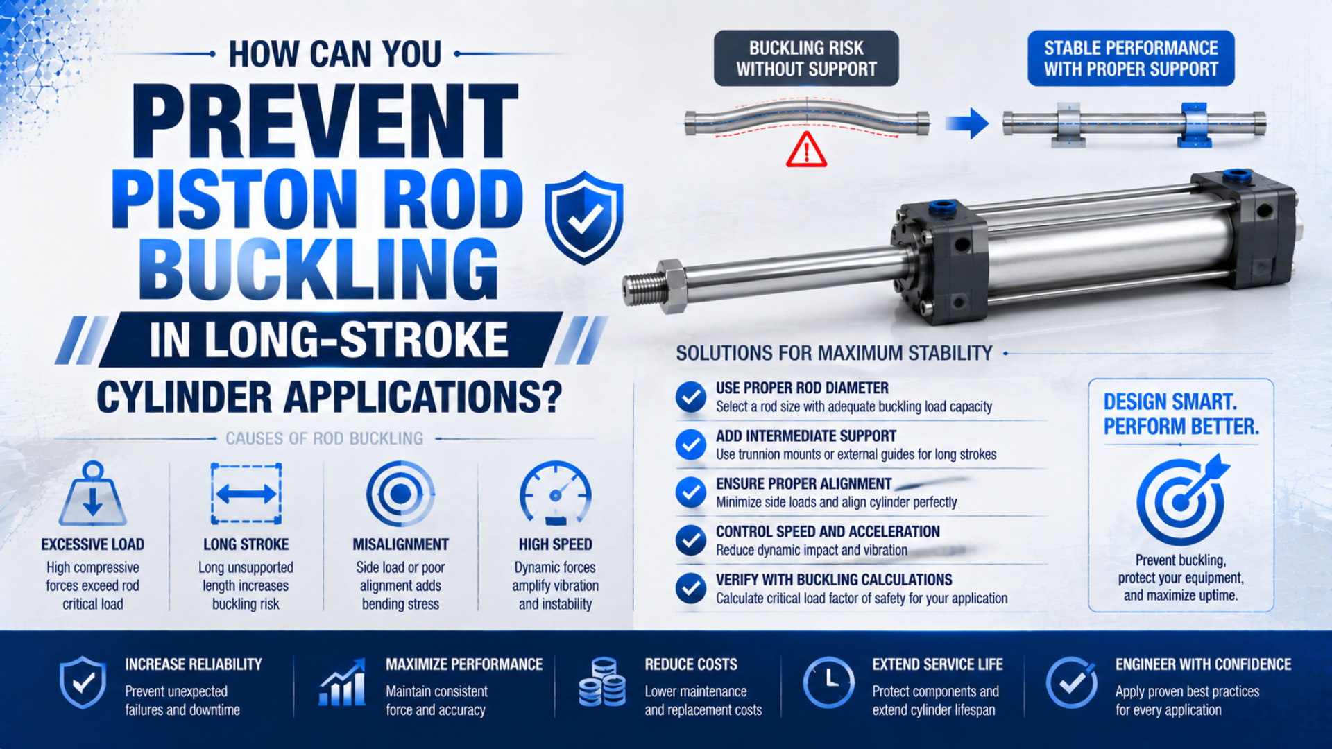
Prevent piston rod buckling by checking the largest possible compression force against both an Euler screening calculation and the cylinder manufacturer’s stroke-versus-load limit. Use the actual unsupported rod length and mounting condition, not stroke alone. Then control misalignment and side load separately. If the required margin is unavailable, shorten the support length, increase rod diameter, change mounting, add an external guide, or select a rodless architecture.
Key Takeaways
- Treat maximum cylinder thrust as a possible buckling load, even when the normal payload is light.
- Buckling capacity rises with rod diameter to the fourth power and falls with effective length squared.
- Euler math screens the rod; the exact manufacturer’s chart governs final cylinder selection.
This article is a structural sizing workflow, not a general cylinder comparison. For architecture tradeoffs, see rodless versus standard cylinders. For long conveyor axes, start with the dedicated rodless cylinder conveyor guide.
What Is Piston Rod Buckling, and When Is It Possible?
Euler buckling is a stability failure of a long, slender member under axial compression. MIT’s mechanics laboratory describes the critical load as a function of stiffness and effective length, with the end conditions incorporated through effective length (MIT OpenCourseWare, retrieved 2026-07-19).
Euler critical load is the ideal axial compression load at which a straight elastic column becomes unstable. A cylinder rod is vulnerable when it is extended and pushing. During a pulling stroke, the rod is primarily in tension, so classical compression buckling is not the governing rod failure mode. A short, thick rod can still fail by yielding or overload, while a long, slender rod can become laterally unstable below its material yield strength.
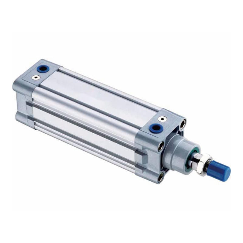
Do not classify every bent rod as an Euler failure. An off-center attachment, inadequate external guidance, impact against a stop, or a moving load that rotates can bend the rod through side loading. Buckling and side load can interact, but they require different evidence and different corrections.
| Observation | More consistent with | First check |
|---|---|---|
| Rod bows while pushing at long extension | Compression instability | Effective length, compression force, rod diameter |
| Scoring or seal wear concentrated on one side | Misalignment or side load | Guide alignment and joint freedom |
| Damage appears after hitting an external stop | Peak thrust or impact | Maximum cylinder force and stop arrangement |
| Rod remains straight but attachment fails | Local strength or joint issue | Thread, clevis, pin, and bracket rating |
Which Compression Force Belongs in the Buckling Check?
SMC instructs designers to assume the cylinder’s maximum generated force acts as the buckling force when using its maximum-stroke tables. It also notes that a light normal load does not protect the rod if an external stopper can make the fully extended cylinder develop maximum thrust (SMC, 2026).
Start with the largest credible axial compression force, not the average process load. Possible cases include normal pressing force, a jammed mechanism, pressure trapped during a fault, acceleration or deceleration force, gravity on a vertical axis, and full thrust against a hard stop. Safety-related pressure states and stored energy also belong in the machine risk assessment.
For a cap-end powered extension, the simple theoretical thrust is:
where is the pressure differential across the piston and is the full piston area. The effective piston area guide explains the extension and retraction areas. The Cylinder Force Calculator can provide a quick pressure-area check.
The theoretical value is not automatically the in-service push force because exhaust back pressure and friction change the chamber balance. Yet a catalog buckling procedure may deliberately use maximum theoretical thrust as a conservative fault or stop case. Follow the stated assumptions in the selected manufacturer’s chart rather than quietly substituting the routine payload.
The load case that sizes the bore and the load case that sizes the rod may be different. Bore selection may begin with the useful process force, while rod buckling may be governed by full regulated pressure during a jam. Recording both cases prevents an apparently oversized bore from creating an unexpectedly severe rod load.
How Do You Calculate Ideal Euler Buckling Load?
Festo’s general operating conditions show that permissible load falls on long strokes and use a buckling calculation with a selected safety factor of five. Parker’s P1F catalog recommends a buckling security factor from 3.5 to 5 for that product family (Festo, Parker, 2026).
For an ideal straight column with elastic material behavior, the Euler critical load is:
For a solid circular piston rod, the second moment of area is:
The effective buckling length is:
Here, is the rod material’s elastic modulus, is the area second moment, is rod diameter, is the relevant unsupported physical length, and represents end restraint. Use consistent units. With in N/mm² and dimensions in millimeters, the calculated load is in newtons.
An illustrative allowable load can be written as:
is a safety factor tied to the selected manufacturer’s method, application uncertainty, dynamics, consequences, and applicable standards. It is not a universal pneumatic constant. Parker’s 3.5-to-5 recommendation applies to its referenced P1F buckling procedure; Festo’s graph shows five for its stated method. The final value must follow the exact product documentation and engineering review.
Worked Example: 25 mm Rod and 1,200 mm Effective Length
This example uses an ideal solid steel rod only to demonstrate sensitivity. It does not select a catalog cylinder. Use , rod diameter , effective length , and an illustrative security factor .
First calculate the rod’s second moment of area:
Then calculate the ideal Euler critical load:
Using the illustrative factor of four:
Compare that result with the maximum credible compression force. If the force were 5,000 N, the simple calculated margin to this illustrative allowable load would be about 1,570 N. That does not yet prove selection because the actual rod extension, mounting geometry, thread details, joints, manufacturing tolerances, dynamics, and product limits remain to be checked.
The sensitivity is more useful than the isolated result. If the effective length doubles with rod diameter unchanged, the ideal critical load falls to one quarter:
If rod diameter increases from 25 mm to 32 mm with effective length unchanged, the ideal critical load multiplier is:
From our analysis of the cited Parker and Festo methods, this fourth-power diameter effect explains why an oversized-rod option can be structurally valuable even when the bore and pneumatic force remain unchanged. It also explains why a modest diameter measurement error should not be hidden by rounding. Use the manufacturer’s actual rod diameter, including any product-specific critical section identified by its method.
How Do Mounting and Actual Support Length Change the Result?
Festo approximates the unfavorable swivel-mounted case with buckling length near twice the stroke in one published selection graph. Parker’s P1F examples instead calculate a buckling length from their specified installation geometry. These are product-method examples, not permission to assign one multiplier to every machine (Festo, Parker, 2026).
Classical column theory commonly represents four ideal end cases with values. They are useful for understanding restraint, but a cylinder assembly is not automatically one of these ideal columns.
| Idealized end condition | Typical theoretical | Relative Euler load at the same physical length |
|---|---|---|
| Fixed-free | 2.0 | 0.25 |
| Pinned-pinned | 1.0 | 1.00 |
| Fixed-pinned | about 0.7 | about 2.04 |
| Fixed-fixed | 0.5 | 4.00 |
Use this table only after mapping the real joints. A spherical rod eye can accommodate angular motion but provides different restraint from a rigid flange. A clevis may act more like a pin in one plane. Bearing clearance, bracket flexibility, an extended rod thread, and the connection from piston to rod all affect the real boundary behavior.
Effective length is the equivalent column length after accounting for physical support spacing and end restraint. It is not necessarily equal to the nominal stroke. At the critical machine position, identify where the rod first has meaningful lateral restraint and where the compressive load enters it. Include exposed rod and any unsupported attachment length required by the manufacturer’s method.
In our experience reviewing cylinder applications, the most useful evidence is a dimensioned side view at the worst extension position. We found that this view exposes long adapters, floating plates, flexible brackets, and a nominally guided load that does not actually support the rod. A catalog stroke value alone cannot reveal those conditions.
Why Must Side Load Be Checked Separately?
Parker’s cylinder design guidance states that standard cylinders are not designed for appreciable side load and recommends keeping the rod from binding, using guides where necessary. It also cautions that rod strength cannot always be reduced to a simple length-to-diameter rule and directs selection toward manufacturer tables (Parker, retrieved 2026-07-19).
Side load is force transverse to the intended rod axis. Euler’s equation assumes an ideal, straight, centrally loaded member, while real cylinders have initial straightness tolerances, joint clearance, seal friction, and load eccentricity. For example, a payload offset can create a bending moment before the theoretical critical load is reached. A favorable Euler number therefore does not authorize the piston rod to guide a moving carriage.
Use an external linear guide when the moving mass produces transverse force or moment. Align the guide and cylinder so the cylinder supplies axial force while the guide controls position and reacts side loads. A floating rod coupling may accommodate small parallel or angular mismatch, but it is not a substitute for load guidance.
Check these conditions independently:
- transverse load and overturning moment through the complete stroke;
- guide bearing capacity, life, stiffness, and lubrication;
- rod-end joint angular travel without binding;
- bracket deflection under peak force;
- cushion or external shock-absorber energy at operating speed;
- hard-stop loads during expected and fault conditions.
For deeper diagnosis, see how piston rod bearings handle side loading and how to prevent rod deflection and premature wear.
Which Design Changes Increase Buckling Margin?
SMC offers oversized-rod cylinder variants for applications where long strokes increase bending and buckling risk, while instructing users to consult the company for lateral loads. That distinction is useful: a larger rod improves axial stability, but it does not convert the cylinder into a linear guide (SMC, 2026).
Prioritize changes that address the governing quantity:
- Reduce maximum compression force. Use the lowest pressure that still meets verified process requirements, prevent full thrust into a stop where possible, or use force control designed for the application.
- Shorten effective length. Reorient the cylinder so it pulls rather than pushes, move the cylinder closer to the load, shorten rod-end adapters, or add a genuinely structural intermediate support if the manufacturer approves it.
- Increase the critical rod section. Select an oversized-rod or larger approved cylinder variant and recheck force, air use, speed, cushioning, and mounting loads.
- Improve the mounting arrangement. Choose mounts and joints that preserve alignment without claiming unrealistic end fixity. Use the product’s own buckling case.
- Guide the load externally. Remove transverse force and moment from the rod, then verify guide alignment across the full travel.
- Change actuator architecture. Consider a guided actuator, cable or band cylinder, mechanical-joint rodless cylinder, or another linear axis suited to the duty.
Do not assume that a larger bore is the safest response. At unchanged pressure, a larger bore increases maximum thrust and may worsen the buckling load case even if the new cylinder also has a larger rod. Compare both effects using the exact catalog configuration.
When Is a Rodless Cylinder the Better Architecture?
Parker lists its OSP-P rodless cylinder with strokes up to 6,000 mm, forces from 47 to 3,010 N at 6 bar, and an 8 bar maximum operating pressure. Those figures describe that specific series, not all rodless actuators (Parker OSP-P, retrieved 2026-07-19).
A rodless cylinder eliminates the external piston rod as the long compression column. Its carriage travels along the barrel, so the overall installation length can also be shorter than a rod cylinder with equal stroke. That makes it attractive when long travel and restricted machine length are the dominant constraints.
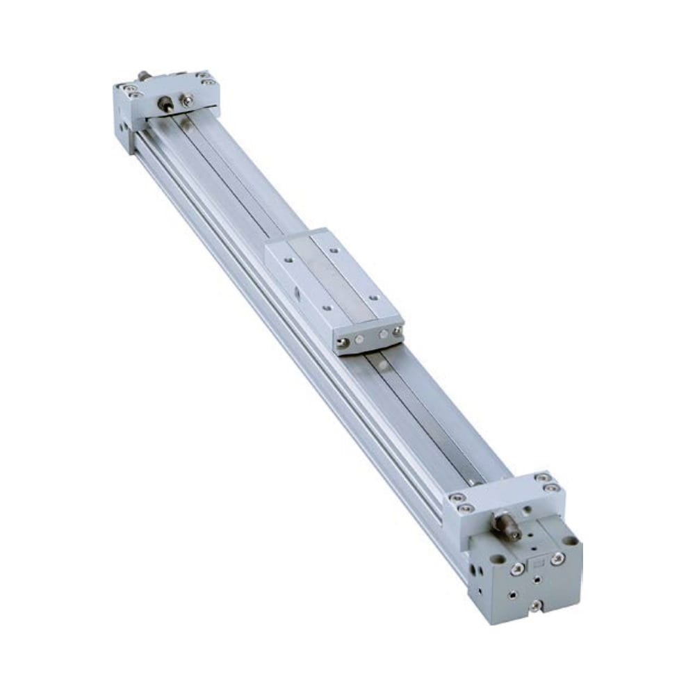
Rodless does not mean unlimited stroke, unlimited moment capacity, or no wear. Parker’s rodless selection literature requires evaluation of permissible loads, forces, moments, speed, and cushioning. Some machines still need an external guide because carriage moment capacity, payload offset, accuracy, or service-life requirements govern.
Choose architecture from the complete duty:
- travel and available installation envelope;
- axial force and pressure range;
- payload mass, center-of-gravity offset, and external moments;
- speed, cycle rate, and cushioning energy;
- positioning repeatability and rigidity;
- contamination, washdown, cleanroom, or corrosion requirements;
- maintenance access and expected service life.
ISO 15552 standardizes basic and mounting dimensions for interchangeability across specified bores and a 10 bar maximum rated pressure, but it does not publish one universal buckling capacity for every compliant cylinder (ISO 15552, confirmed 2025). Treat dimensional interchangeability and structural suitability as separate questions.
What Should a Design Review and Commissioning Checklist Include?
A defensible file links each calculation to the chosen product and machine state. SMC and Parker both rely on model- and mounting-specific tables rather than a universal stroke rule. Capture the assumptions early enough that purchasing, commissioning, and maintenance do not unknowingly change them (SMC, Parker, 2026).
Before release:
- record bore, rod diameter, stroke, product code, mounting code, and rod-end hardware;
- define normal, jam, hard-stop, gravity, and fault compression loads;
- draw the worst-extension geometry and dimension the actual unsupported length;
- document the end-restraint case used by the selected manufacturer’s method;
- run the Euler screen with units visible and state the source of and ;
- verify the result against the current manufacturer load/stroke chart;
- calculate guide loads, moments, bracket deflection, and cushioning energy separately;
- check pressure rating, speed, temperature, medium, environment, and duty cycle;
- review stored-energy and unexpected-motion hazards under the applicable machine safety process.
During commissioning, verify alignment through the entire stroke before applying full load. Record port pressures during the critical push if the margin depends on actual operating pressure. Inspect for binding, asymmetric seal contact, guide heating, abnormal noise, or visible lateral motion. Confirm that flow controls and cushions produce controlled deceleration without using the piston rod as a stop.
After maintenance, repeat the relevant checks when technicians change a rod-end adapter, bracket, mount, guide, regulator setting, payload, speed, or hard-stop location. Each change can alter compression force, effective length, alignment, or dynamic loading even when the cylinder part number stays the same.
Piston Rod Buckling FAQs
These answers cover the selection questions most likely to change a long-stroke design: hidden peak force, the difference between stroke and effective length, product-specific safety factors, the effect of a larger bore, and the limits of rodless alternatives. Keep each answer tied to the selected cylinder and machine geometry.
Can a pneumatic cylinder rod buckle with a light payload?
Yes. If the extended cylinder pushes against a fixed stop or jam, it may develop force near its maximum pressure-area thrust even though the normal payload is light. SMC explicitly uses maximum generated force in its buckling selection method. Evaluate credible stop, jam, gravity, and fault cases, not only routine process load.
Is cylinder stroke the same as buckling length?
Not necessarily. Buckling length depends on the physical unsupported length and the restraint supplied by both ends. Exposed rod, adapters, joints, and bracket flexibility can change it. Use the geometry and mounting case defined by the selected manufacturer’s procedure rather than entering nominal stroke as an unexplained substitute.
What safety factor should I use for piston rod buckling?
There is no universal value for every cylinder and machine. Parker recommends 3.5 to 5 in the cited P1F method, while Festo shows five in its referenced graph. Use the exact product procedure, duty uncertainty, dynamics, consequences, and applicable design requirements, then document the reason for the selected factor.
Will a larger cylinder bore prevent rod buckling?
Not automatically. A larger bore increases available thrust at the same pressure, which increases compression load. The associated cylinder may also have a larger rod, but both changes must be calculated and checked against the exact product chart. An oversized-rod option can sometimes increase stability without increasing bore-generated force.
Does a rodless cylinder eliminate every long-stroke problem?
No. It removes the long external rod as a compression column and may reduce installation length, but the carriage still has limits for force, payload, moment, speed, cushioning, and environment. Select the rodless product from its own load and moment data, adding external guidance when the complete duty requires it.