

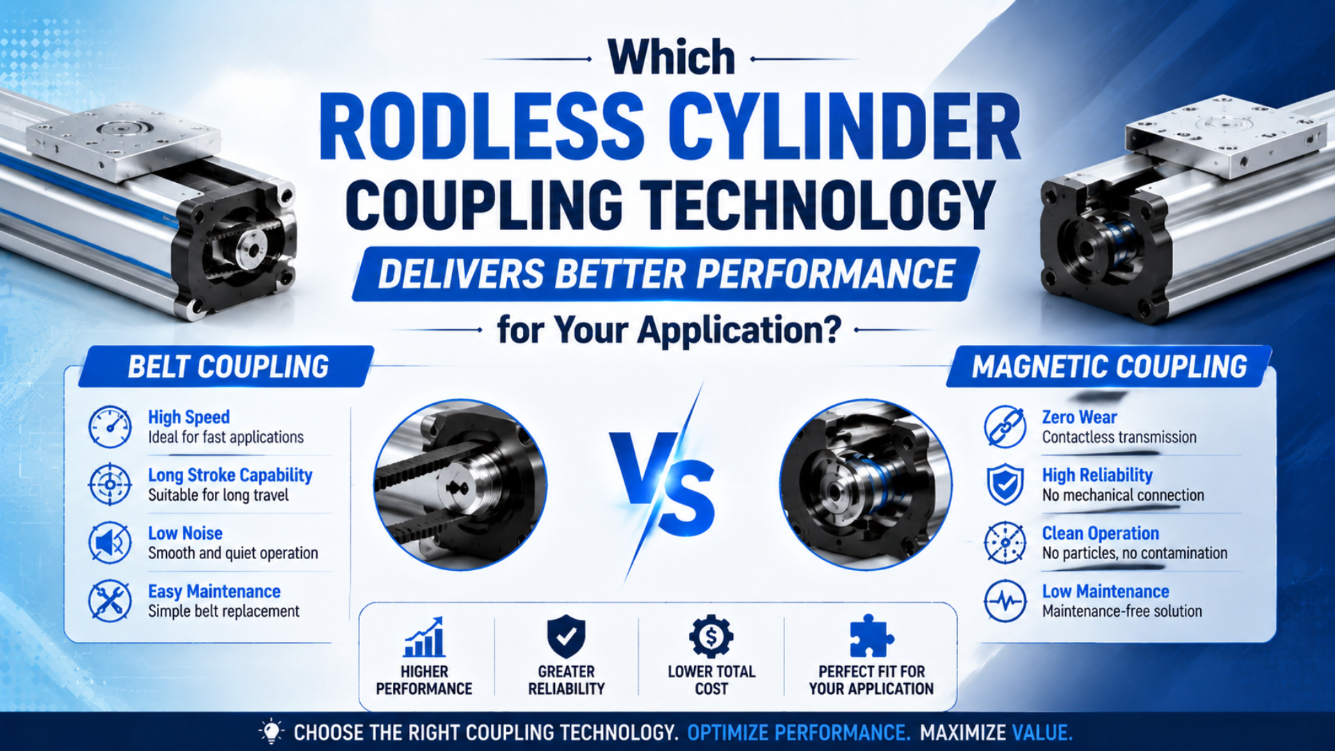
Neither rodless cylinder coupling technology is universally better. Magnetic coupling is often the stronger choice when a closed pressure tube, clean external geometry, and non-destructive decoupling matter. Mechanical coupling is usually better when the axis needs direct force transfer, broad guide options, or long-stroke modular construction.
The load case decides.
Published CY3B data lists magnetic holding forces from 19.6 N to 2,256 N across 6-63 mm bores. Parker’s OSP-P mechanical series lists actual output from 32 N to 2,600 N at 6 bar across 10-80 mm bores (SMC, 2024; Parker, 2025).
Those ranges overlap. A universal 500 N dividing line does not.
Key Takeaways
- Magnetic holding force is not carriage load.
- Published ranges overlap: SMC lists up to 2,256 N holding force, while Parker lists up to 2,600 N actual output at 6 bar.
- Check acceleration, orientation, guide moments, stopping energy, contamination, and service access before choosing a coupling.
How Do the Two Coupling Technologies Transfer Force?
Published SMC ranges show a 6-63 mm CY3B using magnets to move an external slider through a closed tube. The 10-100 mm MY1 family connects the piston mechanically through a sealed longitudinal slot (SMC CY3B, 2024; SMC MY1, 2026). That pressure-boundary difference drives most practical tradeoffs.
Magnetic coupling is a non-contact force-transfer method that links an internal piston to an external carriage through a closed, non-magnetic tube wall. Air pressure moves the piston, and magnetic attraction pulls the carriage without a slot running along the pressure chamber. Removing the slot does not make the actuator seal-free. It still has piston seals, end seals, wear rings, sliding surfaces, ports, and fittings. What disappears is the long slot-sealing system used by mechanically jointed cylinders. Depending on the load and environment, the external carriage may still need a guide, scraper, protective cover, or floating connection.
Mechanical coupling is a positive force-transfer method that connects the piston to the carriage through a slot in the cylinder profile. An inner band closes the pressurized chamber, while an outer band helps keep contamination away. Band condition and alignment therefore become part of routine inspection.
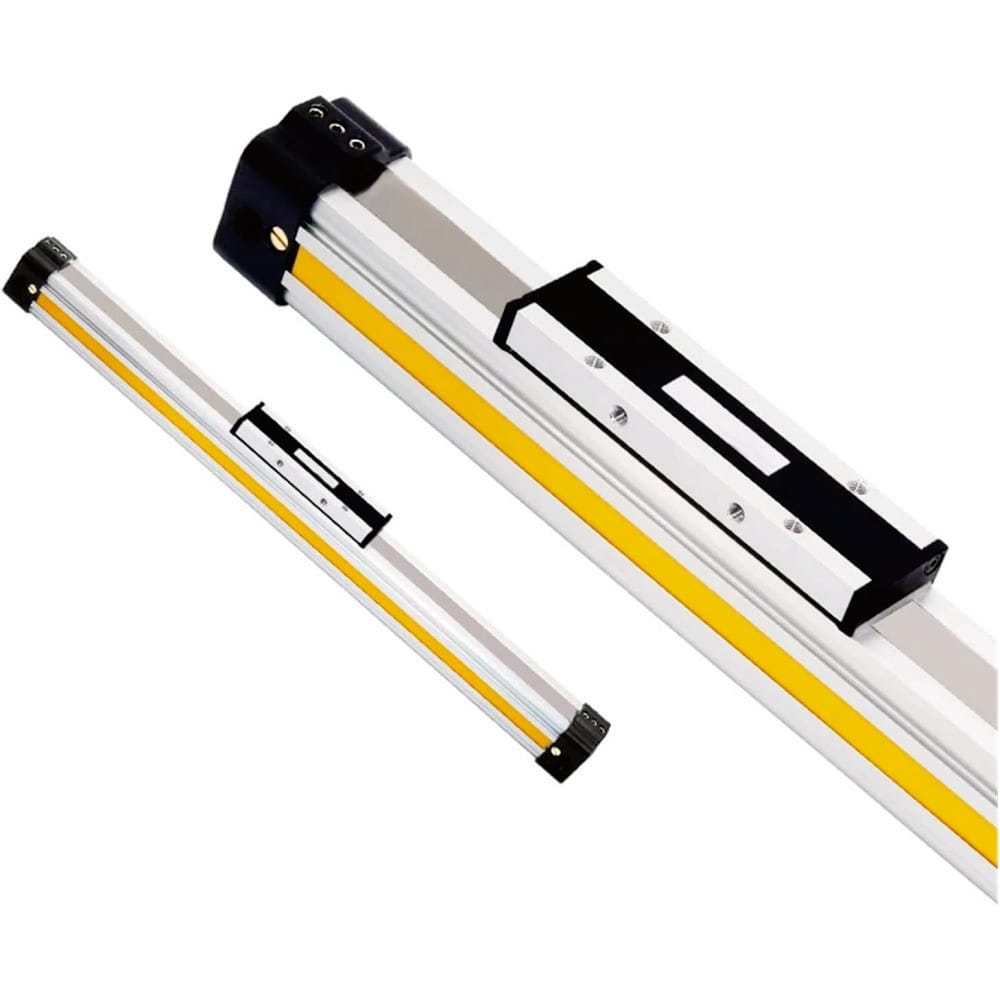
For a closer look at each mechanism, use the dedicated guides to magnetic rodless cylinders and rodless cylinder sealing bands.
Four Ratings Decide Performance
Parker evaluates OSP-P output force, total load, three moment directions, piston speed, and cushioning as separate limits. SMC likewise separates CY3B magnet holding force from allowable driving force and vertical load (Parker, 2025; SMC, 2024). One force number cannot prove that an axis is correctly sized.
One rating is never enough.
From our analysis of the SMC and Parker selection tables, we found that “force capacity” can refer to at least three different values: ideal piston thrust, transmitted carriage force, or permitted external load. Treating those values as interchangeable is the fastest route to an undersized coupling or overloaded guide.
Treat the selection as four gates. The axis passes only when every gate passes:
- Pneumatic force: pressure acting on piston area, less friction.
- Coupling or joint capacity: magnetic holding and allowable drive force, or the mechanical connection’s product limits.
- Guide capacity: allowable load plus pitching, rolling, and yawing moments.
- Stopping capacity: permitted kinetic energy for the air cushion, shock absorber, or external stop.
The theoretical pneumatic force starts with piston area:
Here, is piston area in square metres and is bore diameter in metres. With effective gauge pressure in pascals, the ideal piston force is:
is in newtons. It is not yet usable carriage force because seals, guides, tubing, pressure loss, acceleration, and the coupling mechanism add further limits. The Cylinder Force Calculator can check the pressure-area relationship, but final selection still needs the product catalog.
For a magnetic cylinder, the simpler design rule is:
must come from the chosen model’s holding-force or allowable-driving-force data. Apply the manufacturer’s load margin and vertical-operation rules after accounting for friction, acceleration, and external process force. A static magnetic holding value should never be presented as guaranteed dynamic output.
When Does Magnetic Coupling Win?
CY3B data from SMC lists 50-500 mm/s standard piston speed and magnetic holding force from 19.6 N to 2,256 N. Low-speed, heat-resistant, dust-seal, hard-chrome, and long-stroke variants are also available (SMC CY3B, 2024). Magnetic coupling wins when the closed tube solves a real problem without sacrificing load margin.
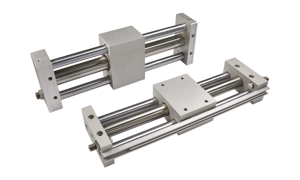
Choose a magnetic design first when these conditions line up:
- The pressure tube should have no longitudinal slot.
- Payload and acceleration sit well within the model’s coupling and drive limits.
- A jam may decouple, and the control system can detect and handle the resulting carriage-piston separation without creating a new hazard.
- Clean external geometry helps the process, with verified cleaning and material ratings available for the chosen model.
- Ferrous debris can be kept away.
Magnetic decoupling can act like an overload release, but it is not an automatic safety function. The internal piston may continue moving after the carriage slips. A vertical load can drop if the coupling detaches. SMC explicitly warns that a CY3B vertical load above the allowable value can separate the coupling and cause the load to fall.
Temperature deserves a product-level check, not a generic verdict. Standard CY3B data and made-to-order heat-resistant variants use different limits. Parker and other manufacturers also offer model-specific materials and temperature options. Ask for the complete actuator temperature rating, including magnets, seals, grease, sensors, guides, and protective parts. Magnetic coupling is also not automatically washdown-approved or cleanroom-certified. A closed tube helps, but fluid can still reach the carriage, guide surfaces, fasteners, ports, and sensors. Confirm corrosion resistance, cleaning-agent compatibility, lubrication behavior, scraper design, ingress protection, and any required cleanroom documentation.
When Is Mechanical Coupling Better?
Parker lists OSP-P bores from 10 to 80 mm, standard strokes up to 6,000 mm, and actual force up to 2,600 N at 6 bar. Selected long-stroke versions reach 41 m (Parker catalog, 2025). Mechanical coupling is the stronger starting point when direct transfer and modular guidance outweigh slot-seal maintenance.
Use a mechanically coupled design when the axis needs one or more of these features:
- Direct synchronization is mandatory.
- The application needs integrated linear guides, brakes, or shock absorbers.
- Stroke exceeds the practical magnetic family after tube-support and deflection checks.
- Maintenance teams need field access to inspect and replace sealing bands and wipers without removing the complete axis.
- Process force must remain synchronized through brief load changes, while output, guide, and cushion demands stay within their catalog ratings.
Direct connection does not mean unlimited force. The pressure and bore still set theoretical thrust, while the product construction sets actual output, guide loads, moments, speed, and cushion capacity. Parker’s OSP-P data, for example, lists 3,016 N theoretical output and 2,600 N actual output for the 80 mm basic cylinder at 6 bar. The seal band is a maintenance item, but a replacement interval cannot be predicted from coupling type alone. Life changes with alignment, contamination, speed, pressure, stopper impact, cleaning chemicals, and installation damage. Parker advertises service intervals up to 8,000 km for the OSP-P family, a product claim under specified conditions rather than a universal rule (Parker, 2026).
Mechanical designs can also serve clean or aggressive environments when the selected series includes the right bands, wipers, materials, and certified options. Parker offers cleanroom and ATEX OSP-P versions. That is why the environment column in a selection matrix must name the product option, not merely say “magnetic” or “mechanical.”
Guide Load, Side Force, and Positioning Accuracy
SMC’s MY1 selection method checks load mass, static moment, dynamic moment at stopper impact, and a summed guide-load factor no greater than 1.0. It also states that the basic MY1B does not guarantee travelling parallelism (SMC MY1B, 2024). Coupling style alone does not determine side-load capacity or positioning accuracy.
Guide moment is the turning effect created when a force acts away from the guide centreline. Coupling hardware moves the carriage, but the guide controls its orientation. An offset tool can create pitch, roll, or yaw even when its mass looks modest, and the moment rises with offset distance:
is moment in newton-metres, is the applied force in newtons, and is the perpendicular distance from the guide centreline in metres. Doubling the bracket offset doubles the moment without changing payload mass.
For Parker OSP-P, the catalog combines normalized load and moment terms into a load-moment factor. In simplified form for the ratings applicable to the chosen model:
is the external carriage load, while , , and are the applied moments. Use the exact equation and limits published for the selected guide version. Do not transfer values between basic, slide-bearing, roller-guide, and linear-guide configurations. Positioning also needs its own specification. Two-position repeatability at cushioned end stops is different from travel parallelism, intermediate positioning, or servo-like path control. If the process needs a precise intermediate stop, specify feedback, valve strategy, external stop, brake, or electric axis. “Mechanical coupling is more precise” is not a usable requirement.
For more examples of damaging load geometry, see the guide to side loading on linear actuators.
A Five-Step Selection Method
The MY1 selection flow reviews load mass, allowable moment, cushioning, port arrangement, and switch mounting before model selection. CY3B instructions add allowable driving force and vertical-operation limits (SMC MY1, 2015; SMC CY3B, 2024). A dependable comparison follows that order instead of scoring generic advantages.
Step 1: Calculate the real driving demand
Start with moving mass, target acceleration, mounting angle, guide friction, hose or cable drag, and external process force:
is moving mass in kilograms, is acceleration in metres per second squared, is gravitational acceleration, is the incline angle, is friction, and is any external pushing, clamping, or cutting force. Use worst-case pressure at the actuator during motion.
Step 2: Check the transfer mechanism
For magnetic coupling, compare demand with the manufacturer’s allowable drive and holding-force data for the exact bore and operating orientation. Check what happens after decoupling. For mechanical coupling, verify actual output and the joint’s product limits rather than assuming the piston can transmit every theoretical newton.
Step 3: Check the guide and mounting
Record payload centre of gravity, bracket offsets, mounting orientation, external guide arrangement, and stopper location. Calculate every applicable static and dynamic moment. A floating connection may be needed when a cylinder works alongside a separate linear rail, especially over a long stroke.
Step 4: Check speed and stopping energy
Cycle time affects acceleration force, valve flow, impact, and cushioning. SMC lists 50-500 mm/s for standard CY3B, while MY1 variants can reach different catalog speeds. The permitted load often falls as speed rises, so never compare “maximum speed” without the relevant load and cushion chart.
Step 5: Check environment and service access
ISO 8573-1 classifies compressed-air contaminants by particles, water, and oil (ISO, 2010). Add external hazards such as paper dust, metal chips, coolant, washdown chemicals, weld spatter, and ambient temperature. Then confirm how maintenance staff will inspect the carriage path, bands, guides, sensors, and end stops.
Failure behavior matters. If a jam should release without bending tooling, controlled magnetic decoupling may be useful. If the process cannot tolerate carriage-piston separation, a mechanical joint may be preferable, but its sealing and guide system must remain accessible.
| Application condition | Better starting point | Catalog checks that decide it |
|---|---|---|
| Closed pressure tube is required | Magnetic | Holding force, allowable drive, surface protection, certification |
| High direct driving demand | Mechanical | Actual force, pressure, joint limit, guide configuration |
| Offset or cantilevered load | Guided version of either type | Pitch, roll, yaw, dynamic moment, rail accuracy |
| Vertical lift | Neither by coupling alone | Drop prevention, allowable vertical load, brake or lock, risk assessment |
| Ferrous dust or grinding debris | Product-specific protected design | Scrapers, covers, magnetic debris attraction, cleaning access |
| Long stroke | Often mechanical or cable type | Tube support, deflection, guide alignment, cushion and flow |
| Cleanroom or washdown | Certified product option | Materials, lubrication, emissions, corrosion and cleaning compatibility |
The broader guide to rodless pneumatic cylinder types helps when cable-driven and guided slide designs are also being considered.
What Should You Send in the RFQ?
Across SMC’s range, CY3B has nine bore sizes from 6 to 63 mm and MY1B has ten from 10 to 100 mm. Bore and stroke alone cannot identify the correct coupling (SMC CY3B, 2026; SMC MY1, 2026). A useful RFQ must describe force path, guide load, environment, and failure requirement.
Send this information with the inquiry:
| RFQ field | Why it changes the selection |
|---|---|
| Current brand, model, bore, stroke, and photos | Identifies coupling, dimensions, ports, sensors, and interchange risk |
| Working pressure measured during motion | Establishes available pneumatic force under real flow demand |
| Moving mass and target stroke time | Sets force, acceleration, flow, and stopping energy |
| Load centre and bracket offsets | Reveals pitch, roll, and yaw moments |
| Mounting direction | Adds gravity and vertical-load constraints |
| External process force | Captures pushing, scraping, clamping, hose drag, and cable carriers |
| End-of-stroke method | Determines cushion, shock absorber, and stopper load |
| Environment | Screens dust, chips, washdown, chemicals, corrosion, and temperature |
| Required accuracy | Separates end-stop repeatability from travel and intermediate positioning |
| Acceptable failure mode | Establishes whether decoupling, leakage, or loss of synchronization is tolerable |
For a replacement, include photos of the nameplate, both end caps, carriage, full installed axis, guide arrangement, load bracket, and any damaged sealing band. A short video at slow speed can reveal whether drag follows one stroke position or changes with direction. Send the package through the contact page; the About Us page explains the engineering and manufacturing scope behind the review.
FAQs About Rodless Cylinder Coupling: Magnetic vs Mechanical
Published CY3B holding force reaches 2,256 N, while Parker lists OSP-P actual output up to 2,600 N at 6 bar. No universal force threshold separates the technologies (SMC, 2024; Parker, 2025). These answers keep the decision tied to catalog ratings and the installed load path.
What is the maximum force of a magnetically coupled rodless cylinder?
There is no universal 500 N maximum. SMC publishes CY3B magnetic holding forces from 19.6 N to 2,256 N across its bore range. Usable dynamic force can be lower because acceleration, friction, orientation, temperature, and product-specific allowable-driving-force rules consume margin. Check the exact model rather than a technology-wide threshold.
Are magnetically coupled rodless cylinders maintenance-free?
No pneumatic actuator is automatically maintenance-free. A magnetic design removes the long slotted sealing band, but piston seals, wear rings, carriage bearings, tube surfaces, ports, sensors, and guides still require suitable air quality and inspection. SMC’s CY3B documentation includes lubrication-retention and wear-ring features, confirming that sliding components remain part of the design.
Can a mechanically coupled cylinder carry more side load?
Not by coupling alone. Side load and pitch, roll, or yaw moment depend on the selected guide configuration. SMC offers five MY1 guide types and requires separate load-mass, static-moment, and dynamic-moment checks. A basic mechanical cylinder can still need an external guide or floating connection when the load is offset.
Which coupling is better for washdown or cleanroom service?
A closed magnetic tube can simplify the pressure boundary, but coupling type does not prove washdown or cleanroom suitability. Verify corrosion-resistant materials, external lubrication, scrapers, seals, cleaning-agent compatibility, sensors, ingress protection, and certification. Parker offers specific cleanroom OSP-P versions, showing that mechanical designs can also serve controlled environments.
What happens if a magnetic rodless cylinder decouples?
The internal piston can move without the external carriage until the magnet sets are synchronized again. SMC instructs users to restore an out-of-position coupling at the stroke end and warns that excessive vertical load can detach the coupling and let the load fall. Use guarding, sensing, and load-holding measures where separation creates risk.