

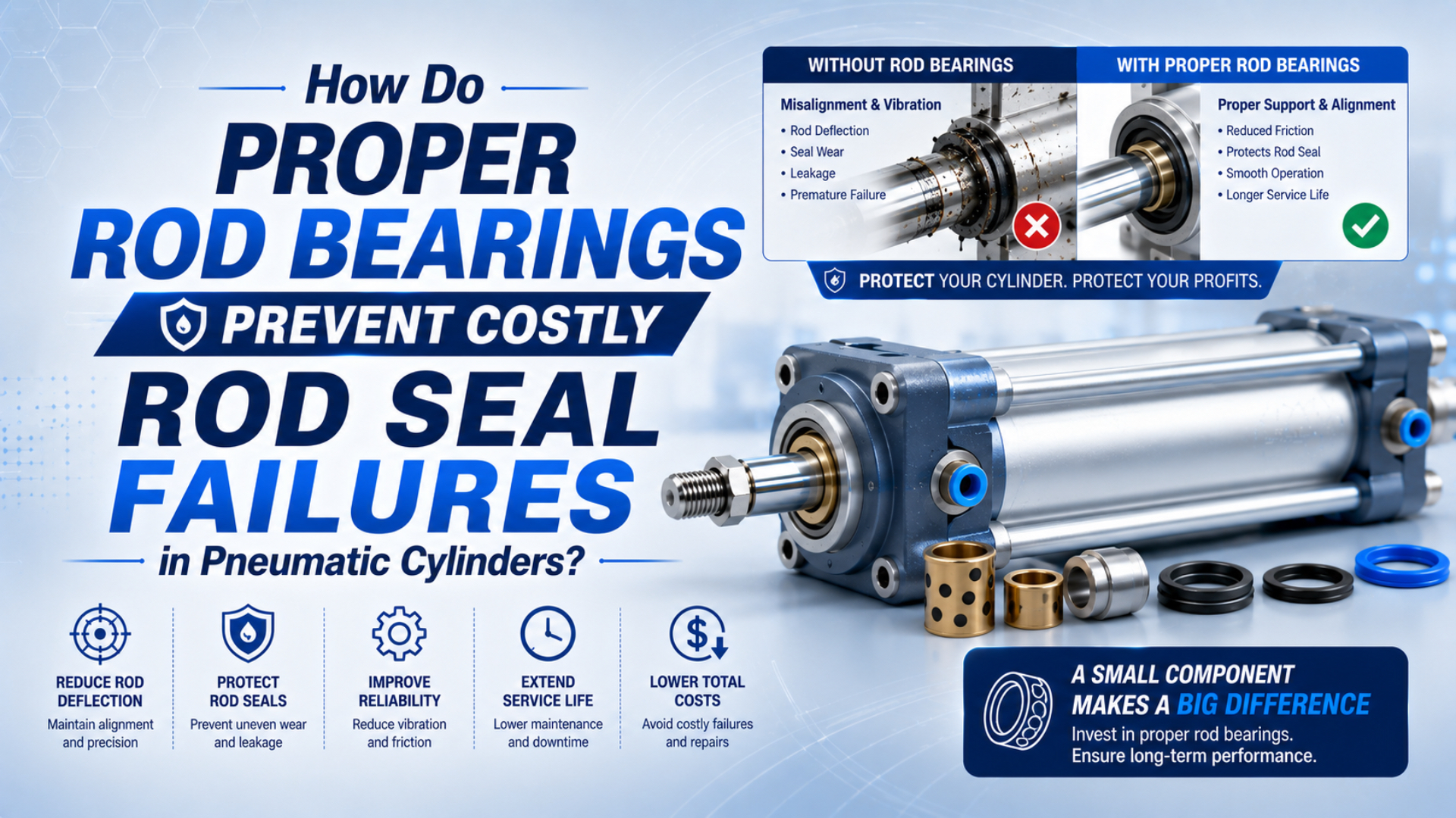
Proper rod bearings help a pneumatic cylinder rod seal survive by keeping the rod supported and centered within the clearance allowed by the cylinder design. They limit local contact between the rod, gland, and seal. They do not make a standard cylinder a linear guide, cancel mounting error, or provide a universal side-load rating. When the machine applies a significant transverse force or moment, an external guide or guided cylinder should carry that load.
This distinction matters because a new seal can stop leakage briefly while the damaged load path remains unchanged. One-sided lip wear, polished areas on one side of the rod, increased bushing clearance, and binding near full extension point to guidance or alignment problems. Treat those marks as evidence, then compare the actual geometry with the exact manufacturer’s load data.
Key Takeaways
- ISO 15552 covers interchangeable mounting dimensions for 32-320 mm cylinders, not allowable side load.
- The rod bearing guides the rod; the rod seal retains pressure; the wiper excludes dirt.
- Repeated one-sided seal wear calls for alignment, clearance, and external-guidance checks before another seal replacement.
What Does a Pneumatic Cylinder Rod Bearing Actually Do?
ISO 15552 applies to cylinders with 32-320 mm bores and a maximum rated pressure of 1,000 kPa, but its scope is dimensional interchangeability, not rod-bearing capacity (ISO 15552:2018, confirmed 2025). A rod bearing therefore has to be understood from the selected cylinder’s construction and catalog, not from the ISO envelope alone.
A rod bearing is the sleeve or bushing in the head or gland that supports the sliding rod. It maintains radial support, prevents direct contact between the rod and housing under permitted conditions, and helps the rod pass through the pressure seal on the intended axis. Material, length, clearance, lubrication method, and distance from the piston all affect its behavior.
The surrounding parts perform different jobs:
| Component | Primary function | What it does not prove |
|---|---|---|
| Rod bearing or guide bushing | Supports and guides the sliding rod within specified clearance | That the cylinder can act as an unsupported linear rail |
| Rod pressure seal | Retains compressed air at the moving rod interface | That it can guide a misaligned rod |
| Rod wiper or scraper | Limits entry of external dust, chips, and moisture | That it is a pressure seal or a structural bearing |
| Piston wear ring or guide | Keeps the piston from rubbing directly on the bore | That the extended rod can accept any side load |
| External guide or guided carriage | Carries specified lateral forces and moments | That cylinder mounting alignment can be ignored |
Parker describes its A2 rod wiper as a part that prevents dust, dirt, sand, and swarf from entering the dynamic rod guide (Parker A2 Wiper Seal, accessed 2026). That is a contamination-control function. Calling the rod bearing itself a contamination barrier blurs the diagnosis and can send maintenance teams toward the wrong replacement part.
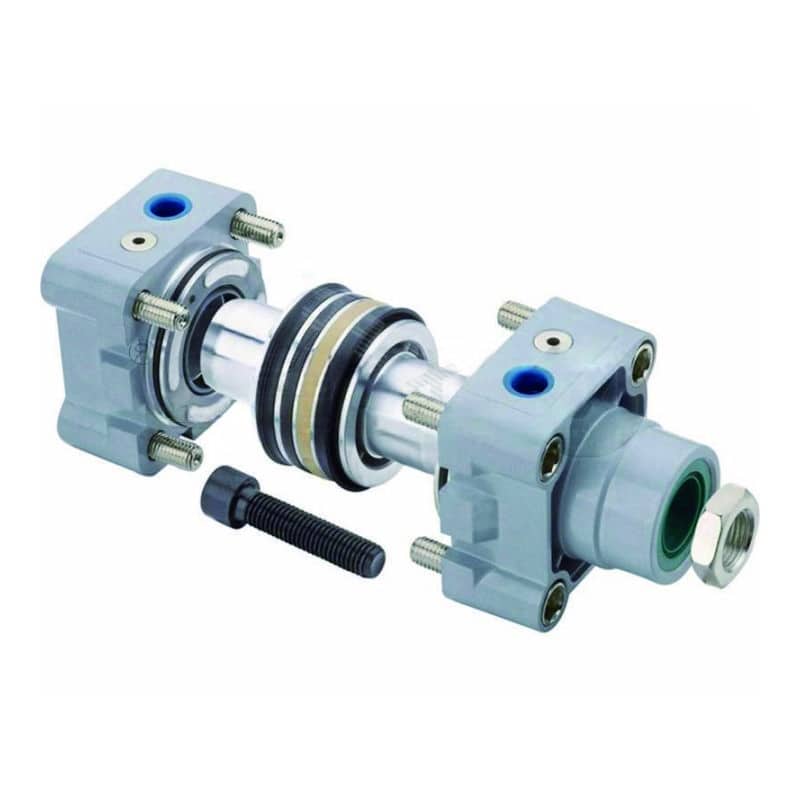
An exploded ISO-profile cylinder helps identify the rod-end guide, rod seal, piston guidance, and other repair components. Their exact arrangement and allowable loads remain model-specific.
The useful question is not whether the cylinder “has a bearing.” Nearly every conventional rod cylinder needs some form of rod guidance. Ask whether the bearing length, clearance, rod extension, load offset, and external guide arrangement match the real load path. That turns a vague component claim into a checkable engineering decision.
For a broader comparison of pressure seals, wipers, piston seals, and cushioning seals, see the guide to industrial cylinder seal types.
Why Does Side Load Damage Rod Seals and Bushings?
SMC’s C96 cylinder manual presents allowable lateral load as a curve that changes with stroke, then warns that exceeding the curve can damage the bearing, piston seal, or piston (SMC C96 Manual, 2024). There is no defensible single newton value for every rod bearing, bore, stroke, or mounting geometry.
Side load is force applied across the cylinder’s intended stroke axis. It pushes the rod against one side of the guide bushing. If the load acts at an offset from the support, the offset also creates a bending moment. For example, a cylinder may move smoothly near retraction yet bind or leak near full extension as the unsupported lever arm grows.
That biased rod position changes how the seal lip contacts the surface. Contact pressure rises on one side and falls on the other. The bushing may polish or wear unevenly, the rod may develop longitudinal scoring, and particles can be dragged repeatedly through the same loaded sector of the seal. Once clearance grows, the rod can move farther off axis, accelerating the cycle.
Misalignment can create the same symptoms even when the external payload seems light. A rigid clevis, bracket, or tool plate can force the rod to follow a path that differs from the cylinder centerline. Frame deflection under production load may create an error that cannot be seen during an unloaded hand check. Raising air pressure only adds axial force; it does not correct the geometry.
SMC also warns that misalignment between a rod and the load can damage the tube, bushing, rod surface, and seals, and recommends a floating joint where appropriate (SMC Cylinder Safety Instructions, accessed 2026). A floating joint accommodates small connection error. It does not carry a large transverse force, overturning moment, or unsupported payload.
If you need the broader mechanics of force direction, offset, and moment, use the dedicated explanation of side loading on linear actuators. This article stays with the bearing-to-seal failure path.
Which Component Should Carry the Machine Load?
Parker offers external guide modules for P1D cylinders with 32-100 mm bores and standard guided strokes from 25-250 mm, using either plain or linear-ball-bearing guidance (Parker P1D Catalog, accessed 2026). Those product-specific ranges show why guidance should be selected as hardware, not assumed from a generic cylinder label.
An external guide is a separate rail, slide, or guided carriage that carries specified lateral load and moment while the standard cylinder creates axial thrust. Parker’s application guide is direct on this point: an external guide should keep the driven load aligned with the cylinder centerline, while centerline mounting minimizes loads on the piston and rod bearings (Parker Application Engineering Guide, accessed 2026).
Which arrangement fits the machine?
| Machine condition | Preferred load path | Check before release |
|---|---|---|
| Load already runs on a linear rail | Cylinder supplies thrust through an aligned or floating connection | Rail resistance, parallelism, coupling freedom, hard-stop location |
| Tooling must resist rotation | Guided cylinder or separate anti-rotation guide | Rated moments in every axis, stroke, speed, center-of-gravity offset |
| Horizontal rod supports an overhung tool | External guide or supported carriage | Gravity force and moment at maximum extension |
| Small assembly tolerance remains | Model-approved floating joint plus independent guidance | Joint articulation, thread engagement, clearance through full stroke |
| Load pivots through an arc | Pivot mounts and joint geometry matched to the arc | Angular travel, hose movement, end-position binding |
| No lateral-load data is available | Obtain configured data or redesign so a guide carries the load | Do not invent a percentage of cylinder thrust |
Festo explains that guided drives combine pneumatic motion with two guide rods using slide or ball bearings, allowing the assembly to address lateral force and torque that a standard rod cylinder is not meant to control alone (Festo Guided Drives White Paper, accessed 2026). Even then, capacity depends on guide type, stroke, speed, load position, and moment direction.
A larger cylinder bore may increase axial force while leaving the side-load problem untouched. Sometimes it makes the symptom less obvious because the cylinder can push through higher friction. Separate the force calculation from the guidance calculation, then verify both against the configured product data.
The step-by-step selection logic in how to mitigate linear-cylinder side loads covers guide moments and retrofit choices in more detail.
Wear Patterns Reveal the Real Failure Path
Parker rates its A2 wiper for zero pressure and speeds up to 2 m/s, a product-specific example that separates dirt exclusion from pressure retention (Parker A2 Wiper Seal, accessed 2026). When leakage appears, inspect the wiper, rod seal, rod surface, and guide bushing separately instead of labeling the entire gland “the seal.”
Start with the direction of the evidence. A uniformly worn lip can point toward normal service wear, unsuitable material, poor lubrication conditions, temperature, or contamination. Wear concentrated on one side is more consistent with a biased rod path. For example, matching the seal’s worn clock position to bushing polishing and rod scoring can reveal the direction of the external reaction.
| Observation | Likely branches | Verification step |
|---|---|---|
| Rod seal lip worn mainly on one side | Misalignment, side force, worn bushing, bent or scored rod | Mark the wear clock position; compare it with load direction and bushing contact |
| Long axial scratches on the rod | Abrasive contamination, damaged wiper, biased bearing contact | Clean the rod; inspect scratch depth, wiper lip, bushing, and contamination source |
| Leakage returns soon after a seal change | Root alignment or surface damage was not corrected | Check rod finish, runout, bushing clearance, mounts, guide movement, and tube condition |
| Motion binds near full extension | Growing lever arm, guide misalignment, structure deflection | Compare unloaded and loaded motion at retracted, mid-stroke, and extended positions |
| Rod can be rocked visibly at the gland | Worn guide bushing or damaged head | Measure clearance using the manufacturer’s procedure and limits |
| Seal looks sound but air bypasses internally | Piston seal, tube, or valve leakage rather than rod-seal leakage | Isolate the circuit under an approved procedure and locate the leakage path |
A repeat rod-seal leak should be treated as a load-path investigation, not automatic proof that the replacement seal was poor. SMC links excessive lateral load and misalignment with bearing friction, rod-surface damage, seal damage, and air leakage, while Parker assigns external dirt exclusion to the wiper rather than the bearing (SMC; Parker, accessed 2026). Read those facts together: inspect the installed direction of wear, compare rod and guide alignment through the complete stroke, measure bushing clearance and rod condition against the exact service limits, and confirm which component carries lateral force. If the new seal is installed before those checks, it may only reset the visible symptom. If the guide, mount, rod surface, and clearance pass, then material compatibility, lubrication, temperature, tube condition, and pressure-seal installation move higher on the fault tree.
Don’t condemn the rod bearing from a leakage symptom alone. The pneumatic cylinder fault-troubleshooting workflow helps separate supply, valve, exhaust, guidance, load, and internal-seal branches. If contamination or chemical exposure is present, compare the evidence with the self-lubricating seal limitations guide.
In our experience, the fastest useful inspection is a directional one: photograph the seal and bushing before cleaning, mark the cylinder’s installed orientation, and record where binding occurs in the stroke. Those three observations often preserve evidence that disappears once parts are washed and placed loose on a bench.
How Should Engineers Correct and Verify the Installation?
ISO 19973-3 reports pneumatic-cylinder reliability in cycles or kilometres and uses first-failure testing with defined thresholds (ISO 19973-3:2015, confirmed 2021). That framework is why an unsupported promise of “three times longer seal life” is not a substitute for a defined configuration, duty, environment, failure criterion, and test record.
First, follow the machine’s energy-control procedure. Isolate pneumatic and other energy sources, secure suspended or moving loads, release trapped pressure, and verify the safe state before loosening a cylinder, guide, joint, or fitting. Observation during an energized cycle and hands-on service are different activities and should be controlled accordingly.
Then use a correction sequence that protects the evidence:
- Record the failure condition. Note stroke position, direction, payload, speed, temperature, pressure during motion, and whether the fault occurs only after warm-up. Save the last known good cycle data when it exists.
- Inspect before cleaning. Photograph the rod, wiper, pressure seal, bearing surface, piston guidance, and lubricant or debris. Preserve the installed clock position.
- Check the load path. Compare cylinder and guide centerlines at retracted, mid-stroke, and extended positions, both unloaded and under representative load. Repeat the check after the frame and tooling reach operating temperature.
- Measure the damaged parts. Use the manufacturer’s limits for rod straightness or runout, surface condition, bushing clearance, bore damage, seal groove condition, and fastener integrity.
- Correct guidance and connection geometry. Realign mounts, remove unintended constraint, add a suitable floating connection, or specify an external guide or guided cylinder using the real force and moments. Confirm that hard stops act through the supported structure rather than the rod.
- Replace only compatible parts. Match the service kit to the exact cylinder series, bore, rod diameter, material option, temperature, lubricant, and environment.
- Verify progressively. Confirm free movement and alignment first, then run at reduced energy if the approved commissioning procedure allows it, and finally validate representative load, speed, stroke, cushioning, leakage, and repeatability.
Should the bearing and seal always be replaced together? No. Replace each part that is outside its specified condition, and correct the cause. A worn bushing can quickly damage a new rod seal, while a cut seal does not automatically prove that the bearing is unserviceable. The rod surface and head or gland may also decide whether a service kit is enough.
When scoring, deep scratches, a bent rod, damaged gland bore, or unavailable dimensional limits make repair uncertain, compare the risk with the repair-versus-replace decision framework. For an RFQ, provide the cylinder model, bore, stroke, rod diameter, mount, guide arrangement, load mass and center of gravity, speed, cycle rate, air quality, environment, failure photographs, and measured clearances.
Pneumatic Cylinder Rod Bearing FAQs
ISO 15552 defines dimensions for 32-320 mm cylinders, while ISO 19973-3 measures reliability in cycles or kilometres; neither supplies a universal rod-bearing side-load or seal-life value. The answers below keep component function, configured load data, and failure evidence separate so the FAQ can be used as a practical maintenance screen.
Is a rod bearing the same as a rod seal?
No. The rod bearing or guide bushing supports the sliding rod, while the rod pressure seal retains compressed air. A separate wiper limits entry of external dirt. Parker’s A2 wiper is specified at zero pressure, which illustrates why wiper, seal, and bearing functions should not be treated as one component (Parker, accessed 2026).
Can a standard pneumatic cylinder carry side load?
Only within the exact manufacturer’s configured limit. SMC’s C96 manual uses a stroke-dependent lateral-load curve rather than one universal newton value. If load, offset, stroke, speed, or mounting falls outside the stated conditions, use a separate guide or guided cylinder instead of estimating capacity as a percentage of axial thrust (SMC, 2024).
When is an external guide required?
Use an external guide when the machine must carry meaningful transverse force, overhung weight, rotation, or moment that the selected cylinder does not explicitly permit. Parker’s P1D guide modules cover configured 32-100 mm cylinders, proving that guide selection depends on bore, stroke, bearing type, and geometry rather than the word “bearing” alone (Parker, accessed 2026).
Can a floating joint fix every alignment problem?
No. A floating joint can accommodate limited connection misalignment, but it does not become a rail or carry every lateral force and moment. SMC recommends such a joint where suitable and separately advises external guidance for excessive lateral load. Verify joint articulation, guide datum, load offset, and full-stroke freedom against the exact component instructions (SMC, accessed 2026).
Should the rod bearing and rod seal be replaced together?
Replace both only when inspection shows both are damaged, outside dimensional limits, or included in the approved service procedure. ISO 19973-3 defines cylinder life through a stated first-failure test, not a fixed replacement interval. A new seal will fail again if excessive bushing clearance, rod scoring, misalignment, or external side load remains (ISO, confirmed 2021).
Sources and technical references
- ISO 15552:2018, Pneumatic fluid power cylinders, scope and dimensional interchangeability; confirmed 2025, retrieved 2026-07-18.
- ISO 19973-3:2015, Reliability assessment by testing, Part 3: Cylinders with piston rod, cycles or kilometres and first-failure method; confirmed 2021, retrieved 2026-07-18.
- Parker Application Engineering Guide, centerline alignment and external guidance; retrieved 2026-07-18.
- Parker P1D Pneumatic Cylinder Catalog, external guide modules and floating connection; retrieved 2026-07-18.
- Parker A2 Wiper Seal, wiper function and product ratings; retrieved 2026-07-18.
- Festo, Considerations for Choosing Pneumatic Guided Drives and Slides, guided-drive architecture; retrieved 2026-07-18.
- SMC C96 Cylinder Manual, stroke-dependent lateral load and external guide warning; retrieved 2026-07-18.
- SMC Cylinder Safety Instructions, misalignment, floating joints, and external guidance; retrieved 2026-07-18.