

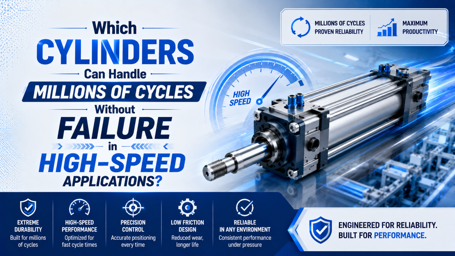
High-cycle pneumatic cylinders cannot be selected from a construction label alone. No cylinder type can promise millions of cycles without failure merely because it is described as high-speed, guided, compact, ISO, or rodless. A credible candidate needs model-specific endurance evidence tied to load, stroke, speed, pressure, environment, maintenance, and a defined failure limit. Parker’s P5T guided thruster is one documented example: its load diagrams are based on a service life of at least 10 million cycles, and Parker warns that higher loads reduce life (Parker P5T, 2025). That does not make every P5T configuration suitable for every fast machine. Nor does it establish a universal ranking. Define the production exposure, shortlist exact models with relevant evidence, compare their test conditions with the machine, and validate the complete actuator system before release.
Key Takeaways
- Parker bases P5T load diagrams on at least 10 million cycles within stated loads.
- Speed or frequency ratings do not establish service life.
- ISO 19973-3 expresses cylinder life in cycles or kilometres.
- A B10 value is statistical, not a failure-free guarantee.
- Count both cycles and accumulated travel before approving a model.
The useful question is not “Which cylinder lasts longest?” It is “Which exact cylinder has endurance evidence that still applies after the real load, stroke, speed, stop, air quality, and failure criteria are substituted?” That change turns a marketing comparison into a qualification task.
What Does “Millions of Cycles” Actually Prove?
ISO 19973-3 states that pneumatic-cylinder lifetime is normally expressed in cycles or kilometres and defines test procedures for cylinders with piston rods. The methods address first failure under stated conditions, not an unconditional promise that every cylinder will reach the reported number (ISO 19973-3, 2015).
A cycle is one complete sequence defined by the test or machine specification. For a double-acting cylinder, teams commonly mean extend and retract, but a supplier may count strokes, reversals, or machine operations differently. Define the event before comparing numbers.
A failure criterion is the measurable limit that ends the test. It might be external leakage, internal bypass, increased breakaway pressure, incomplete stroke, cycle-time drift, excessive guide play, damaged cushioning, or another specified loss of function. “Still moving” is not a sufficient pass condition.
Ask five questions whenever a brochure says “10 million cycles”:
- Was the figure a tested value, a statistical B10 value, a design basis, or an estimate?
- Which exact model, bore, stroke, mounting, seal option, and guide version were tested?
- What pressure, speed, load, frequency, air quality, temperature, and lubrication were used?
- How many specimens were tested, and how were outliers and repairs handled?
- What threshold counted as the first failure?
Without those answers, the number cannot be transferred safely to a production line.
From our analysis of ISO 19973 and Festo’s service-life guidance, a complete million-cycle statement needs four layers: an exposure measure, a failure threshold, a test population, and declared conditions. Cycles or kilometres quantify exposure. Leakage, timing, pressure, play, or damage defines failure. Sample results and statistical treatment describe the population. Pressure, stroke, speed, load, air quality, temperature, and maintenance define where the result applies. Remove any layer and the claim becomes ambiguous. For example, a unit can finish 10 million unloaded bench cycles yet fail a production acceptance limit much earlier because guide play or stroke time has already drifted beyond the machine requirement. That is why service-life evidence must describe both how far the test ran and what “passed” meant at the end.
High-Cycle Pneumatic Cylinders With Documented Million-Cycle Evidence
Parker publishes a concrete 10-million-cycle design basis for the P5T short-stroke thruster’s load diagrams. By contrast, SMC publishes up to 2,500 mm/s and 15 Hz for its CM2/CQ2-X3423 high-speed series, but those speed and frequency values are not a stated 10-million-cycle life rating (Parker P5T, 2025; SMC CM2/CQ2-X3423, 2026).
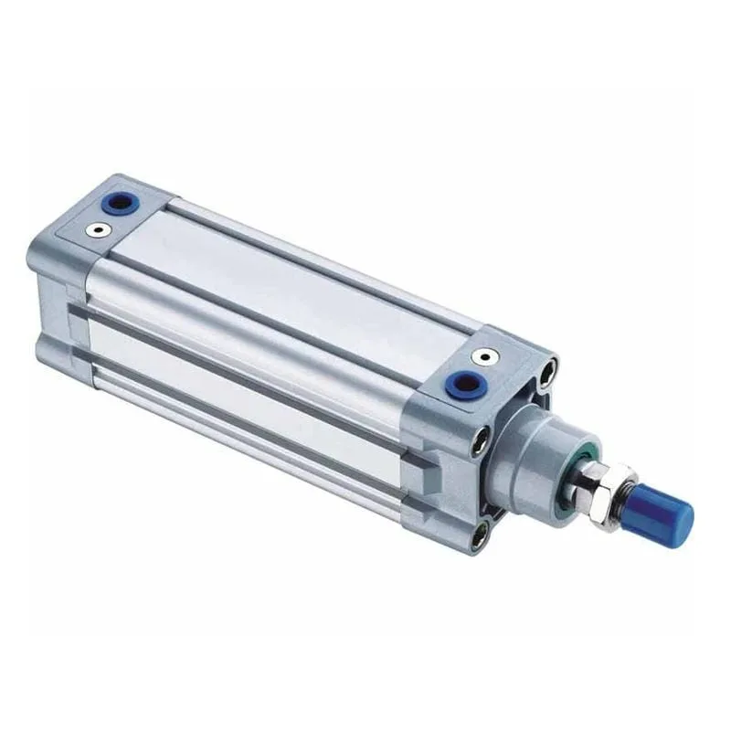
The evidence is more important than the category name:
| Candidate design | What published evidence can establish | What it does not establish |
|---|---|---|
| Guided short-stroke thruster | Parker P5T load diagrams use a service-life basis of at least 10 million cycles within the plotted load and geometry | Suitability above the load curve, at an unlisted speed, or with a different stop and environment |
| High-speed or high-frequency piston-rod cylinder | SMC CM2-X3423 reaches 12 Hz at 25 mm stroke; CQ2-X3423 reaches 15 Hz at 5 mm stroke; both list up to 2,500 mm/s | A minimum number of cycles before failure or approval at another stroke and circuit |
| Standard ISO 6432, ISO 15552, or ISO 21287 cylinder | ISO 19973-3 supplies a reliability-test framework for applicable piston-rod cylinders | A universal service-life value for every compliant cylinder |
| Guided, compact, or anti-rotation cylinder | Model-specific load, moment, bearing, speed, and endurance data may support a high-cycle target | An automatic life advantage from the construction label alone |
| Rodless cylinder | A manufacturer test or application-specific qualification can support the exact design and load path | Direct coverage by ISO 19973-3, whose stated scope is cylinders with piston rods |
This distinction prevents a common selection error. A cylinder can have an excellent frequency rating but no public endurance value. Another can have a 10-million-cycle load basis but be too slow, too lightly cushioned, or geometrically unsuitable for the machine.
We found that published cylinder evidence falls into three distinct classes. Parker’s P5T material links a load diagram to at least 10 million cycles, so it supports a conditioned life statement for that guided short-stroke family. SMC’s CM2/CQ2-X3423 material publishes 12 Hz, 15 Hz, and 2,500 mm/s limits, so it supports a conditioned speed and frequency statement, not a minimum life. ISO 19973-3 supplies a repeatable reliability framework for applicable piston-rod cylinders, but it does not assign one service life to every compliant design. These classes cannot be combined into a generic ranking. A useful shortlist must show which exact requirement each document proves and which requirements still need supplier confirmation or a representative application test.
For the complete speed, flow, load, and RFQ process, use the high-speed pneumatic cylinder specification checklist. This article stays focused on endurance evidence.
Why Is a B10 Value Not a Failure-Free Guarantee?
Festo defines B10 as the cycle count at which 10% of tested components have exceeded defined limits under specified conditions (Festo Product Service Life, 2013). It also states that a component can fail before B10 and that service life cannot be guaranteed.
B10 is a statistical reliability characteristic, not a minimum guaranteed life for every unit. If B10 is 10 million cycles, the definition does not mean that all units survive 10 million cycles. It describes a population and a defined test threshold (Festo Product Service Life, 2013).
Three labels must remain separate:
- Test completion: one or more samples reached a stated count under stated conditions.
- B10 or another statistical value: a population characteristic calculated from a test method and failure data.
- Warranty or application guarantee: a commercial commitment with explicit scope, exclusions, and remedies.
ISO 19973-1 notes that component lives vary and calls for statistical evaluation to interpret results. Its method applies to first failure without repair, while excluding outliers under its stated method (ISO 19973-1, 2015). ISO/TR 16194 adds guidance for accelerated testing but does not provide one universal acceleration procedure because methods vary (ISO/TR 16194, 2017).
So what should a buyer request? Ask for the reliability term, test method, sample size, confidence treatment, failure thresholds, outlier policy, and full operating conditions. “Tested to 10 million” without those details is an observation, not a complete reliability claim.
Cycle count is an odometer, not a warranty. It records exposure. Reliability requires a population, defined limits, and conditions; warranty requires a separate written commitment.
How Do You Convert Production Rate Into a Qualification Target?
At 180 cycles per minute, 16 operating hours per day, and 250 days per year, an actuator completes 43.2 million machine cycles annually. That arithmetic defines the exposure target, not the expected cylinder life. It must be paired with stroke distance and exact cycle definition before comparison with test evidence.
Annual cycles are:
where is cycles per year, is cycles per minute, is operating hours per day, and is operating days per year. The formula assumes the stated frequency is sustained throughout the operating hours. Subtract planned stops, changeovers, and non-cycling dwell if they are not already excluded.
For the 180-cycle example:
Now calculate sliding distance. For a double-acting cylinder completing one extension and one retraction per cycle:
where is accumulated travel in metres and is stroke in metres. A 50 mm stroke at 43.2 million cycles travels 4,320 km per year. A 500 mm stroke at the same frequency would travel ten times farther, even though both applications report the same cycle count.
This is why ISO 19973-3 recognizes both cycles and kilometres. The separate pneumatic duty-profile guide explains how to record motion, dwell, frequency, and accumulated travel across a complete production sequence.
Why Can High Speed Shorten Life Even When Frequency Is Allowed?
SMC warns that continuous high-speed, high-frequency operation can heat the cylinder tube and that end-of-stroke impact increases with speed. Its catalog requires the operating speed and load mass to remain inside the allowable kinetic-energy range and notes that the pneumatic circuit can prevent rated high-frequency operation (SMC CM2/CQ2-X3423 Catalog, 2026).
Frequency, piston speed, and accumulated travel describe different exposures:
- Frequency counts how often the sequence repeats.
- Speed determines how quickly the moving mass travels and enters cushioning.
- Travel accumulates sliding distance at seals, guides, and bearings.
- Stopping energy loads cushions, end caps, mounts, tooling, and shock absorbers.
- Reversal changes seal direction, guide reaction, pressure, and acceleration.
At constant moving mass, kinetic energy is proportional to the square of speed. Doubling speed produces four times the kinetic energy before adding cylinder thrust through the stopping distance. A frequency rating cannot override the model’s allowable energy or mass-speed diagram.
Parker also notes that piston speed at cushion entry can be about 50% above average stroke speed. That higher value, not the simple stroke-length divided by stroke-time average, is used for cushion selection (Parker P1F, 2025).
Use the high-speed air-cushion guide when stop energy or rebound controls the design. It includes the dedicated cushion-energy workflow; this article does not use that calculator as a life predictor.
Test Conditions That Must Match the Real Machine
ISO 19973-1 requires stated test conditions and statistical data evaluation because component life varies. ISO 19973-3 adds cylinder-specific equipment, thresholds, and reporting. A cycle value should therefore be transferred only after the production conditions have been compared with the tested configuration (ISO 19973-1, 2015; ISO 19973-3, 2015).
Build a side-by-side qualification sheet:
| Variable | Supplier evidence | Production requirement | Decision question |
|---|---|---|---|
| Model and size | Full part number, bore, stroke, options | Ordered configuration | Is the tested construction identical? |
| Cycle definition | Stroke, reversal, or extend-retract pair | PLC and machine definition | Are both sides counting the same event? |
| Load | Axial force, mass, side load, moments | Tooling, product, cable and hose forces | Is every reaction inside the tested or published limit? |
| Motion | Frequency, average and peak speed, acceleration | Peak and sustained recipe | Does the test cover the real motion profile? |
| Stop | Cushion, bumper, shock absorber, external stop | Actual stop architecture | Is energy absorbed by the same components? |
| Air | Pressure, dynamic pressure, filtration, water, oil | Point-of-use measurements | Does air quality and pressure remain comparable? |
| Environment | Temperature, chemicals, particles, washdown | Worst operating and cleaning condition | Are seals, grease, coatings, and sensors compatible? |
| Maintenance | Inspection, lubrication, adjustment, replaced parts | Site maintenance plan | Was the test continuous, serviced, or repaired? |
| Failure threshold | Leakage, pressure, timing, play, damage | Machine acceptance limit | Would the supplier’s passing unit still meet production needs? |
| Statistical basis | Sample size, failures, outliers, confidence method | Required reliability target | Is the reported number a valid population measure? |
For example, a short-stroke guided thruster qualified inside its load diagram should not be approved for a long-stroke side-loaded linkage. A high-frequency compact cylinder tested at 5 mm stroke should not be assumed to retain the same frequency at 200 mm stroke. The product names may sound suitable while the conditions do not match.
Our team found that stroke, load geometry, and stop architecture are the most easily lost conditions when teams compare catalogs. A short test stroke reduces accumulated travel per cycle and can change the time available for acceleration and cushioning. A centered axial mass does not reproduce an offset tool that creates guide moments. A test rig with an external shock absorber does not prove that the cylinder’s internal cushion can stop the same payload. Air-path details matter too. Valve response, tube volume, fittings, exhaust restriction, and dynamic port pressure determine whether the piston reaches the published speed and how hard it enters the stop. Keep these conditions visible in one comparison sheet so a matching cycle count does not conceal a different mechanical test.
Air quality, alignment, and surface condition also matter. Use the pneumatic actuator maintenance checklist for condition records and the side-loading guide when the load center is offset from the motion axis.
What Evidence Should a Supplier Provide?
Parker’s P5T statement ties life to a load diagram and warns that greater loading reduces it. That is the minimum standard for a useful catalog claim: the cycle number must connect to the variables that govern it. An unsupported “premium seal” or “reinforced construction” description cannot replace test evidence (Parker P5T, 2025).
Our source comparison found that the strongest evidence answers both transfer and traceability questions. Transfer asks whether the tested bore, stroke, load, speed, stop, air, and environment represent the ordered application. Traceability asks whether the supplier can identify test samples, methods, failure thresholds, results, maintenance, and statistical treatment. A cycle total without transfer cannot approve the machine. A general test description without traceable results cannot substantiate the product claim. Ask for both, then record every unresolved difference as an application risk that needs written approval or testing. This evidence record also prevents a later replacement from being approved only because it shares the same mounting dimensions or marketing label.
Request this evidence before placing a high-cycle order:
- Exact test sample part numbers and quantity.
- Cycle definition, total cycles, total kilometres, and operating hours.
- Pressure at the cylinder ports during motion.
- Stroke, frequency, speed profile, moving mass, external load, and moments.
- Cushion, stop, shock absorber, valve, tube, fitting, and exhaust configuration.
- Compressed-air particle, water, oil, and lubrication conditions.
- Ambient, component, and air temperatures.
- Inspection intervals and any permitted adjustment or maintenance.
- Failed-sample results, outlier treatment, and repairs, if any.
- Failure thresholds for leakage, timing, pressure, play, wear, and visible damage.
- Statistical term, calculation method, and confidence information.
- Warranty language and exclusions, documented separately from engineering life data.
Do not accept one endurance result as proof for every bore and stroke in a family. Ask how the manufacturer transfers the result across sizes, seal packages, bearing options, and mounting arrangements. If the test does not cover your configuration, request an application review, a representative endurance test, or a controlled pilot installation.
The industrial cylinder seal guide helps identify which failed component performed sealing, wiping, guidance, or static isolation. Preserve removed parts because their wear pattern can reveal whether the qualification missed contamination, side load, heat, or surface damage.
How Should High-Cycle Pneumatic Cylinders Be Qualified?
ISO/TR 16194 applies accelerated reliability guidance to pneumatic components but explicitly does not provide one universal accelerated-test procedure. A production qualification must therefore document its stress model and avoid assuming that higher speed or pressure creates a simple, linear life conversion (ISO/TR 16194, 2017).
Use this workflow:
- Define exposure. Record cycles per minute, operating schedule, stroke, annual cycles, annual travel, load geometry, and stop energy.
- Define failure. Set limits for leakage, timing drift, minimum pressure, play, scoring, temperature, rebound, noise, and incomplete motion.
- Shortlist exact models. Use speed, frequency, load, energy, environment, and endurance data together.
- Normalize the evidence. Put supplier and machine conditions in the same units and cycle definition.
- Close every gap. Obtain written application approval or plan a representative test where published evidence does not transfer.
- Pilot under production conditions. Use the real valve, tubes, fittings, load, orientation, stop, air quality, ambient condition, and control timing.
- Trend condition. Record cycle count, accumulated travel, stroke time, leakage, dynamic pressure, guide play, temperature, and impact behavior.
- Inspect failed parts. Mark orientation, photograph wear, and keep seals, guides, bearings, rods, and shock absorbers for root-cause review.
- Update the maintenance threshold. Base inspection and replacement timing on model instructions and measured condition, not a universal percentage of catalog life.
- Requalify changes. Repeat the relevant checks after payload, stroke, speed, valve, tubing, cushion, mounting, environment, or seal-package changes.
A strong high-cycle specification has both a timer and an odometer. The timer captures speed, heat, and production rate. The odometer captures sliding distance. Load geometry and stop energy explain how difficult each kilometre was.
High-Cycle Pneumatic Cylinder FAQs
ISO 19973-3 treats pneumatic-cylinder lifetime as cycles or kilometres, while Parker ties one P5T load diagram to at least 10 million cycles. These figures are useful only when the cycle definition, configuration, test conditions, and failure thresholds match the application (ISO 19973-3, 2015; Parker P5T, 2025).
Is 10 million cycles a guaranteed minimum life?
No. Determine whether the figure is a design basis, completed endurance test, B10 value, estimate, or written guarantee. Festo notes that a component can fail before its B10 value and that service life cannot be guaranteed. Always review the exact conditions and commercial terms.
Are high-frequency cylinders automatically high-cycle cylinders?
No. SMC publishes up to 15 Hz and 2,500 mm/s for the CQ2-X3423, but frequency and speed data do not state how many cycles every unit will complete. The model must also pass endurance, load, energy, environment, and failure-threshold requirements.
Should cylinder life be compared in cycles or kilometres?
Use both when possible. Cycles describe reversal and stop events; kilometres describe accumulated sliding travel. A 50 mm and a 500 mm stroke at the same cycle count create a tenfold difference in travel, so one measure alone can hide important exposure.
Does ISO 19973-3 cover rodless cylinders?
Its stated scope is pneumatic cylinders with piston rods, including applicable ISO 6432, ISO 15552, and ISO 21287 designs. A rodless cylinder needs model-specific manufacturer evidence or a documented application test; do not claim direct standard coverage without confirmation.
What should trigger replacement before the target cycle count?
Use the earliest model or site limit: leakage, stroke-time drift, pressure change, excessive play, scoring, abnormal impact, heat, noise, damaged cushioning, or incomplete motion. A target cycle count does not authorize continued operation after a condition limit is crossed.
Which Cylinder Should You Choose?
Choose the exact cylinder whose published or supplied evidence matches the machine’s load, stroke, speed, frequency, accumulated travel, stop, air quality, environment, maintenance, and failure limits. Parker P5T shows that a 10-million-cycle design basis can be documented. SMC CM2/CQ2-X3423 shows that high frequency can be documented separately. Neither fact supports a universal cylinder ranking.
For a new project, make the supplier prove the applicable life statement and close the gaps with a representative pilot test. For an installed machine, trend condition against cycle count and travel, then preserve failed parts for root-cause analysis. That process is more reliable than buying a cylinder because a brochure says “high cycle.”
Jack Chen prepared this guide from a cylinder-selection, load, and application-verification perspective. The Jack Chen author page provides the engineering background behind this technical library.
Sources and technical references
- ISO 19973-1:2015, general pneumatic-component reliability procedures, statistical evaluation, and first-failure basis. Retrieved 2026-07-18.
- ISO 19973-3:2015, reliability testing and reporting for pneumatic cylinders with piston rods. Retrieved 2026-07-18.
- ISO/TR 16194:2017, accelerated-life-testing guidance and method variability. Retrieved 2026-07-18.
- Parker P5T Short Stroke Thrusters, load diagrams based on at least 10 million cycles. Retrieved 2026-07-18.
- Parker P1F Pneumatic Cylinders, cushion-entry speed and mass-speed selection. Retrieved 2026-07-18.
- SMC CM2/CQ2-X3423 Product Page, model-specific maximum speed and operating frequency. Retrieved 2026-07-18.
- SMC CM2/CQ2-X3423 Catalog, circuit, heat, impact, and allowable-energy precautions. Retrieved 2026-07-18.
- Festo Product Service Life, B10 definition and service-life limitation. Retrieved 2026-07-18.