

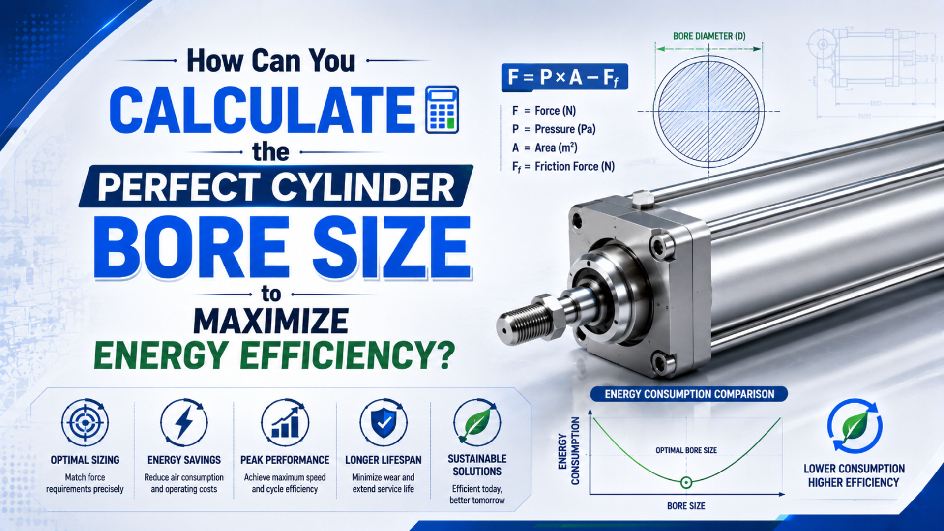
Calculate pneumatic cylinder bore size from the required load, motion direction, and lowest differential pressure expected at the cylinder during motion. Apply one documented allowance, move to the next available catalog bore, and then verify pull force, stroke time, cushioning, mounting, rod stability, and air demand before releasing the selection.
The energy-efficient choice is therefore not the smallest bore that works in a static equation. It is the smallest standard bore that still passes every force, motion, and safety requirement at the worst credible operating condition. A larger bore buys force reserve, but its area and charged volume rise with the square of diameter.
Key Takeaways
- A 50-to-63 mm bore step raises full piston area by 58.8% (AutomationDirect).
- Use dynamic differential pressure at the cylinder, not only the regulator setting.
- Calculate extension and retraction separately because the rod reduces pull-side area.
- Treat a calculated diameter as the minimum; select an available catalog bore and recheck it.
The Engineering Meaning of a “Perfect” Bore
ISO 15552 covers detachable-mounting pneumatic cylinders from 32 mm through 320 mm at a maximum rated pressure of 1,000 kPa, or 10 bar. Its purpose is dimensional interchangeability, not application sizing, so an ISO bore remains only a candidate until load, pressure, speed, mounting, and safety checks pass (ISO 15552, confirmed 2025).
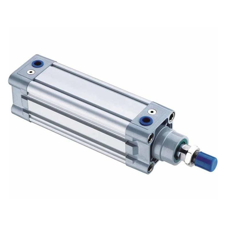
Cylinder bore is the internal barrel diameter that establishes the full piston area. It is not the outside width of the profile or end cap. For extension, pressure normally acts on the full piston area. For retraction on a single-rod cylinder, the rod removes part of that area.
The phrase “perfect bore” should mean three things at once:
- It produces the required net force at the lowest credible dynamic pressure.
- It completes the stroke within the allowed time without unacceptable impact or instability.
- It does not charge more cylinder volume than the application needs.
A force-only answer is incomplete. A 50 mm cylinder that passes a static push calculation can still stall on retraction, miss cycle time because of a restricted valve path, buckle its rod in compression, or hit the end cap with too much kinetic energy. Energy efficiency is one result of a sound selection, not a substitute for it.
Inputs to Freeze Before the Bore Calculation
SMC’s model-selection guide uses load ratios of 0.7 or less for static clamping and 0.5 or less for many vertical or horizontal dynamic loads, with lower ratios suggested for high speed. These are application-specific selection limits, not a universal safety-factor table (SMC Air Cylinder Model Selection, accessed 2026-07-18).
Freeze the following inputs before solving for diameter:
| Input | What to record | Why it changes bore |
|---|---|---|
| Required load force | Gravity, process force, friction, acceleration, and external resistance | Bore must overcome the total opposing force |
| Motion direction | Extension, retraction, or both | Retraction loses the rod area |
| Effective pressure | Lowest differential pressure across the two cylinder ports during the demanding part of motion | Force comes from differential pressure, not the compressor nameplate |
| Application allowance | One documented factor or manufacturer load ratio | Covers the selected operating risk without stacking arbitrary margins |
| Rod diameter | Actual catalog value for pull calculations | A larger rod reduces retract area |
| Stroke and cycle rate | Travel per movement and complete cycles per minute | These determine recurring charged volume |
| Stroke-time limit | Required extend and retract time | The valve, tubing, and exhaust path must fill and empty the chambers fast enough |
| Mounting and load path | Orientation, side load, pivot geometry, guides, and unsupported rod length | Bore alone does not correct bending moments or buckling |
Dynamic differential pressure is the pressure difference across the two working cylinder chambers while the actuator is moving under load. Application factor is the documented multiplier or load-ratio method used to convert the actual load into a theoretical force requirement for preliminary selection.
Measure pressure at the cylinder ports during motion when reviewing an installed machine. A regulator set to 6 bar does not prove that 6 bar remains available after filter, valve, fitting, tube, flow-control, and exhaust losses. If measurements are not yet available, use a defensible minimum design pressure and state that assumption on the sizing worksheet.
Do not stack a 25% force allowance, 20% friction deduction, 50% load ratio, and another “just in case” bore step without explaining how they interact. That method can hide duplicated conservatism and make the energy penalty impossible to audit. Use one coherent selection basis, then verify the real forces separately.
The force-factor selection guide explains the distinction between piston area, theoretical output, and manufacturer load ratio. This article carries the selected force basis forward into standard-bore choice, complete-cycle air demand, and energy cost.
Calculating Minimum Bore From Load and Pressure
AutomationDirect recommends calculated cylinder force at least 25% above the actual requirement as a practical starting allowance for friction, pressure drop, and related effects. It also solves bore from force, pressure, and piston area before selecting the next larger available diameter (AutomationDirect Cylinder Sizing, accessed 2026-07-18).
Let be bore diameter, rod diameter, full piston area, and rod area:
With effective differential pressure , theoretical extension and retraction forces are:
For metric calculations, pressure in MPa multiplied by area in mm² produces force in newtons. If pressure is entered in bar, convert it first:
If is the actual opposing load and is the selected application factor, calculate the required theoretical force as:
For extension, the minimum bore is:
For retraction with a known rod diameter, the minimum bore becomes:
These equations give a theoretical minimum. They do not select the mounting style, verify rod buckling, predict stroke time, or prove that the valve path can maintain the assumed pressure.
Selection rule: Start with the real opposing load and the lowest credible pressure difference at the cylinder. Calculate the required area for the working direction, move to the next available catalog bore, and then recalculate with that model’s actual rod diameter. A push-only calculation cannot approve a powered return stroke, and a regulator setpoint cannot prove the pressure available during motion. Keep the chosen application factor visible instead of stacking several hidden deductions. Finally, treat the result as a preliminary component candidate until valve flow, tubing, exhaust back pressure, mounting reactions, rod stability, cushioning, lost-air behavior, and machine acceptance testing have all passed. This sequence prevents the energy comparison from eliminating a larger bore that is genuinely required for reliable work.
The pneumatic cylinder formula guide provides the broader unit, area, speed, and air-use relationships. Keep this worksheet focused on the bore decision.
Worked Example: An 800 N Load at 5.5 bar
Using AutomationDirect’s 25% starting allowance, an 800 N load becomes a 1,000 N required theoretical force. At a measured minimum differential pressure of 5.5 bar, or 0.55 N/mm², the extension calculation returns 48.1 mm, which moves the first-pass selection to the next common bore: 50 mm (AutomationDirect, accessed 2026-07-18).
Assumptions for the example:
- Actual opposing load: 800 N
- Application factor: 1.25
- Required theoretical force: 1,000 N
- Minimum effective differential pressure: 5.5 bar
- Candidate rod diameter: 20 mm
- Required motion: powered extension and powered retraction
The required extension area is:
The corresponding bore is:
A 50 mm bore has 1,963 mm² of full piston area and produces about 1,080 N theoretical extension force at 5.5 bar. That clears the 1,000 N design requirement, but the pull-side result is different.
With a 20 mm rod, the 50 mm cylinder has about 1,649 mm² retract area and only 907 N theoretical pull force at the same differential pressure. It fails the 1,000 N requirement. Solving the retraction equation gives a minimum bore of about 52.1 mm, so the powered pull requirement moves the selection to 63 mm.
| Candidate | Full piston area | Retract area with 20 mm rod | Push force at 5.5 bar | Pull force at 5.5 bar | Result for 1,000 N requirement |
|---|---|---|---|---|---|
| 50 mm | 1,963 mm² | 1,649 mm² | 1,080 N | 907 N | Push passes; pull fails |
| 63 mm | 3,117 mm² | 2,803 mm² | 1,714 N | 1,542 N | Push and pull pass |
This is why direction belongs in the first line of the worksheet. If the 800 N process load exists only during extension and retraction carries a much lighter return load, 50 mm may remain valid. If 800 N must be pulled, 63 mm is the first common candidate under these assumptions.
In our experience, calculating the same stated load in both directions is the quickest way to expose a bore selection that looked acceptable only because rod area was omitted.
Choosing Between 50 mm and 63 mm
The step from 50 mm to 63 mm increases full piston area by 58.8%, because area follows diameter squared. AutomationDirect’s area-and-force relationship supports that calculation, but the larger area is justified only when the smaller bore cannot pass the documented load, pressure, direction, or motion checks (AutomationDirect, accessed 2026-07-18).
Use the following decision gates in order:
- Force gate: Calculate push and pull at the lowest dynamic differential pressure, including exhaust back pressure.
- Catalog gate: Select the next available bore and use its actual rod diameter, seals, and pressure rating.
- Load-path gate: Verify mounting reactions, side load, guide capacity, pivot geometry, and rod buckling in compression.
- Flow gate: Confirm that valves, fittings, tubing, silencers, and flow controls can meet the required stroke time.
- Energy gate: Compare complete-cycle air demand only between candidates that have passed the first four gates.
- Acceptance gate: Test the selected assembly under the worst credible load, supply pressure, cycle rate, and temperature.
A larger bore is not automatically slower. At fixed chamber flow, more area reduces theoretical piston speed, but a larger valve or shorter air path can change the result. The bore-size force and speed guide explains that interaction in detail.
Do not raise plant pressure simply to make an undersized candidate pass on paper. Higher pressure increases force, but it also changes air demand and can shift the restriction elsewhere. If pressure at the cylinder collapses during acceleration, use the pressure-drop troubleshooting guide before changing bore.
Air Demand After the Bore Decision
SMC’s 50 mm bore, 600 mm stroke, 0.5 MPa example uses about 13 L (ANR) per cylinder cycle, plus approximately 0.56 L for two meters of 6 mm-ID piping. SMC treats cylinder and switched-pipe volume as running-cost inputs and separates them from the flow required to achieve speed (SMC, accessed 2026-07-18).
For a single-rod, double-acting cylinder, calculate both swept volumes:
where is stroke. Convert the charged chamber volume to free-air equivalent with a clearly stated absolute-pressure and reference-temperature basis. NIST lists one standard atmosphere as 101,325 Pa and warns that standard gas-flow units can use different reference temperatures (NIST Pressure and Gas Flow Conversions, updated 2025-07-28).
The following screening comparison uses the worked example’s 5.5 bar gauge pressure, a 400 mm stroke, a 20 mm rod, and an approximate absolute-pressure ratio of 6.5. It excludes valve cavities, switched tubing, leakage, pilot air, and incomplete filling.
| Bore / rod | Approx. cylinder air per complete cycle | At 12 cycles/min | Difference from 50 mm |
|---|---|---|---|
| 50 / 20 mm | 9.39 L | 113 L/min | Baseline |
| 63 / 20 mm | 15.39 L | 185 L/min | +72 L/min |
The 63 mm candidate uses about 64% more cylinder air per complete cycle in this particular comparison. That does not make it wrong: it is the justified candidate when the pull requirement truly needs it. For a complete treatment of chamber volume, piping, and operating cost, use the bore-size air-consumption guide and the Air Consumption Calculator.
Converting Added Air Demand Into Energy Cost
CAGI’s verification program covers participating rotary compressors from 5 HP through 200 HP and defines specific power as input power per delivered flow at a stated discharge pressure. Cost calculations should therefore use measured or verified package performance, operating hours, and local electricity price (CAGI Performance Verification, accessed 2026-07-18).
For a screening estimate:
where is liters of free air per cycle and is complete cycles per minute. Then:
Here, is compressor package specific power in kW per m³/min, is active annual hours, and is electricity price per kWh.
Using the 72 L/min difference above, 7 kW per m³/min specific power, 3,000 active hours, and an electricity price of USD 0.12/kWh gives an illustrative difference of about 1,512 kWh and USD 181 per active year. This is not a savings promise. Compressor controls, unloaded power, storage, leaks, simultaneous demand, and production uptime can change the measured result.
Energy-cost boundary: A cylinder calculation estimates one end-use demand; it does not allocate the entire compressor room’s electrical bill with laboratory accuracy. Use complete-cycle air at a declared reference condition, measured cycles per minute, active production hours, and verified package specific power at the relevant discharge pressure. Include switched tube volume when it is material, and separate productive running from idle pressurization and leakage. Compare candidates that satisfy the same load, stroke-time, quality, and safety requirements. After installation, verify air per accepted production cycle under comparable conditions. This boundary keeps a geometric volume comparison useful without turning it into an unsupported plant-wide savings claim.
The U.S. Department of Energy’s MEASUR suite includes a Pneumatic Air Requirement calculator for single- and double-acting piston cylinders. Use it or the Compressed Air Energy Cost Calculator to cross-check a project with site-specific inputs (DOE MEASUR Calculator List, accessed 2026-07-18).
The Final Downsizing Verification
ISO 4414 addresses significant hazards in pneumatic systems and requires designers to consider reliable operation, adjustment, maintenance, energy efficiency, and intended use. Its scope is broader than a force equation, which is why a smaller calculated bore still needs a machine-level risk and performance review (ISO 4414, confirmed 2021).
Before approving a smaller bore, document:
- Push and pull force at minimum measured dynamic differential pressure
- Maximum load, acceleration, gravity, friction, process force, and load variation
- Rod buckling, side load, guide moments, mounting reactions, and alignment
- Extend and retract time at the actual valve, tube, fitting, and exhaust configuration
- Cushion capacity, moving mass, end-of-stroke speed, and external stopping method
- Lost-air behavior, stored energy, guarding, restart behavior, and required risk controls
- Complete-cycle air use, idle leakage, and air per accepted production cycle
- Acceptance results under low supply pressure and the worst credible production condition
The decision record should state why the selected bore passes, not merely that it is smaller. If the smaller candidate increases cycle time, stalls during a pressure sag, creates hard impacts, or requires higher plant pressure, the apparent air saving can disappear. Energy efficiency is achieved when the actuator completes useful work reliably with the lowest justified air demand.
Author and publisher information is available on the Jack Chen author page and About Us page. Use the contact page to submit load, pressure, direction, stroke, cycle-time, mounting, and environmental requirements for an application review.
FAQs About Pneumatic Cylinder Bore Size
AutomationDirect uses a 25% force allowance as a practical starting point, while SMC publishes load-ratio guidance that changes with static, dynamic, vertical, and high-speed operation. Those two first-party approaches show why bore selection needs an application basis rather than one universal margin (AutomationDirect; SMC, accessed 2026-07-18).
Is a 25% force allowance always enough?
No. It is a useful starting allowance from one supplier, not a universal safety rule. High speed, vertical load, changing friction, pressure loss, exhaust back pressure, human risk, or uncertain process force can require another documented selection basis. Use the applicable manufacturer data and machine risk assessment.
Should bore size use regulator pressure or cylinder-port pressure?
Use the lowest effective differential pressure expected across the cylinder during the demanding part of motion. Regulator pressure can be an early estimate, but valve, fitting, tube, flow-control, and exhaust losses can reduce actual force. Measure both cylinder ports under load when validating an installed machine.
Should I select the exact calculated bore diameter?
Usually no. Treat it as the minimum mathematical diameter, move to the next available catalog bore, and recalculate with that model’s actual rod diameter and pressure limits. Then verify mounting, speed, cushioning, buckling, air demand, and safety before approving the part number.
Why can retraction require a larger bore than extension?
The piston rod occupies part of the pressure-acting area during retraction. At the same differential pressure, the annular pull-side area produces less force than the full push-side piston area. Calculate both directions whenever the cylinder must do meaningful work while extending and retracting.
Does the smallest acceptable bore always use the least energy?
It normally charges less cylinder volume at the same stroke and pressure, but machine energy depends on the whole operating result. A smaller bore that needs higher pressure, longer stroke time, repeated retries, or poor process yield may not reduce energy per accepted cycle. Validate the complete machine under production conditions.
Sources and technical references
- AutomationDirect. Cylinder Sizing and Force. Retrieved July 18, 2026.
- Compressed Air & Gas Institute. Performance Verification. Retrieved July 18, 2026.
- International Organization for Standardization. ISO 15552:2018. Confirmed 2025. Retrieved July 18, 2026.
- International Organization for Standardization. ISO 4414:2010. Confirmed 2021. Retrieved July 18, 2026.
- National Institute of Standards and Technology. Pressure and Gas Flow Unit Conversions. Updated July 28, 2025. Retrieved July 18, 2026.
- SMC Corporation. Air Cylinders Model Selection. Retrieved July 18, 2026.
- U.S. Department of Energy. MEASUR Calculator List and Descriptions. Retrieved July 18, 2026.