

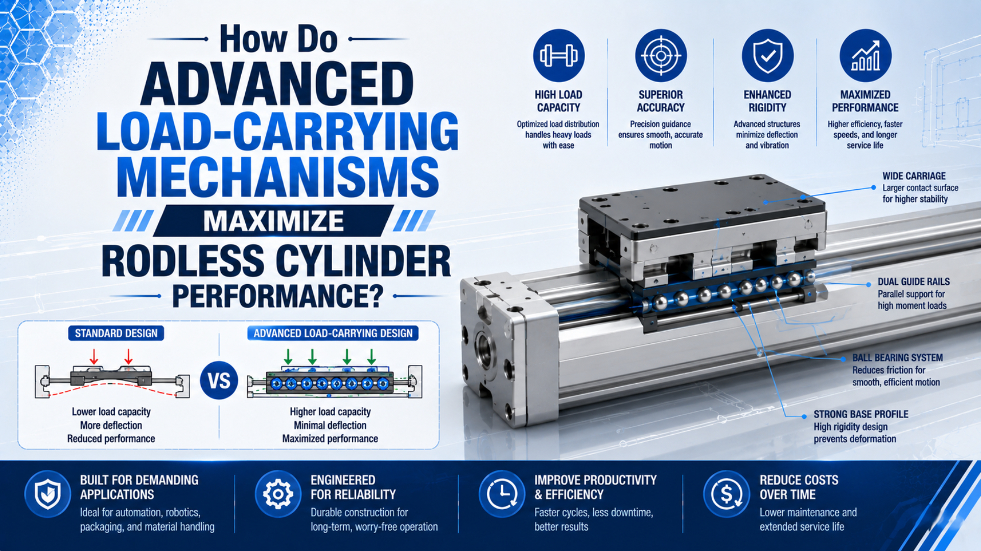
A rodless cylinder performs best when its drive mechanism transmits axial force and a correctly selected guide mechanism carries side loads and overturning moments. That separation is the basis of rodless cylinder load-carrying mechanisms. Treating the two jobs as one function is a common sizing error: bore size determines available thrust, but it does not prove that the carriage can safely support an offset payload.
Key takeaways: Separate thrust from guidance, calculate all applicable forces and moments, and check their combined utilization against the manufacturer’s model-specific limits. Parker’s OSP-P HD guide, for example, uses a five-term combined-load equation and requires the total utilization to remain at or below 1.0.
This guide explains how to map each load to the component that carries it, compare basic and guided architectures, calculate offset moments, and account for speed, cushioning, magnetic holding force, and external guidance before you specify a cylinder.
Which Parts Carry Which Loads in a Rodless Cylinder?
Source benchmark: Parker’s OSP-P HD guide evaluates five normalized load components—three moments and two forces—in one interaction equation. The current OSP-P catalog therefore treats carriage guidance as a separate selection problem from the piston force that drives the axis.
The phrase “load-carrying mechanism” can describe several different parts. Start by separating their jobs:
| Component or mechanism | Primary job | What it does not prove |
|---|---|---|
| Piston and effective area | Convert air pressure into axial thrust | Carriage moment capacity |
| Mechanical slot, magnetic coupling, or cable | Transfer piston motion to the external carriage | Adequate guidance for an offset payload |
| Carriage bearings or integrated guide | Resist supported forces and moments within published limits | Sufficient axial thrust or cushioning |
| Cylinder tube and mounting structure | Maintain alignment and support the actuator span | Machine-frame rigidity |
| End cushion or shock absorber | Dissipate moving energy near end of stroke | Static load capacity |
| Machine frame and mounting brackets | Carry reaction forces into the machine | Compensation for a misaligned payload rail |
A mechanically jointed rodless cylinder transfers piston force through a slot to the external carriage. A sealing-band system closes that slot; the band is not the payload guide. A magnetically coupled cylinder transfers force through the tube wall, while a cable cylinder transfers motion through a cable-and-pulley arrangement. These are drive-coupling choices, not automatic statements about load guidance.
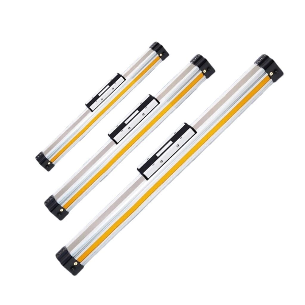
This distinction also explains why two cylinders with the same bore and stroke can have very different permitted loads. Their theoretical thrust may be similar, but bearing spacing, rail geometry, carriage length, mounting orientation, and guide construction can produce different force and moment ratings.
If you first need to compare drive principles, see the overview of rodless pneumatic cylinder types. For mechanically coupled designs, the separate discussion of rodless-cylinder sealing-band technology explains sealing rather than guidance.
How Do Basic, Slide-Bearing, Cam-Follower, and Linear Guides Differ?
Source benchmark: SMC currently divides its MY1 mechanically jointed family into five guide architectures: basic, slide bearing, cam follower, linear guide, and high-rigidity linear guide. The MY1 catalog index shows why “rodless cylinder” alone is not a complete guide-capacity specification.
Guide names are not interchangeable load classes. They describe different bearing arrangements, and the permitted forces and moments must still come from the exact manufacturer’s datasheet. SMC’s MY1 platform illustrates the range clearly: the current catalog lists basic, slide-bearing, cam-follower, linear-guide, and high-rigidity linear-guide versions. That is a useful architecture map, not a universal ranking for every brand.
| Guide architecture | Typical design intent | Selection questions |
|---|---|---|
| Basic, non-integrated guide | Drive an externally guided load or carry a small, well-centered payload | Where will side force and moment be reacted? |
| Slide bearing | Compact integrated support with sliding contact | What friction, contamination, and wear behavior does the application permit? |
| Cam follower | Rolling contact on prepared guide surfaces | What adjustment, preload, and service access are required? |
| Linear guide | Recirculating rolling elements for higher stiffness and repeatable guidance | Are moment, cleanliness, lubrication, and alignment requirements compatible? |
| High-rigidity linear guide | Larger bearing separation or stronger rail/carriage arrangement | Do the published combined-load and dynamic limits cover the actual duty? |
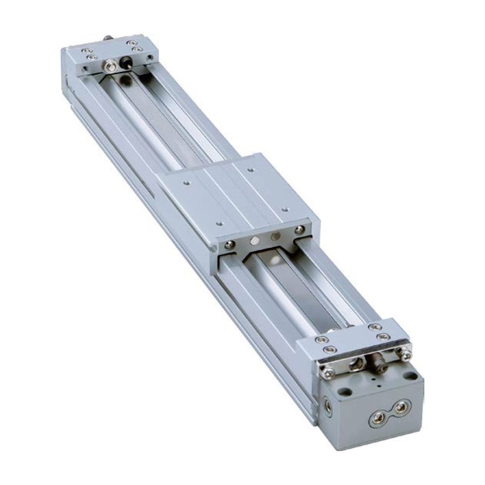
A basic cylinder can be the correct choice when a machine already has a well-aligned linear rail. Adding a second rigid guide without a suitable floating connection may overconstrain the system. Conversely, mounting a tall fixture directly on a basic carriage can create an overturning moment that the actuator was never intended to carry.
The practical question is therefore not “Which guide is strongest?” but “Where does each load close its force loop?” If a payload moment passes through the actuator bearings, include it in actuator selection. If a separate machine rail carries it, verify rail capacity, parallelism, and the connection that transfers axial drive without forcing the cylinder to absorb rail misalignment.
How Should You Calculate Static and Dynamic Moment Loads?
Source benchmark: Tolomatic’s motion-design guidance calls for checking moments about all three axes from the payload and center-of-mass offsets. That three-axis check matters because a load that looks acceptable by mass alone can exceed a carriage moment rating when its fixture is tall or cantilevered.
Draw the payload, carriage, center of mass, acceleration direction, gravity direction, and every offset before opening a catalog. Manufacturers may label the three moment axes differently, so match your sketch to the coordinate diagram for the exact series rather than relying on memory.
For a payload mass , the gravitational force is:
where is approximately 9.81 m/s². A force acting at a perpendicular offset creates a moment:
Acceleration adds an inertial force:
Suppose a 20 kg payload has its center of mass 0.15 m from the relevant bearing axis. Its gravitational force and static moment are:
If that same mass accelerates at 2 m/s² and the inertial force acts with a 0.15 m perpendicular offset, then:
Do not add 29.43 N·m and 6 N·m automatically. First determine whether they act about the same axis and in the same direction at the same operating instant. Also include the mass of tooling, adapter plates, cable carriers, workpieces, and any part of the carriage assembly that the actuator must accelerate.
Tolomatic’s motion-design guidance similarly recommends calculating moments about all three axes from the load and center-of-mass offsets. Its warning is important: a published maximum may represent one moment acting alone, while a real machine applies several loads at once. That is why the next step is a combined-load check rather than a collection of separate pass/fail comparisons.
For a broader explanation of the failure mechanism, review how side loading damages linear actuators.
How Do You Check Combined Loads?
Source benchmark: For its OSP-P HD heavy-duty guide, Parker requires the sum of five normalized force and moment terms to be no greater than 1.0. The catalog also says its published maximums apply to light, shock-free operation and must not be exceeded dynamically.
Use the load-combination method specified for the exact guide. Parker publishes the following utilization equation for the OSP-P HD heavy-duty guide:
Here, , , and are the applied moments; and are the applied forces; and each “max” term is the corresponding permitted value for the selected model and size. A result of 0.72 means the listed loads consume 72% of the permitted combined-load envelope under the catalog’s stated conditions—it does not mean the complete machine has a universal 28% safety margin.
This equation is manufacturer- and guide-specific. Do not transfer Parker ratings or its interaction rule to an SMC, Tolomatic, Festo, or other actuator unless that manufacturer explicitly uses the same method. Some catalogs provide selection graphs, orientation factors, allowable kinetic energy, or software instead.
The Parker catalog also states that its published maxima are for light, shock-free operation and must not be exceeded dynamically. Check these conditions before accepting a result:
- Does the table apply to the selected bore, carriage, stroke, and guide option?
- Is the quoted limit static, dynamic, or valid only below a stated speed?
- Are multiple forces and moments simultaneous?
- Does orientation change bearing loading or cushion behavior?
- Is the actuator supported over a long span, or will tube deflection affect alignment?
- Are stops, shocks, vibration, or emergency deceleration present?
- Does the required service factor come from the manufacturer or your company’s design standard?
In our experience reviewing sizing calculations, a one-page load sketch often exposes more errors than starting with a bore table. It makes missing offsets, forgotten tooling mass, and unsupported side loads visible before a model number creates false confidence.
What Changes with Magnetic Coupling?
Source benchmark: SMC lists magnet holding forces from 19.6 N to 2256 N across the bore range in its CY3R series catalog. Those figures define model-specific axial coupling limits; they are not side-load or overturning-moment ratings for the external carriage.
For a magnetically coupled rodless cylinder, compare magnetic holding force with required axial drive force, then evaluate guidance separately. The magnets transmit piston motion through a nonmagnetic tube wall. If the demanded axial force exceeds the coupling’s holding capability, the internal and external magnetic assemblies can decouple even when the pneumatic bore could theoretically generate more thrust.
SMC’s CY3R catalog, for example, lists model-specific magnet holding forces from 19.6 N to 2256 N across its bore range. Those values are not generic ratings for all magnetic cylinders, and they are not permitted side-load or moment values. The same catalog specifies a 0.7 MPa maximum operating pressure and a 50–500 mm/s piston-speed range for that series.
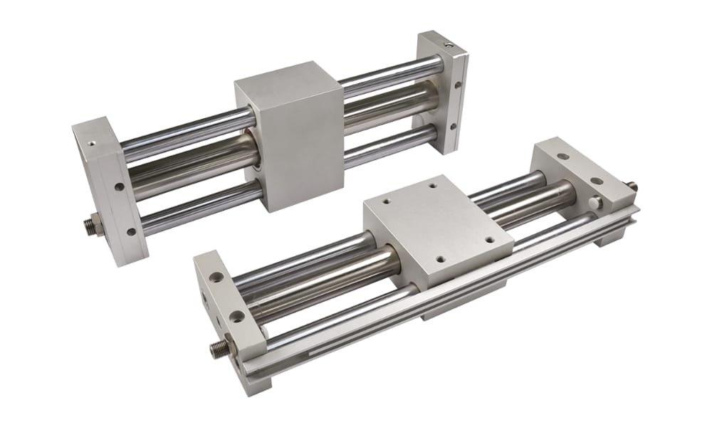
SMC’s magnetic rodless-cylinder selection guidance separates non-integrated types for light loads or externally guided mechanisms from guide-integrated types that directly carry the load. This distinction is the safest way to read any magnetic-cylinder proposal: ask for the allowable coupling force and the allowable guide loads as separate data.
If contamination isolation or a sealed tube is the reason for considering this architecture, the magnetic rodless cylinder operating guide covers the drive principle in more detail.
How Do Speed and Cushioning Reduce Usable Load?
Source benchmark: Parker’s OSP-P basic sizing information notes that cushion-entry velocity can be about 50% higher than average travel velocity, depending on the profile. Because kinetic energy varies with velocity squared, average cycle speed alone can materially understate the end-of-stroke energy the cushion must absorb.
Static capacity is only one boundary. A moving assembly also stores kinetic energy:
Because velocity is squared, doubling speed produces four times the kinetic energy at the same moving mass. The end cushion, shock absorber, or external stop must dissipate that energy without causing excessive impact, rebound, or structural load.
Use the cushion-entry velocity, not merely the average stroke speed. Parker notes in its OSP-P sizing information that entry speed into the cushion can be about 50% higher than average velocity, depending on the motion profile. Also include the moving carriage, mounting plate, tooling, workpiece, and cable-management mass—not only the nominal payload.
The selection sequence should therefore check at least three independent boundaries:
- Axial force: available cylinder force after accounting for operating pressure and system losses.
- Guide loading: individual and combined forces and moments at the worst operating instant.
- Deceleration energy: cushion or shock-absorber capacity at actual entry speed.
You can use the pneumatic cylinder force calculator for an initial thrust estimate and the cylinder cushion energy calculator for a first-pass energy check. Final selection must still follow the manufacturer’s data and application factors. The guide to pneumatic cylinder cushioning explains adjustment and end-of-stroke behavior.
When Should You Use an External Guide?
Source benchmark: SMC’s magnetic rodless-cylinder selection guide separates non-integrated models for light loads or external guidance from guide-integrated models that directly carry the load. That two-path architecture makes the support decision explicit instead of asking the drive coupling to serve as a payload bearing.
An external linear rail is often appropriate when the machine—not the cylinder—should control payload alignment. Consider it when one or more of the following apply:
- The center of mass is far from the actuator carriage.
- Tooling creates high pitch, yaw, or roll moments.
- The payload requires tighter straightness, flatness, or stiffness than the actuator guide provides.
- The cylinder must drive a wide gantry or a load supported at multiple points.
- Process forces act perpendicular to travel.
- Long stroke, heavy cable carriers, or unsupported span makes deflection important.
- The environment requires a specialized rail, scraper, lubricant, or protective cover.
- The application needs a replaceable precision guide independent of the pneumatic drive.
Do not rigidly bolt two imperfectly parallel guide systems together and assume more bearings always improve capacity. Parallelism errors can create internal binding loads that do not appear in the payload calculation. Depending on the manufacturer and layout, a floating joint or compliant drive connection can let the external rail control alignment while the cylinder supplies axial force.
Specify installation tolerances, mounting reference surfaces, rail alignment procedure, and allowable compliance. Then verify that the connection cannot introduce a new moment into the cylinder carriage. A larger bore can increase thrust, but it cannot correct an overconstrained structure.
What Data Belong in a Rodless Cylinder RFQ?
Source benchmark: Tolomatic’s 10 pneumatic rodless actuator sizing tips organize selection around more than one nominal load value. Stroke, orientation, velocity, acceleration, load position, and cushioning all affect the result, so an RFQ needs a load case that a supplier can reproduce.
A useful request for quotation contains the load case, not just bore and stroke. Send the supplier enough information to reproduce your selection:
| RFQ data | What to provide |
|---|---|
| Motion | Stroke, orientation, target cycle time, velocity profile, acceleration, deceleration, and dwell |
| Pneumatics | Minimum pressure at the actuator during motion, available flow, valve and tube sizes |
| Moving mass | Payload, fixture, plate, carriage accessories, workpiece range, and cable carrier |
| Load geometry | Center-of-mass offsets in three axes and locations of external process forces |
| Guidance | Basic, integrated guide, or external rail; connection and alignment concept |
| End-of-stroke control | Cushion type, shock absorber, external stop, and emergency-stop condition |
| Duty and environment | Cycles, shift pattern, temperature, contamination, washdown, corrosion, and lubrication limits |
| Acceptance criteria | Position repeatability, deflection, settling time, impact, leakage, and service-life target |
Attach a dimensioned sketch showing the coordinate system. Ask the supplier to return the selected model, allowable forces and moments, combined-load result, cushioning check, mounting assumptions, and any required derating. This makes competing proposals comparable and prevents a thrust-only selection from being mistaken for a complete design review.
How Should You Validate the Selected Mechanism?
Source benchmark: Parker publishes OSP-P load and moment data with stated operating conditions, including a load-data velocity limit of 0.5 m/s in its basic cylinder catalog. A machine test must therefore verify the selected cylinder under the real speed, mass, pressure, and deceleration profile rather than assuming one table covers every condition.
Catalog sizing should be followed by machine-level validation. Run the actuator at minimum expected supply pressure and maximum production mass, because pressure at the actuator can fall below the compressor or regulator setpoint during high flow.
A practical acceptance test should cover:
- Low-speed breakaway and high-speed operation over the full stroke.
- Maximum payload and the worst center-of-mass offset.
- Normal and emergency deceleration conditions.
- Cushion adjustment, impact noise, rebound, and stop repeatability.
- Carriage deflection and guide temperature after thermal stabilization.
- Binding or force spikes at several stroke positions.
- Magnetic-coupling stability, where applicable, under peak acceleration.
- Fastener retention, bearing play, sealing-band tracking, and leakage after the planned endurance sample.
Record pressure at both cylinder ports, cycle time, carriage position, and any abnormal sound or temperature trend. Do not infer a universal service-life number from a short acceptance test; define the endurance duration and pass criteria from the application risk and the supplier’s documented life method.
Conclusion
Source benchmark: The Parker OSP-P HD selection method reduces three moments and two transverse forces to one utilization value that must remain at or below 1.0. It captures the central lesson: safe rodless-cylinder selection depends on the load path and load combination, not payload mass alone.
Advanced load-carrying mechanisms maximize rodless cylinder performance by putting each force in the correct path. The piston and coupling provide axial motion; the carriage, integrated guide, or external rail supports payload forces and moments; and the cushion manages end-of-stroke energy.
The reliable workflow is simple: draw the load geometry, calculate static and inertial forces, convert offsets into moments, apply the exact manufacturer’s combined-load method, and check force and cushioning separately. Then validate the selected architecture on the machine. This process is more defensible than choosing by bore, guide label, or payload mass alone.
Rodless Cylinder Load-Carrying Mechanism FAQs
Source benchmark: The Parker OSP-P HD guide catalog combines five normalized load terms and requires their sum to stay at or below 1.0. These FAQs apply that model-specific example to the broader selection errors that most often blur axial drive force, guidance, moments, and cushioning.
Does the magnetic coupling carry the payload?
The magnetic coupling transmits axial motion between the internal piston and external carriage. It does not automatically establish side-load or moment capacity. Compare required axial force with the model’s holding force, then use the guide ratings—integrated or external—to determine whether the payload forces and offsets are acceptable.
Is a larger bore enough for a heavier rodless-cylinder load?
No. A larger bore generally increases available axial thrust at the same pressure, but a heavier or more offset payload also increases guide force, overturning moment, and cushion energy. Check bore force, combined guide loading, tube support, and deceleration capacity as separate limits using data for the exact actuator configuration.
Which guide type handles the highest moments?
There is no universal winner based only on a guide label. High-rigidity linear guides are designed for demanding loads, but permitted moments depend on model size, bearing spacing, carriage option, speed, and load combination. Compare the exact catalog ratings and interaction method instead of transferring a ranking between manufacturers.
How do I calculate an offset load moment?
Multiply the applied force by its perpendicular distance from the relevant bearing axis: . For a mass under gravity, first calculate . Repeat for inertial and process forces, map each result to the manufacturer’s coordinate system, and evaluate simultaneous loads together.
When does a rodless cylinder need an external guide?
Use an external guide when payload moments, process side forces, stiffness, accuracy, or span requirements exceed what the cylinder carriage should carry. The rail must be sized for those loads and aligned correctly. A floating or compliant drive connection may be needed to prevent parallel guide systems from binding each other.
Sources and technical references
-
Parker OSP-P rodless cylinder catalog — OSP-P HD guide construction, permitted forces and moments, combined-load equation, and dynamic-use cautions.
-
Parker OSP-P basic cylinder sizing information — load and moment selection, cushion performance, velocity conditions, and force-times-distance moment calculation.
-
SMC MY1 mechanically jointed rodless cylinder catalog — basic, slide-bearing, cam-follower, linear-guide, and high-rigidity guide variants.
-
SMC MY1M slide-bearing model page — current integrated slide-bearing series reference.
-
SMC CY3R magnetic rodless cylinder catalog — model-specific holding forces, pressure limit, and piston-speed range.
-
SMC magnetic rodless cylinder model-selection guide — non-integrated and guide-integrated magnetic cylinder selection.
-
Tolomatic motion-design guidance — moment calculations about three axes and caution about simultaneous loads.
-
Tolomatic pneumatic rodless actuator sizing tips — application inputs for rodless pneumatic actuator selection.