

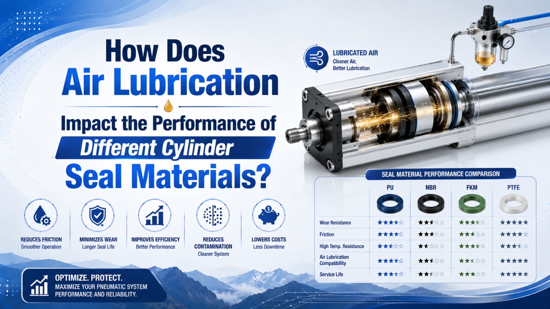
Air lubrication can lower friction in an approved pneumatic cylinder, but it can also wash out factory grease, carry oil into a clean process, or expose a seal to an incompatible additive package. NBR, polyurethane, FKM, and PTFE are material families, not fixed lubrication instructions. The cylinder manual and exact compound must control the decision.
Air lubrication is the controlled introduction of oil into a compressed-air stream for downstream components that are specifically approved for that oil feed. It is different from the grease applied inside a cylinder during assembly and from unintended compressor-oil carryover.
That distinction matters most when a maintenance team wants to add a lubricator, change the oil grade, or stop an existing oil feed. The safe question isn’t “Which polymer likes oil?” It is “Was this complete sealing system qualified for this lubrication regime, oil chemistry, temperature, motion, and process?”
Key Takeaways
- SMC specifies ISO VG32 turbine oil for applicable lubricated products and warns that added oil can displace factory lubricant.
- A family name such as NBR or PTFE cannot approve an oil change.
- Use a 5-step review: identify, screen, test, commission, and monitor.
- Don’t stop an established oil feed until the cylinder manufacturer approves the change.
Which Lubrication Regime Is the Cylinder Actually Running?
Start by classifying the operating regime, because “dry” and “lubricated” are not precise enough. SMC specifies ISO VG32 turbine oil for applicable products and says that once added oil has displaced the original lubricant, the oil supply must continue (SMC Lubricants Used to Supply Lubrication, accessed 2026).
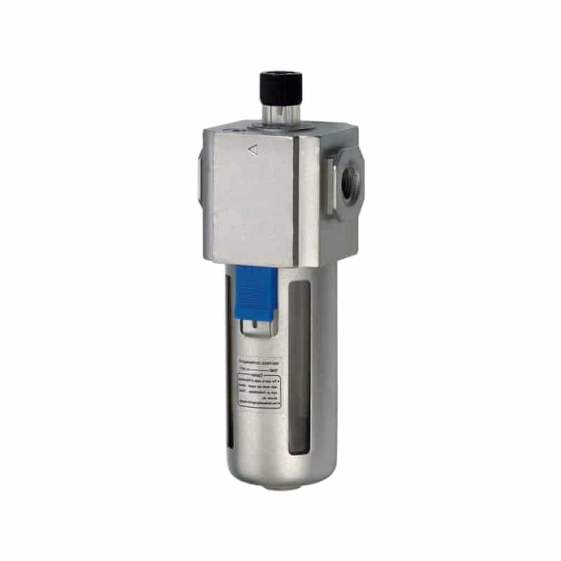
An air-line lubricator changes the oil exposure of every compatible downstream cylinder, valve, and accessory on its branch.
Four regimes cover most maintenance decisions:
| Lubrication regime | What it means | First document to check |
|---|---|---|
| Factory-lubricated, no airline oil | Grease was applied during assembly; no routine oil mist is supplied | Cylinder datasheet and service manual |
| Continuous airline oil | A lubricator intentionally meters oil into the downstream air | Approved oil grade, feed rule, and branch layout |
| Incidental oil carryover | Compressor oil, upstream residue, or cross-connected air reaches the cylinder unintentionally | Air-quality record and contamination investigation |
| Lubricant-film disturbance | Cleaning, solvent, washdown, very dry air, heat, or maintenance changes the original film | Cleaning instruction, grease specification, and seal-kit procedure |
A non-lube cylinder isn’t necessarily free of lubricant. Many designs depend on grease applied at assembly, then retain enough film to run without routine oil mist under specified conditions. The self-lubricating seal guide explains that mechanism in detail.
Lubrication regime is the documented combination of factory grease, deliberate airline oil, incidental oil carryover, cleaning exposure, and operating conditions that determines what reaches a cylinder’s sliding interfaces.
What if the rod looks dry? Appearance alone can’t distinguish correct non-lube operation from grease removal, oil starvation, or an incompatible cleaner. Record the cylinder code, seal-kit code, factory lubricant, current oil, lubricator setting, last cleaning action, and the date the regime changed.
Treat lubrication as a controlled system state, not a maintenance preference. Once the state changes, every downstream seal, valve, exhaust path, product-contact risk, and service instruction may change with it.
Why Can’t NBR, Polyurethane, FKM, and PTFE Be Ranked by Oil Tolerance?
Material-family rankings fail because compounds within one family behave differently. Parker identifies N0674-70 as a standard NBR compound resistant to mineral oil and commonly suited to hydraulic and pneumatic systems, directly contradicting the blanket claim that NBR must use oil-free air (Parker O-Ring Handbook, accessed 2026).
The material name is only the first screening field. A finished seal also has a profile, hardness, energizer, fillers, cure system, lip loading, groove, counterface, and assembly lubricant. Change any of those and the friction, swelling, wear, leakage, or installation risk can change too.
| Material family | Useful screening clue | What the family name cannot prove |
|---|---|---|
| NBR | Many compounds resist mineral oils and work in general pneumatic service | Compatibility with every synthetic oil, additive, temperature, ozone level, or dynamic profile |
| Polyurethane | Pneumatic grades can offer strong wear and extrusion resistance | Whether the grade is polyester- or polyether-based, hydrolysis resistant, or compatible with the selected oil |
| FKM | Many grades offer useful heat and oil resistance | Low-temperature flexibility, dynamic friction, or compatibility with every chemical and additive package |
| PTFE-based | Filled compounds can provide low friction and broad chemical resistance | Whether the profile can run dry, needs an energizer, requires a transfer film, or matches the counterface |
Trelleborg lists pneumatic profiles in optimized polyurethane and PTFE-based materials, which shows why the seal geometry and compound are selected together rather than as interchangeable rings (Trelleborg Pneumatic Seals, accessed 2026). Parker also evaluates PTFE compounds under dry-running test conditions, so PTFE doesn’t universally require oil mist (Parker PTFE Material Data, accessed 2026).
Could a generic chart still help? Yes, but only to reject obvious mismatches or identify questions for the supplier. The broader seal compatibility guide explains why exact compound identity, seal position, hardware, exposure, and acceptance evidence must pass together.
What Changes When You Add, Remove, or Replace Airline Oil?
An oil change alters more than friction. SMC permits ISO VG32 turbine oil without additives for applicable products, warns that other oils can damage seals or cause malfunction, and requires continued lubrication after added oil washes away the original lubricant (SMC Lubricants Used to Supply Lubrication, accessed 2026).
Adding oil to a factory-lubricated cylinder
Added oil may reduce friction initially, yet that doesn’t prove compatibility or longer life. It can dilute or transport the assembly grease, change seal swell and hardness, collect particles, alter valve response, and create oil carryover at exhausts. The change may also turn an occasional adjustment into a permanent refill obligation.
Before installing a lubricator, confirm that every component downstream permits oil mist. A branch may contain a cylinder, directional valve, quick exhaust valve, flow control, silencer, sensor housing, and process nozzle. One incompatible or contamination-sensitive component is enough to reject the change. Use the FRL maintenance guide for the hardware checks after lubrication has been approved.
Stopping an existing oil feed
Stopping oil can be riskier than starting it. If continuous oil has replaced the original grease film, the seals and guides may lose lubrication before anyone notices a visible leak. Don’t bypass an empty lubricator as a quick experiment. Obtain the cylinder manufacturer’s written instruction, define the cleaning or rebuild method, and decide whether a seal-kit replacement is required.
Replacing one oil with another
Two oils with the same viscosity grade aren’t automatically interchangeable. Base oil, anti-wear additives, detergents, oxidation inhibitors, water content, and contamination can affect elastomers and greases differently. Ask for the oil’s technical data and safety data, then compare the exact old and new products. “ISO VG32” describes viscosity classification, not complete chemical equivalence.
Why not install a coalescing filter after the lubricator to remove excess oil? That arrangement defeats the intended oil feed and doesn’t establish a controlled dose at the cylinder. Correct the lubricator selection, location, feed setting, and branch design instead.
A Five-Step Lubricant or Oil-Grade Change Approval
Use a staged approval rather than a family-level compatibility claim. ISO 1817:2024 compares vulcanized or thermoplastic rubber properties before and after liquid immersion, making it suitable for material screening, but the standard does not by itself qualify a moving pneumatic seal or complete cylinder (ISO 1817:2024).
Follow these five steps:
-
Identify the installed system. Record the complete cylinder model, revision, seal-kit number, seal positions, compound codes, factory grease, valve and accessory models, pressure, temperature, speed, stroke, load, dwell, and air-quality history.
-
Screen the exact lubricant. Compare the oil and its additives with the seal supplier’s data. Include factory grease, cleaners, compressor carryover, water, and any process chemicals. Don’t approve from the words “NBR,” “PU,” or “PTFE” alone.
-
Test the material when evidence is incomplete. Agree on the actual oil, temperature, exposure time, properties, samples, and acceptance limits before an ISO 1817-type immersion comparison. Volume, mass, hardness, dimensions, tensile behavior, and appearance may all matter.
-
Test the assembled function. Inspect the groove, rod, bore, guides, lip direction, assembly method, leakage, breakaway, stroke time, temperature, cushioning, and sensor response. Coupon compatibility can’t reveal a damaged rod or incorrect seal profile.
-
Release and monitor. Establish a baseline and a follow-up trigger in cycles, accumulated travel, or operating hours. Record who approved the change and what evidence would require rollback.
In our experience, the missing field is often the original assembly grease. Teams compare the new oil with a seal family, yet nobody records what the oil will mix with inside the cylinder. That gap can explain why a chemically acceptable oil still changes friction or washes lubricant away from a guide surface.
The industrial cylinder seal-type guide helps identify whether the affected part is a rod seal, piston seal, wiper, static seal, cushion seal, or guide element. That position must be known before interpreting material data.
Failure Evidence That Points to a Lubrication Problem
Compare the changed cylinder with a documented baseline rather than a universal life claim. ISO 19973-3:2015 expresses pneumatic-cylinder reliability in two service measures, cycles or kilometres, and requires defined test conditions and failure thresholds (ISO 19973-3). A raw cycle count can’t identify the cause.
| Observation | Lubrication-related possibility | Other causes to exclude |
|---|---|---|
| Seal swelling or loss of groove fit | Fluid absorption or incompatible oil/additives | Wrong compound, heat, cleaner exposure, incorrect groove |
| Hardening, cracking, or permanent set | Chemical extraction, oxidation, heat, or lubricant interaction | Age, ozone, over-compression, excessive temperature |
| Higher breakaway force or stick-slip | Film loss, contamination, wrong grease, altered transfer film | Side load, poor alignment, rough surface, undersized valve or flow control |
| Oil at exhaust or product area | Excess feed, branch carryover, wrong lubricator location | Compressor carryover or another lubricated branch |
| Rapid lip wear or scoring | Inadequate film, abrasive paste, incompatible oil | Damaged rod or bore, debris, bad guide, sharp assembly path |
| Leakage after a lubricant change | Swell, shrinkage, friction change, damaged lip | Loose joint, reversed seal, pressure spike, valve leakage |
One symptom isn’t a diagnosis. A swollen seal suggests fluid interaction, but the fluid may be a washdown chemical or compressor oil rather than the lubricator oil. A glazed polyurethane lip may reflect heat and side load. A worn PTFE-based seal may point to the counterface, filler, installation, or transfer film.
What should be retained after a failure? Keep the seal in a labeled clean container, photograph its installed orientation, preserve a sample of the oil, and record temperature, pressure, stroke, speed, cycle history, cleaning events, and the failed direction. Don’t clean away the evidence before inspection.
The most useful comparison is often upstream versus downstream of the change. If identical cylinders on an unmodified branch remain stable while units after the lubricator change show the same new symptom, the branch history becomes evidence. It still doesn’t replace compound verification, but it gives the investigation a controlled starting point.
How Should You Commission the Changed Lubrication System?
Commission the complete cylinder, not just the oil. ISO 10099:2001 defines final functional examination and acceptance testing for double-acting, single-rod pneumatic cylinders, and ISO confirmed the standard in 2023 (ISO 10099). Use it with the model manual and machine-specific limits.
First isolate hazardous pneumatic and mechanical energy according to the machine’s approved procedure. OSHA 29 CFR 1910.147 treats pneumatic energy as an energy source that must be controlled during servicing (OSHA 1910.147). Restrain gravity loads, exhaust stored pressure, verify isolation, and keep hands clear of the actuator path.
Then build a reproducible acceptance record:
| Stage | Record | Reject or investigate when |
|---|---|---|
| Incoming check | Cylinder code, seal kit, oil, grease, lubricator, batch or lot | Identity or approval evidence is missing |
| Initial low-risk cycling | Pressure, speed, stroke time, sound, motion, external leakage | Motion is erratic, leakage appears, or temperature rises abnormally |
| Loaded function | Load, orientation, dynamic pressure, cushions, sensors, end positions | The cylinder stalls, impacts, drifts, or misses its required position |
| Stabilized inspection | Oil migration, exhaust contamination, rod film, temperature, leakage | Oil reaches a prohibited area or behavior departs from baseline |
| Follow-up | Cycles or travel, observations, maintenance action, release owner | Trend worsens or the same failure mode returns |
Don’t declare success after one smooth stroke. A changed film may affect breakaway after a long dwell, cold startup, short repetitive strokes, or temperature stabilization. Test the states that matter to the real machine, then retain the baseline for the next inspection.
When Should You Reject External Air Lubrication?
Reject external oil when the product manual prohibits it or the process can’t tolerate carryover. ISO 8573-1:2010 classifies three main compressed-air contaminant groups, particles, water, and oil, but those purity classes don’t approve a seal compound or permit oil in a clean process (ISO 8573-1).
External lubrication is usually the wrong corrective action when:
- The cylinder is specified for factory-lubricated, non-lube service and shows no lubrication-related fault.
- The manual prohibits added oil or requires a product-specific grease.
- Oil could contaminate food, pharmaceuticals, electronics, paint, optics, cleanroom work, or analytical instruments.
- Exhaust oil would create an environmental, housekeeping, or worker-exposure problem.
- The branch includes components that aren’t approved for oil mist.
- Friction is actually caused by side load, misalignment, a scored rod, damaged guides, poor flow control, or incorrect seal installation.
- Nobody can identify the oil, seal compound, factory grease, or acceptance limit.
For clean applications, “non-lube” is only one requirement. The cleanroom cylinder guide covers grease, particle generation, exhaust routing, cleaning, and validation as separate decisions.
Would oil mask a mechanical fault for a few shifts? It might. That is exactly why smoother motion after adding oil doesn’t prove the repair is safe. Correct the root cause, then approve any lubrication change through the same documented process.
Air Lubrication and Cylinder Seal FAQs
Parker’s compatibility tables use four numbered ratings plus X for insufficient data, a reminder that screening contains uncertainty even before motion, grooves, and surface finish are considered (Parker O-Ring Handbook, accessed 2026). These answers keep material screening separate from final cylinder approval.
Does NBR perform best with oil-free compressed air?
No. Parker identifies N0674-70 NBR as resistant to mineral oil and generally suited to pneumatic and hydraulic systems. That doesn’t approve every NBR compound or oil. Check the exact compound, oil additives, temperature, ozone, motion, groove, and factory grease before deciding whether oil-free or lubricated operation is appropriate.
Can I add oil to a non-lube pneumatic cylinder?
Only if the model-specific instructions permit it. SMC specifies ISO VG32 turbine oil for applicable products and warns that introduced oil can wash away the original lubricant. Once that happens, the supply must continue. Also verify every downstream component and confirm that oil carryover is acceptable to the process.
Does PTFE require oil mist to prevent wear?
Not universally. Parker tests PTFE material wear under dry-running conditions, while pneumatic suppliers use different filled PTFE compounds, energizers, profiles, and counterfaces. Some assemblies need initial grease or an approved film; others can operate without airline oil. The finished-seal datasheet and application test decide, not the PTFE label.
Can ISO 8573-1 select a cylinder seal material?
No. ISO 8573-1:2010 classifies compressed-air purity for particles, water, and oil. It doesn’t specify which NBR, polyurethane, FKM, or PTFE compound fits a cylinder. Use the air-quality class as one exposure input, then verify the exact seal, lubricant, temperature, motion, and hardware separately.
What evidence should approve a lubricant change?
Use five linked records: cylinder and seal identity, exact oil and factory grease, compound-level screening, relevant ISO 1817-type material testing where evidence is incomplete, and an assembled-cylinder acceptance test. Add a baseline plus a follow-up trigger in cycles, travel, or hours. Missing identity or limits means approval is premature.
Sources and technical references
-
SMC Lubricants Used to Supply Lubrication. Retrieved 2026-07-18.
-
Parker O-Ring Handbook. Retrieved 2026-07-18.
-
Parker PTFE Material Data and Dry-Running Wear Testing. Retrieved 2026-07-18.
-
Trelleborg Pneumatic Seals. Retrieved 2026-07-18.
-
ISO 1817:2024, Rubber resistance to liquids. Retrieved 2026-07-18.
-
ISO 8573-1:2010, Compressed-air contaminants and purity classes. Retrieved 2026-07-18.
-
ISO 19973-3:2015, Assessment of pneumatic-cylinder reliability by testing. Retrieved 2026-07-18.
-
ISO 10099:2001, Final examination and acceptance criteria for pneumatic cylinders. Retrieved 2026-07-18.
-
OSHA 29 CFR 1910.147, The control of hazardous energy. Retrieved 2026-07-18.