

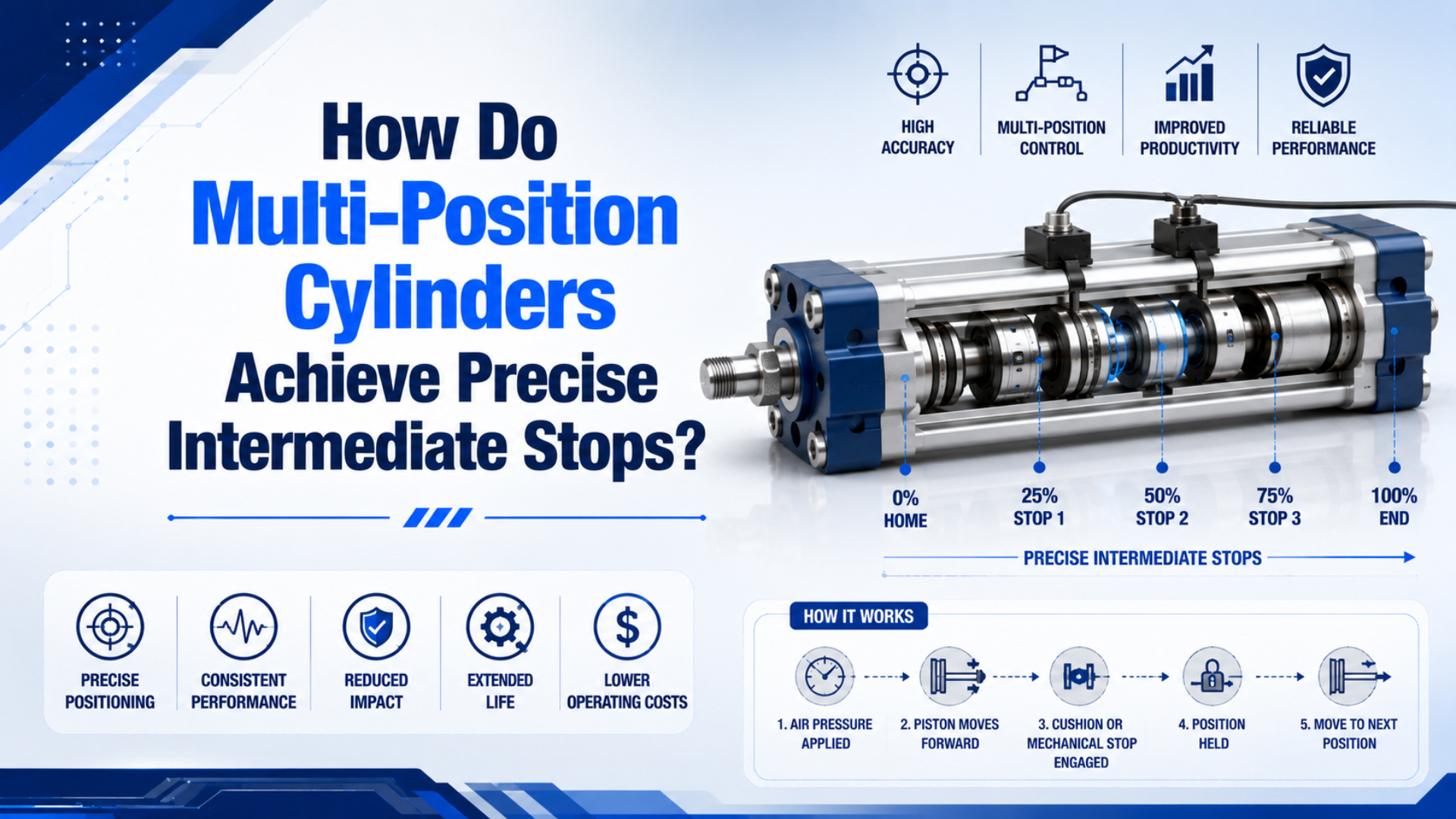
Multi-position cylinders achieve precise intermediate stops by combining two or more fixed pneumatic strokes with mechanically defined end positions. Valve sequencing selects which stage extends, while switches confirm that the commanded position was reached. A sensor alone does not stop the load, and arbitrary programmable positions require a closed-loop positioning system.
Festo describes a common arrangement as two separate cylinders with piston rods moving in opposite directions. Equal strokes create three distinct positions; unequal strokes create four. Parker uses the term duplex cylinder for a similar back-to-back configuration and distinguishes it from a tandem cylinder, whose pistons share a rod to increase force (Festo multi-position cylinders; Parker engineering data, accessed July 18, 2026).
Key Takeaways
- Hard stops define the discrete positions; valves select them and sensors verify them.
- Equal back-to-back strokes provide three unique positions, while unequal strokes can provide four.
- SMC publishes ±0.02 mm intermediate-stop repeatability for one RZQ series configuration, not for multi-position cylinders in general.
- A rod lock holds a position; a servo loop creates programmable positions.
The useful design question is not simply “How many positions?” It is “What physical feature defines each position, and what happens if air pressure, payload, or valve state changes?” Once that is answered, the roles of the cylinder, valve, sensor, guide, and holding device become much easier to specify.
What Actually Creates the Intermediate Stop?
A multi-position cylinder is a pneumatic actuator with more than two mechanically defined working positions. In a conventional design, each piston travels to an end position inside a staged or duplex assembly. The controller does not estimate a point halfway along one free stroke; it commands a combination of completed strokes that adds up to the required location.
This distinction separates four architectures that are often grouped under the same marketing label:
| Architecture | Available positions | What defines the stop? | Can positions change by software? |
|---|---|---|---|
| Back-to-back cylinders with equal strokes | 3 | Cylinder end positions and the shared mounting arrangement | No |
| Back-to-back cylinders with unequal strokes | Up to 4 | Two different fixed stroke lengths | No |
| Integrated multi-stage cylinder | Model-dependent fixed positions | Internal stage shoulders or metallic stops | No |
| Servo-pneumatic axis | Many commanded positions | Feedback loop controlling measured position | Yes, within system limits |
The vocabulary matters during purchasing. Parker describes a duplex cylinder as two cylinders in line with pistons that are not connected, generally used for three-position operation. A tandem cylinder has pistons connected to a common rod and is intended to increase output force. Treating those terms as interchangeable can produce the wrong actuator even when the bore and total length look correct (Parker engineering data, accessed July 18, 2026).
How Do Three- and Four-Position Cylinders Sequence Their Strokes?
For a two-stage arrangement, let the available strokes be and . The commanded position can be written as:
where:
- is the resulting position measured from the chosen datum;
- and are the fixed strokes of stages A and B;
- and are valve-controlled stage states, each either retracted or extended.
The logic produces four state combinations:
| Stage A | Stage B | Nominal position | Result |
|---|---|---|---|
| Retracted | Retracted | Home position | |
| Extended | Retracted | First intermediate combination | |
| Retracted | Extended | Second intermediate combination | |
| Extended | Extended | Full combined travel |
When , the two middle combinations lead to the same nominal location, so there are three unique positions. When and differ, the combinations can create four unique positions. The machine designer must still confirm how the selected product is mounted, because Festo notes that fixing one rod end can make the cylinder barrel move and may require flexible tubing and cable connections.
An integrated three-position cylinder may use a different port sequence. For example, SMC’s RZQ instructions show a specific pressure sequence for first-stage extension and full extension. That sequence belongs to the RZQ design; it should not be copied to another cylinder without its circuit diagram (SMC RZQ catalog, accessed July 18, 2026).
What Does “Precise” Mean for an Intermediate Stop?
Precision is not one universal catalog number. Repeatability is the spread of measured stopping positions across repeated cycles under stated conditions. A useful specification also separates position accuracy, overrun, and holding stability. A mechanism can repeatedly contact the same internal stop yet still be offset from the nominal machine coordinate because of mounting tolerance, frame deflection, or datum setup.
SMC publishes intermediate-stop repeatability of ±0.02 mm or less for its RZQ three-position cylinder and attributes that result to metallic components pressing together at the intermediate position. That is strong model-specific evidence, but it is not a generic rating for every bore, stroke, load, speed, or multi-position architecture.
The same SMC document also gives two cautions that are more important than the headline value:
- During some transitions, the cylinder may pass the intermediate position and return to it, so the machine must allow for overrun.
- If very tight end-position repeatability is required, SMC advises an external stopper because the internal stopper can displace under pressure and external force.
A catalog repeatability value answers “Does the actuator return to its internal reference?” It does not automatically answer “Will the tool center point land within tolerance?” The second question includes guide clearance, bracket stiffness, payload moment, temperature, impact energy, pressure during motion, and how the machine coordinate is calibrated.
Use the following acceptance-test definition instead of the word precise alone:
| Requirement | What to specify or measure |
|---|---|
| Accuracy | Maximum error from the machine’s commanded coordinate |
| Repeatability | Spread across repeated approaches under defined conditions |
| Approach direction | Whether the point is reached from one direction or both |
| Overrun | Maximum travel beyond the target during switching |
| Settling time | Time from command until position remains inside the allowed band |
| Holding stability | Allowed drift while the load dwells at the position |
For long tools, offset loads, or slide tables, use an external guide and verify the moment load separately. Cylinder seals and piston bearings are not substitutes for a machine guide. If you need an initial force estimate before checking dynamic behavior, use the pneumatic cylinder force calculator and then apply the product manufacturer’s load, speed, and guiding limits.
Why Don’t Sensors or a Closed-Center Valve Create a Precise Stop?
A magnetic cylinder switch is normally a confirmation device. It changes state when the piston magnet enters its sensing window, allowing the PLC to confirm a position, detect a timeout, or sequence the next operation. It does not absorb the moving load’s energy or create a rigid mechanical datum.
Festo’s ADNM documentation illustrates this separation: the actuator provides multiple mechanically defined positions, while proximity switches are optional for position sensing. Available sensing locations also depend on the cylinder size and configuration, so the sensor plan must be checked against the selected model rather than assumed from a generic drawing (Festo ADNM documentation, accessed July 18, 2026).
Trapping air with a closed-center directional valve is also not equivalent to a hard stop. Compressed air stores energy, seals and valves leak, temperature changes pressure, and an external force can compress one chamber while expanding the other. Festo’s pneumatic safety guidance notes that trapped air does not directly guarantee standstill and that overtravel depends on speed and moving mass (Festo pneumatic safety engineering guide, accessed July 18, 2026).
That does not make a closed-center circuit useless. It can reduce motion or provide a short process pause in a properly assessed application. It simply should not be credited as the sole position reference or personnel-protection measure.
When Do You Need a Rod Lock, Brake, or Closed-Loop Servo System?
A rod lock is a holding device that clamps a stationary piston rod under its rated conditions. It is not automatically a dynamic brake or a positioning system. Use each holding or control device according to the job it must perform, because a rod lock, a brake, and a servo loop solve different problems even if each can leave the actuator between its end caps.
| Need | Appropriate starting architecture | Critical limitation |
|---|---|---|
| Two to four repeatable fixed positions | Multi-position or duplex cylinder | Positions are hardware-defined |
| Hold a stopped vertical load during air loss | Rated rod lock or mechanical holding device | Static holding rating is not a positioning rating |
| Arrest a moving load | Purpose-rated brake, stop, or engineered deceleration system | Check kinetic energy and stopping distance |
| Many recipes or changing target positions | Servo-pneumatic or electric axis | Requires feedback, control, tuning, and commissioning |
| Personnel safety function | Risk-assessed safety architecture | A standard valve or switch alone is insufficient |
Parker’s P1F cylinder documentation explicitly separates locking from positioning: its locking unit is intended to hold a stationary rod and is not suitable as the device that repeatedly positions a moving cylinder. That boundary prevents a common failure mode—using a static clamp as a dynamic brake (Parker P1F ISO cylinder catalog, accessed July 18, 2026).
For the mechanical and safety boundary in more detail, see our cylinder rod-lock guide.
When targets must change from the HMI, use feedback-based positioning. Enfield describes its S2 as a system combining a proportional valve, sensors, and embedded control electronics for unlimited mid-stroke positions and motion profiles. That is a system-level capability, not a property of a bare cylinder (Enfield S2 positioning system, accessed July 18, 2026).
For a deeper comparison of feedback control, see our guide to servo-controlled pneumatic positioning. If the application needs many coordinated positions, low settling time, and stored motion profiles, also compare it with an electric actuator before fixing the machine architecture.
What Should Be Included in a Multi-Position Cylinder RFQ?
A useful RFQ defines the machine behavior before naming a cylinder series. That gives the supplier enough information to separate a fixed multi-position solution from a guided slide, rod lock, servo-pneumatic system, or electric axis.
Include:
- every required position measured from one stated datum;
- whether each position is approached from one direction or both;
- allowed accuracy, repeatability, overrun, settling time, and dwell drift;
- moving mass, external force, payload moment, orientation, and center of gravity;
- required stroke time, cycle sequence, and expected cycles per shift;
- point-of-use pressure during motion, available flow, tube length, and valve location;
- whether the load must remain held after an emergency stop or air loss;
- external guide, stopper, shock absorber, and cushion arrangement;
- sensor type, required diagnostic coverage, and PLC interface;
- temperature, contamination, washdown, corrosion, and lubrication conditions;
- the applicable machine risk assessment and validation criteria.
ISO 4414 provides general rules and safety requirements for pneumatic fluid power systems, but compliance still depends on the complete machine and its intended use—not the cylinder alone (ISO 4414:2010, accessed July 18, 2026).
In our experience, the fastest way to reject an unsuitable concept is to ask whether the intermediate coordinate is allowed to change after commissioning. If the answer is no, hard-stop multi-position pneumatics may be simple and repeatable. If the answer is yes, the project is a motion-control problem and should be specified as one.
FAQs About Multi-Position Cylinders
These questions resolve the most common specification errors: confusing a sensed position with a mechanically defined one, treating a holding lock as a brake, and expecting fixed-stroke hardware to behave like a programmable servo axis. The correct choice depends on how the target is defined and what must happen during a fault.
Can a standard cylinder stop accurately in the middle of its stroke?
Not reliably with an ordinary on/off valve and no external position-defining hardware. A standard cylinder is most repeatable at its end stops. For a middle position, use a multi-position cylinder, an external hard stop, or a closed-loop positioning system selected for the required accuracy, load, and speed.
Why do equal strokes create three positions but different strokes create four?
Two stages provide four retracted/extended state combinations. If both strokes are equal, the two single-stage-extended combinations produce the same nominal displacement, leaving three unique positions. With unequal strokes, those two combinations produce different displacements, so all four states can correspond to distinct positions.
Does a magnetic sensor hold the cylinder at an intermediate position?
No. A magnetic sensor reports that the piston entered its sensing region; it does not create a stop or resist the payload. The actual position must be defined by a mechanical stop or controlled by a feedback loop. Use the sensor for confirmation, sequencing, diagnostics, and timeout detection.
Can a rod lock stop a moving cylinder safely?
Do not assume it can. Many rod locks are rated to hold a stationary rod and are not intended for repeated dynamic braking. If the load may be moving when the device acts, specify a purpose-rated brake or engineered stopping system and verify energy, stopping distance, load direction, and safety performance.
When should I choose servo pneumatics or an electric actuator?
Choose a controlled axis when positions change by recipe, motion profiles matter, or measured feedback is required. Servo pneumatics can suit compliant, fast motion with available plant air. Electric actuation is often easier to commission when the machine needs many positions, coordinated motion, logged position data, or tight settling behavior.
Sources and technical references
- Festo Multi-position Cylinders, three- and four-position back-to-back cylinder architecture. Retrieved July 18, 2026.
- Festo ADNM Multi-position Cylinder Documentation, position range and proximity-switch sensing provisions. Retrieved July 18, 2026.
- Parker Engineering Data, duplex, three-position, and tandem-cylinder distinctions. Retrieved July 18, 2026.
- SMC RZQ Three-position Cylinder Catalog, model-specific intermediate-stop repeatability, port sequence, overrun, and stopper cautions. Retrieved July 18, 2026.
- Parker P1F ISO Cylinder Catalog, rod-lock holding and positioning limitations. Retrieved July 18, 2026.
- Enfield Technologies S2 Positioning System, proportional valve, sensor, and controller architecture for programmable positions. Retrieved July 18, 2026.
- Enfield Technologies video, feedback-controlled rodless cylinder positioning demonstration. Retrieved July 18, 2026.
- ISO 4414:2010, general rules and safety requirements for pneumatic fluid power systems. Retrieved July 18, 2026.