

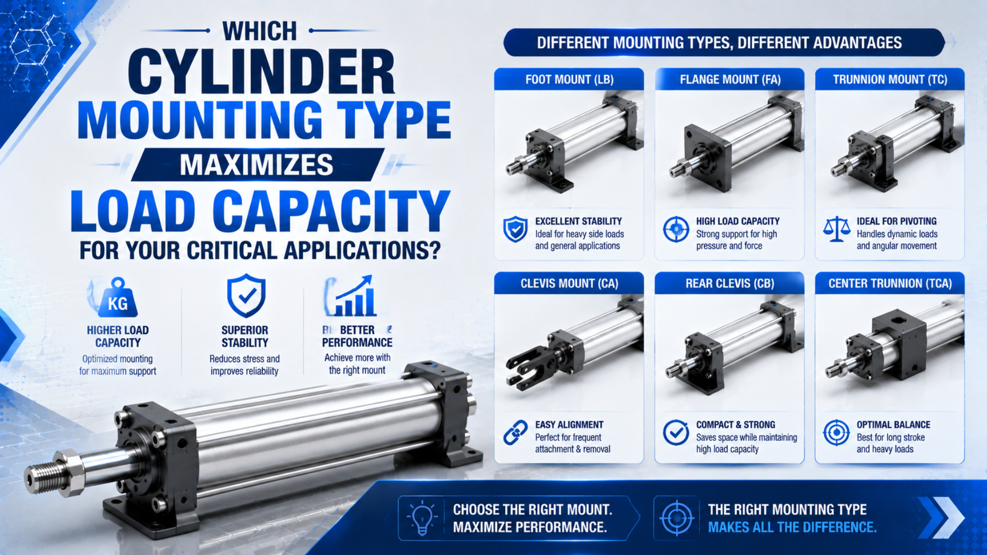
No cylinder mounting type provides the highest load capacity in every application. A centerline flange can transfer straight thrust efficiently, a clevis or trunnion can follow an arc, and a foot mount can fit an offset machine frame. The correct choice is the one whose motion and load path match the machine, with every component checked against its own rating.
That distinction matters in critical equipment. The cylinder produces axial force, but the mount, rod end, pins, fasteners, bracket, guide, and supporting structure must carry the resulting reactions. The safe application limit is the lowest verified limit in that chain, not a generic number assigned to the mount name.
Cylinder thrust is the axial force created by the effective pressure acting on piston area. Mount reaction is the force and moment transferred from the cylinder into its support. Load path is the complete route those reactions follow through accessories, pins, fasteners, brackets, guides, and the machine frame.
Key Takeaways
- ISO 15552 covers detachable-mount cylinders from 32 to 320 mm at up to 10 bar, but it does not rank mounting styles by universal load capacity.
- Choose fixed or pivot mounting from the real motion path.
- Verify the cylinder, accessory, rod, guide, fasteners, bracket, and frame separately.
Publisher information is available on the About Us page. Send technical questions or correction requests through Contact.
The Mount Does Not Set Cylinder Force
ISO 15552 defines basic, mounting, and accessory dimensions for detachable-mount pneumatic cylinders with 32 to 320 mm bores and a maximum rated pressure of 1,000 kPa, or 10 bar. It standardizes an interface envelope for interchangeability, not one allowable force for every flange, foot, clevis, or trunnion (ISO 15552:2018, confirmed 2025).
The pressure-generated extension force starts with piston area:
For retraction, the piston rod reduces the effective area:
Here, is force in newtons, is the effective pressure difference across the piston in pascals, is bore diameter in metres, and is rod diameter in metres. Seal friction, guide friction, opposing-chamber pressure, acceleration, linkage angle, and pressure loss reduce the force available to the load.
Changing from a rear flange to a rear clevis doesn’t increase piston area. It changes how the cylinder body reacts that force into the frame. Before comparing mounts, estimate push and pull force with the cylinder force calculation method and keep the result separate from bracket and guide ratings.
In our experience, a useful design boundary is: the cylinder force calculation supplies an input to the mount review; it is not the mount rating. If a cylinder can theoretically generate 5 kN, that doesn’t prove that its accessory, pivot pin, machine bracket, or extended rod can safely transmit 5 kN under the proposed duty.
Start With the Motion Path
Parker groups standard cylinder mountings into three force-transfer families: fixed mounts that react force on the cylinder centerline, pivot mounts that permit alignment change in one plane, and fixed mounts that react force away from the centerline. That three-family model is more useful than ranking mounts by nominal newtons (Parker Mounting Information, 2025).
Draw the load path at the retracted, mid-stroke, and extended positions. Does the driven connection stay on one straight, externally guided line? Does it swing through an arc? Does the machine base sit below or beside the cylinder axis? These questions decide the mounting family before bore size or bolt pattern enters the discussion.
| Actual machine motion | Mounting family to investigate | Main engineering check |
|---|---|---|
| Straight, guided translation | Fixed centerline, such as front or rear flange | Keep the major reaction close to the cylinder axis and control alignment |
| Straight motion from an offset base | Fixed non-centerline, such as foot or side mount | Resolve the eccentric reaction and resulting frame moment |
| Arc in one defined plane | Rear clevis, eye, or trunnion pivot | Keep pivot axes parallel and free through the full travel |
| Out-of-plane angular change | Rated spherical joint or redesigned mechanism | Verify angular limit and prevent the rod from becoming a universal joint |
| Payload with lateral force or overturning moment | External guide plus a suitable cylinder mount | Carry side load and moment in the guide, not the piston rod |
A pivot mount accommodates the intended angular motion. It does not turn a cylinder into a linear guide. If the payload imposes lateral force or overturning moment, use a rail, bearing, guided cylinder, or rodless actuator with documented guide ratings. The side-load mitigation guide covers that separate failure path.
Fixed mounting also needs measured alignment. A rigid flange can transfer straight thrust well, but it can force the rod and bearing to absorb assembly error if the load connection and guide are over-constrained. Use the mounting and alignment acceptance workflow after the mounting family is selected.
How the Main Mounting Families Change the Load Path
Parker’s mounting guide identifies centerline fixed mounts as the preferred group for straight-line force transfer and lists six pivot variants for curved motion in one plane. The guide also warns that stroke, rod diameter, push or pull duty, and the load connection remain part of mount selection (Parker Mounting Information, 2025).
Front and rear flange mounts
A flange can place the mounting reaction close to the cylinder centerline. Rear flanges are commonly evaluated for major push duty, while front flanges can suit major pull duty, but the exact recommendation must come from the configured cylinder catalogue. The machine plate still needs enough stiffness, locating accuracy, edge distance, and fastener capacity.
Don’t infer strength from flange area alone. The flange-to-cylinder connection, bolt circle, pilot, plate thickness, welds, and frame deflection can each become the limiting element. A large bore only raises the possible piston force; it doesn’t upgrade the surrounding structure.
Foot and side mounts
Foot and side mounts are useful when the machine base is offset from the cylinder axis. That offset also creates a turning moment in the mounting system. Parker recommends suitable keys or dowels for major loads on side-mounted cylinders while avoiding restraint that prevents normal expansion and contraction.
These mounts can be reliable when the machine frame is designed for the eccentric reaction. They are a poor shortcut when a thin plate is expected to hold the cylinder axis under reversing load. Measure loaded deflection rather than judging the bracket by appearance. For overhung geometry, the cylinder deflection guide separates transverse bending from axial rod stability.
Clevis, eye, and spherical pivot mounts
A rear clevis or eye provides a body pivot for mechanisms that sweep through an arc. The rod end normally needs a matching pivot, and both pin axes must remain parallel unless a rated spherical arrangement is deliberately used. Pin shear, bearing pressure, lug bending, clearance, lubrication, and retention all need drawings and ratings.
A spherical bearing can accommodate limited angular deviation, but its catalogue angle is not permission for uncontrolled multi-axis motion. Check the exact bearing, pressure, bore, and accessory combination. If the mechanism path is poorly defined, solve the kinematics before selecting a larger joint.
Trunnion mounts
A trunnion creates a transverse pivot axis on the cylinder body. Head, cap, and intermediate positions change the supported mass, swing envelope, rod stability, and bearing reactions. The pins should work in supported shear rather than bending, and both bearing blocks must be coaxial.
Trunnions do not provide continuous 360-degree rotation. They allow the cylinder to swing about one defined axis through the mechanism’s required arc. The trunnion mount application guide covers position selection, pin support, force angle, and commissioning in detail.
What Actually Limits the Allowable Load?
ISO 8140 specifies interchangeable dimensions for rod-end clevises used with 10 bar pneumatic-cylinder series and states that their design is based on maximum forces from the applicable bore and pressure. That still does not rate an entire installed axis; the machine-side bracket, pin support, rod, and frame remain separate design responsibilities (ISO 8140:2018).
Treat the application as a chain of rated elements. The allowable operating condition is bounded by the first element that reaches its documented limit:
-
Configured cylinder: Verify bore, rod diameter, pressure rating, stroke, seals, cushioning, ports, sensors, and the manufacturer’s force data.
-
Mounting accessory: Confirm its exact part number, compatible bore and series, permitted location, fasteners, and any load or pressure restriction.
-
Rod-end connection: Check thread engagement, clevis or eye rating, pin shear, bearing pressure, retention, angular travel, and lubrication.
-
Piston rod: Review compressive buckling for push duty, especially at long stroke. The rod buckling calculator is a screening aid; the configured manufacturer’s chart remains controlling.
-
External guide: Verify lateral force, pitch, yaw, and roll moment against the guide’s own load-versus-life data.
-
Machine structure: Calculate bracket bending, bolt tension and shear, weld stress, bearing stress, frame deflection, and fatigue under the real duty cycle.
-
Dynamic stop: Check moving mass, speed, cushion energy, external stop reactions, and shock. Mounting hardware can see a much higher transient reaction than the steady process force.
For an offset transverse force, the basic moment relationship is:
Here, is moment in newton-metres, is transverse force in newtons, and is the perpendicular distance in metres from the reaction point to the reference axis. Compare each force and moment with the exact component’s catalogue method. Don’t combine axial load, side load, and moment in a homemade interaction equation unless the manufacturer publishes that equation or an interaction curve.
From our work, the practical capacity of the installed axis is better expressed as a decision rule than a universal formula: approve the duty only when every named component has documented margin under the same load case. This forces the review to identify the actual weak link instead of hiding it inside one value called “mount capacity.”
Worked Example: The Same Cylinder, Three Different Reactions
SMC’s air-cylinder selection material tabulates different maximum strokes for buckling according to cylinder size, operating pressure, and mounting style, including foot, flange, clevis, and trunnion arrangements. The table demonstrates why a mount changes stability conditions even when the pressure-generated piston force remains the same (SMC Air Cylinders Model Selection, 2026).
Consider an illustrative 80 mm bore cylinder extending at an effective pressure difference of 0.6 MPa. Ignoring friction for the theoretical first step:
The theoretical extension force is about 3.02 kN. That number doesn’t change when the same cylinder body moves between approved flange, foot, and pivot configurations. The reactions do change:
- Rear flange, straight guided load: The major reaction can remain close to the cylinder axis. Check flange bolts, plate stiffness, alignment, and rod compression.
- Foot mount below the axis: The same axial force enters the frame through an offset mounting plane. The feet, locating method, bolts, and base now resist an additional turning moment.
- Rear clevis driving a lever: The cylinder changes angle through the stroke. Check both pivot pins, lug bearings, force angle, hose movement, swing clearance, and extended-rod stability.
Suppose a tooling offset also applies a 400 N transverse reaction 0.20 m from the guide reference. The resulting moment is:
That 80 N m belongs in the guide and structure review. Selecting a clevis does not make the piston rod a suitable carrier for it. This is why critical applications need separate force, moment, buckling, and structural checks even when the bore and pressure are already known.
A Six-Step Selection Workflow for Critical Applications
Festo’s 2026 DSBC catalogue covers seven bores from 32 to 125 mm, strokes from 1 to 2,800 mm, and a range of foot, flange, clevis, swivel, and trunnion accessories. Its option matrix also contains combination restrictions, showing that even one modular cylinder family needs configuration-specific checks (Festo DSBC catalogue, 2026).
-
Freeze the motion geometry. Record retracted, mid-stroke, and extended coordinates; the pivot plane; guide datum; offsets; and possible frame deflection. Decide whether the body must stay fixed or follow an arc.
-
Calculate the force envelope. Use the lowest credible pressure at the cylinder, both motion directions, gravity, process force, acceleration, friction, back pressure, linkage angle, and abnormal but foreseeable conditions.
-
Resolve the reactions. Draw axial force, transverse force, moment, pin reactions, bolt loads, and support reactions for the governing positions. Keep steady process force separate from stopping or shock loads.
-
Select exact configured parts. Match the cylinder code, mount kit, rod-end accessory, pins, bearings, fasteners, guide, and cushion or shock absorber. A matching bolt pattern is not evidence of equivalent capacity.
-
Check every limit. Review pressure, thrust, rod buckling, accessory restrictions, pin and lug stress, bolt and bracket strength, guide moments, frame deflection, fatigue, speed, and end-of-stroke energy.
-
Commission against recorded acceptance criteria. Isolate stored energy before work, verify alignment through the stroke, pressurize gradually, run at reduced speed, then confirm production load, timing, cushioning, fastener condition, leakage, and sensor operation.
For high-speed or high-mass axes, use the end-of-stroke force and energy workflow before approving the mount. A static force calculation cannot predict the reaction created when the moving assembly stops.
Our team found that the most revealing drawing is often not the cylinder datasheet. It is the machine free-body diagram at the least favorable stroke position. That drawing shows whether the selected mount follows the mechanism or merely fits the available holes.
What Belongs in the RFQ and Design Review?
ISO 15552 standardizes a 32 to 320 mm, 10 bar dimensional series, but it leaves manufacturers freedom over many construction and option details. An RFQ for a critical mounted cylinder therefore needs the configured drawing and actual load cases, not just “ISO cylinder, 80 mm bore, flange mount” (ISO 15552:2018, confirmed 2025).
| RFQ field | Information to provide | Why it changes the mounting review |
|---|---|---|
| Cylinder duty | Bore, rod, stroke, push or pull, pressure range, speed, cycles, cushioning | Defines force, stability, fatigue, and stopping conditions |
| Motion geometry | Fixed or pivoting body, coordinates at three positions, angle range, offsets | Selects the mounting family and governing load case |
| Payload and process | Mass, centre of gravity, external force, acceleration, shock, gravity direction | Resolves axial, transverse, moment, and dynamic reactions |
| Guide arrangement | Rail or bearing type, spacing, moment ratings, floating connection | Shows which component carries side load and controls motion |
| Mount details | Accessory code, position, pin and bolt sizes, pilots, keys, tightening data | Establishes the real interface instead of a generic mount label |
| Machine structure | Material, plate thickness, welds, supports, allowable deflection | Verifies the frame behind the cylinder mount |
| Environment | Temperature, corrosion, washdown, dust, chemicals, lubrication access | Changes materials, seals, coatings, bearing, and maintenance needs |
| Acceptance | Alignment readings, force or pressure test, speed, leakage, cushion, inspection points | Makes the selected arrangement verifiable on the machine |
Ask the supplier to return an option-specific drawing, compatible accessory codes, installation instructions, rating data, and stated exclusions. If the same body will use several approved mount kits, the multi-mount actuator platform guide explains how to control those variants without assuming every kit is equivalent.
A useful design-review question is: which drawing owns each limit? The cylinder supplier owns configured product ratings, the guide supplier owns guide loads and moments, and the machine designer owns brackets, fasteners, welds, and frame stiffness. If a limit has no named owner or source drawing, it has not been verified.
The Selection Rule That Prevents False Capacity Comparisons
Parker’s three mounting groups distinguish centerline fixed, pivot, and non-centerline fixed force transfer, while ISO 15552 covers dimensional interchangeability across 32 to 320 mm bores at up to 10 bar. Together they support one clear rule: select by motion and load path, then verify the exact configuration (Parker; ISO).
For straight, well-guided motion, start with a fixed centerline arrangement. For an arc in one plane, investigate a clevis, eye, or trunnion arrangement. For an offset base, calculate the eccentric reaction before approving a foot or side mount. In every case, use an external guide for transverse payload loads and verify the weakest component under the governing duty.
There is no honest “maximum-load mount” without a cylinder model, pressure, stroke, force direction, speed, motion path, mounting accessory, rod-end connection, guide, bracket, and frame. Once those inputs are defined, the answer becomes specific and auditable.
Cylinder Mounting FAQs: What Should Engineers Verify?
ISO 15552 covers detachable-mount cylinders from 32 to 320 mm at up to 10 bar, while Parker divides mountings into three force-transfer groups. Those facts explain why engineers should verify a complete load path instead of assigning one universal newton value to each mounting name (ISO 15552; Parker).
Which cylinder mounting type has the highest load capacity?
No mounting family is strongest in every application. Parker identifies three different force-transfer groups, each suited to different geometry. A centerline flange can transfer straight thrust efficiently, while a pivot mount suits an arc. Compare exact cylinder, accessory, pin, fastener, bracket, guide, and frame ratings under the same load case.
Can a pivot mount safely carry side load?
A pivot mount permits angular motion about its designed axis; it is not a linear guide. Parker describes pivot mounts as allowing alignment change in one plane. Lateral payload force and overturning moment should normally be carried by an external guide with documented ratings, while the cylinder transmits axial force through the linkage.
Does a trunnion mount rotate through 360 degrees?
No. A trunnion provides one transverse pivot axis, and Parker describes pivot applications as curved travel in one plane. The mechanism may sweep through its required angular range, but the mount is not a continuous rotary union or universal joint. Verify clearance, hose motion, pin support, and the exact catalogue angle.
Can I replace a fixed mount with a pivot mount on the same cylinder?
Only when the cylinder manufacturer approves the exact accessory for that series, bore, option set, and mounting location. Festo’s DSBC catalogue spans seven bores and many accessories but still lists combination restrictions. Recheck installed length, pivot coordinates, rod end, ports, sensors, cushioning, swing clearance, buckling, and machine reactions.
How should I choose a safety factor for a cylinder mount?
Don’t apply one universal factor to every failure mode. Use the factors and allowable values required by the cylinder, accessory, fastener, structural, fatigue, and machine-safety design methods that govern the application. ISO 15552’s 10 bar scope is a cylinder-series rating, not a prescribed structural safety factor for the installed mount.
Sources and technical references
- ISO 15552:2018. Evidence role: bore range, maximum rated pressure, detachable mountings, and dimensional-interchangeability scope. Source type: international standard; confirmed 2025.
- ISO 8140:2018. Evidence role: rod-end clevis mounting dimensions and design basis for forces from compatible 10 bar cylinder series. Source type: international standard.
- Parker Mounting Information. Evidence role: three mounting groups, force-transfer direction, pivot motion, and mounting-selection factors. Source type: manufacturer engineering guide; retrieved 2026-07-19.
- SMC Air Cylinders Model Selection. Evidence role: mounting-dependent piston-rod buckling and maximum-stroke selection. Source type: manufacturer engineering catalogue; retrieved 2026-07-19.
- Festo DSBC catalogue. Evidence role: bore and stroke range, mounting accessories, and option-combination restrictions. Source type: manufacturer product catalogue; 2026.