

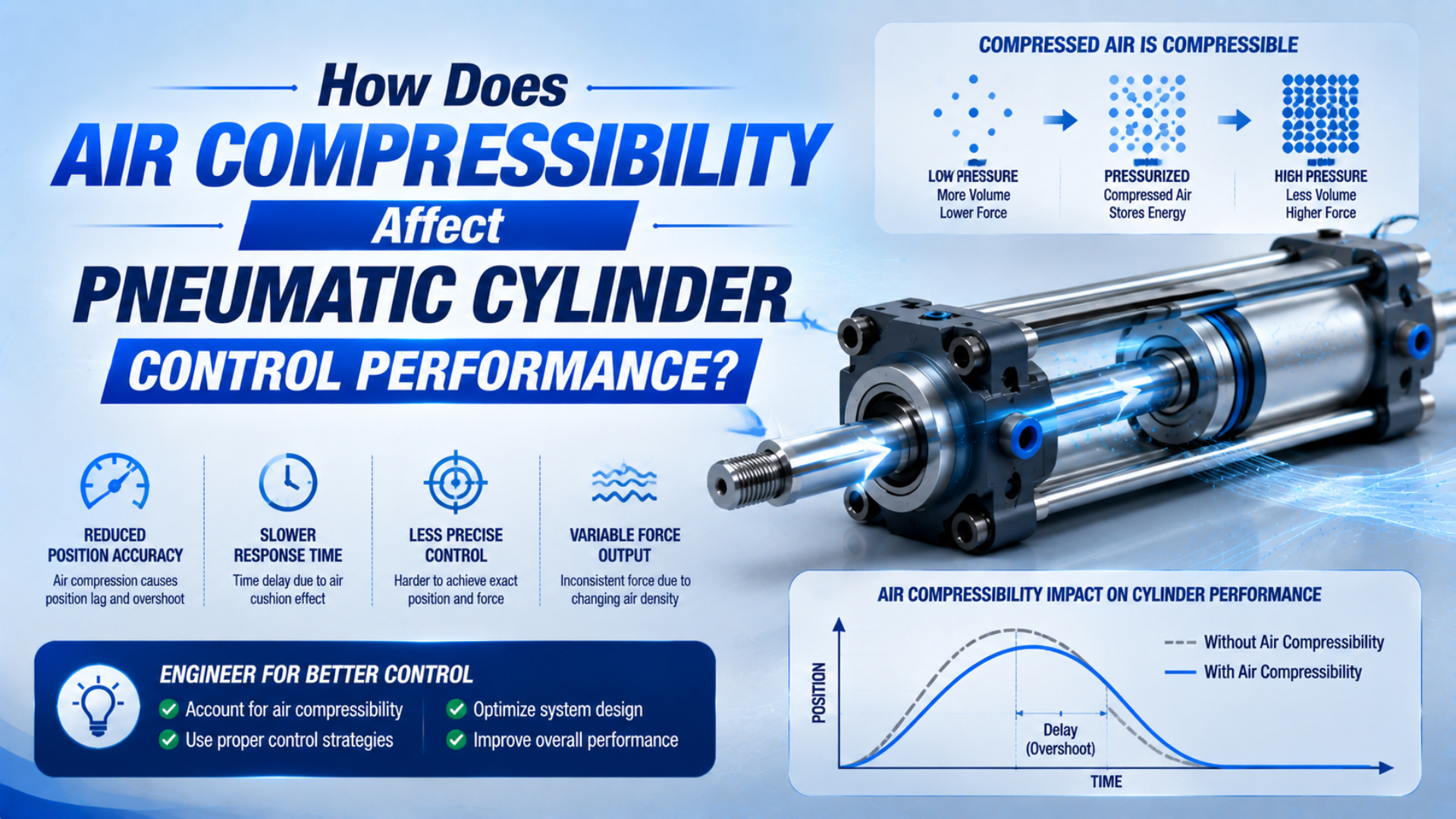
Air compressibility in pneumatic cylinder control makes the actuator behave like a load-dependent spring. It changes how quickly chamber pressure builds, how far an external force can deflect a stopped piston, and how the axis accelerates or settles after a valve command. It does not create one universal positioning error or velocity variation.
The practical consequence is that cylinder control must be evaluated as a system. Chamber volume, absolute pressure, piston position, valve conductance, tubing, moving mass, seal friction, guidance, feedback, and controller tuning all interact. A hard-stop cylinder, a meter-out circuit, and a servo-pneumatic axis therefore have very different performance limits even when they use the same bore and stroke.
Key Takeaways
- Small-signal air stiffness is proportional to absolute pressure and piston area squared, and inversely proportional to trapped volume.
- CAGI recommends no more than 10% pressure drop from compressor discharge to point of use in a well-designed air system.
- Closed-loop control compensates for pneumatic softness; it cannot remove physical compliance, friction, delay, or valve saturation.
What Physical Relationship Makes Compressed Air Behave Like a Spring?
NASA’s ideal-gas reference gives the specific gas constant for air as approximately 287 J/(kg·K) and requires absolute temperature. For a fixed mass of trapped air, pressure rises when volume falls. That pressure change creates a restoring force on the cylinder piston.
The familiar ideal-gas equation is:
Here, is absolute pressure in pascals, is gas volume in cubic meters, is air mass in kilograms, is the specific gas constant, and is absolute temperature in kelvins. Gauge pressure cannot be substituted directly because the gas state depends on pressure measured from absolute vacuum.
A moving cylinder is rarely perfectly isothermal or perfectly adiabatic. A useful local model represents the compression and expansion with a polytropic exponent :
is constant for the modeled trapped-gas process. For slow changes with enough heat transfer, approaches 1. For rapid changes with little heat transfer, it approaches the ratio of specific heats for air, roughly 1.4. Real cylinder behavior can fall between those limits, so is an assumption to document, not a universal correction factor.
Differentiating the polytropic relationship around one operating point gives:
This is a pressure-volume relationship, not yet a linear spring constant. The piston area is needed to convert pressure change into force change and volume change into displacement.
Temperature still matters. For a sealed fixed volume, the ideal-gas law gives . Warming air from 293.15 K to 303.15 K, equivalent to 20°C to 30°C, raises absolute pressure by about 3.4% in that idealized case. A working cylinder exchanges mass and heat, so that percentage must not be promoted into a general positioning error.
How Does Chamber Volume Change Pneumatic Cylinder Stiffness Along the Stroke?
A 2015 study of double-acting pneumatic-cylinder stiffness found that passive stiffness changes along the stroke and that end-position dead volumes are important. The reason is direct: each piston movement changes both chamber volumes, so the two air-spring contributions vary with position and pressure.
For a small piston displacement with a chamber effectively trapped, the linearized stiffness contribution of chamber is:
is chamber stiffness in newtons per meter, is absolute chamber pressure in pascals, is effective piston area in square meters, and is the total trapped chamber, port, fitting, tube, and valve-side volume in cubic meters. The equation describes a small perturbation around a stated operating point.
For a double-acting cylinder with both chambers trapped, the approximate pneumatic stiffness is the sum of both sides:
The cap-end area and rod-end annular area differ on a single-rod cylinder. Chamber volumes and also move in opposite directions as the piston travels. This is why one stiffness number cannot describe the whole stroke.
Consider an illustrative equal-area axis with a 50 mm piston diameter, two 0.25 L trapped volumes, 7 bar absolute pressure in both chambers, and . The calculated total air stiffness is about 28 kN/m. In the idealized linear model, a 100 N disturbance would produce roughly 3.6 mm of displacement before mechanical stiffness, friction, valve leakage, and active control are included.
That example is not an accuracy specification. It shows why the answer must come from configured dimensions and pressures. If tube volume doubles, the affected chamber contribution is roughly halved. If the piston moves and one chamber becomes larger, that side becomes softer while the other generally becomes stiffer.
The same stiffness affects resonance. A first estimate for an axis with effective moving mass and mechanical stiffness is:
is natural frequency in hertz. Because mass, chamber pressures, volumes, piston position, structure, and boundary conditions all enter the calculation, there is no defensible universal frequency range for industrial pneumatic cylinders.
From our analysis, the most useful stiffness value is not a catalog constant. It is a map across the working stroke and load range. That map tells the controls engineer where the axis is softest, where controller gain may become aggressive, and where an external disturbance can create the largest deflection.
Diagnosing Compressibility, Flow, Friction, and Mechanical Faults
A 2026 experimental study measured position, velocity, two chamber pressures, and friction force on three pneumatic cylinders. It found that stick-slip arises from the nonlinear interaction of compressibility, pressure buildup, piston motion, and friction. A position trace alone cannot identify which part of that chain is responsible.
Use synchronized measurements whenever the process tolerance justifies them. At minimum, record the command, both cylinder-port pressures, position, and time. In our experience, these synchronized traces expose the dominant delay faster than changing valves or pressure by trial and error. Add valve feedback, supply pressure, payload, and force when the problem is intermittent.
| Observed symptom | Compressibility-related signature | Competing cause to check | Useful measurement |
|---|---|---|---|
| Stopped piston deflects under changing load | Pressure changes in one or both trapped chambers as position shifts | Guide, frame, coupling, or fixture compliance | Position plus both chamber pressures |
| Long delay before motion | Driving pressure builds while piston remains stationary | Seal breakaway friction, undersized valve, closed flow control | Command, port pressure, and first motion time |
| Overshoot or ringing after a command | Pressure and position exchange stored energy | Controller gain, cushion setting, structural vibration | Position, pressure, valve command, moving mass |
| Low-speed motion jumps | Gradual pressure rise followed by sudden breakaway | Seal stick-slip, dry guide, misalignment | Low-speed position and friction or force estimate |
| Speed falls only during high plant demand | Valve inlet pressure collapses during motion | Branch pressure drop, regulator droop, shared demand | Dynamic pressure before and after the regulator |
| End position varies at a hard stop | Usually not an air-spring positioning issue | Stop wear, rebound, sensor placement, loose tooling | Tool datum, stop contact, and sensor timing |
Pressure lag does not automatically prove that air volume is excessive. A small tube can restrict mass flow, while a large tube adds dead volume. Both can delay pressure response, but they need opposite corrections. This is why tube inside diameter, length, valve conductance, and chamber volume must be reviewed together.
Friction deserves equal attention. The piston can remain still while pressure accumulates, then jump when pressure force exceeds breakaway friction. At very low speed, a larger valve or higher supply pressure may change the jump without solving its cause. The separate guide to meter-out cylinder control explains how exhaust back pressure can damp motion while consuming force margin.
Mechanical guidance is another independent layer. A guided or rodless actuator can resist moment loads and carriage rotation better than an unsupported rod, but the integrated guide does not make the air incompressible. Measure the process at the tooling datum if guide play, frame flex, or payload offset can move the part relative to the cylinder sensor.
Design Changes That Improve Response Without Creating a New Bottleneck
Parker’s cylinder guidance says an undersized tube throttles flow, while an oversized tube adds dead volume, air consumption, and filling time (Parker P1D cylinder guide). The correct design minimizes unnecessary controlled volume while preserving enough conductance for the required mass flow.
Put the control element near the cylinder when response matters
Shortening the distance between a directional or flow-control valve and the cylinder port reduces the volume that must be pressurized and exhausted. Parker also recommends locating a flow-control valve as close to the cylinder ports as piping permits (Parker flow-control instructions).
Don’t reduce tube diameter blindly. If the tube becomes the dominant restriction, chamber pressure may build too slowly even though its internal volume is smaller. Use manufacturer flow data, including sonic conductance or other ISO 6358-1 characteristics, to preselect valves and restrictions. Then measure the dynamic pressure at the ports.
For a target stroke time, the Cylinder Flow Requirement Calculator can establish a first-pass free-air demand. It does not calculate servo bandwidth, trapped-air stiffness, or final positioning accuracy.
Treat pressure as a working-point choice, not a cure
The stiffness equations show that higher absolute chamber pressure raises small-signal pneumatic stiffness when area and volume stay fixed. Yet raising regulator pressure also raises available force, normalized air demand, leakage potential, impact energy, and component loading. It may move the equilibrium point or force the controller to operate in a different valve region.
Select pressure from the load and control requirements. Verify the lowest dynamic pressure that reaches the cylinder during the demanding part of the stroke. If the circuit already has ample force margin, increasing plant pressure to mask poor flow or friction usually adds operating cost without removing the original fault.
Size the bore from force, volume, and valve capacity together
A larger piston area can increase air stiffness, but it also increases swept volume and required flow. With a simple chamber volume approximated by , the ratio becomes approximately . That relationship still leaves load force, rod-side area, dead volume, friction, valve conductance, cushioning, and air consumption to be checked.
There is no general rule that “large bore and low pressure” produces precision or that “small bore and high pressure” produces speed. Oversizing can make pressure response slower when the valve and tube are unchanged. Undersizing can leave too little force margin and make friction a larger share of the available drive force.
Keep supply buffering separate from chamber stiffness
A receiver near a machine can support short peak demand and reduce supply-side pressure sag when it is sized and connected correctly. It does not automatically stiffen the air trapped between a closed control valve and the piston. Connecting extra volume directly to that controlled chamber generally makes the passive air spring softer.
In our experience, drawing the pneumatic circuit twice makes design reviews more decisive. On the first drawing, mark the mass-flow path and every restriction. On the second, mark the gas volume trapped on each side of the piston for every valve state. One explains fill and exhaust speed; the other explains passive compliance after flow is blocked.
Closed-Loop Compensation and Remaining Physical Limits
Festo defines a servo-pneumatic positioning system with three essential elements: a cylinder with displacement encoder, a proportional directional valve, and a position controller. Feedback lets the controller correct measured error, but the controlled axis still contains compressible air and remains physically compliant under external force.
A standard on/off circuit commands valve state. A servo-pneumatic system commands variable flow, measures actual motion, and updates that command. It can compensate for predictable load changes, pressure variation, and state-dependent response within the authority of its valve, sensor, controller, and mechanical system.
That correction has limits:
- Valve saturation: the controller cannot demand more mass flow than the supply path can deliver.
- Deadband and hysteresis: small commands may not create a proportional flow change.
- Sensor limits: resolution, noise, mounting error, and sampling delay affect the measured position.
- Friction: breakaway and stick-slip can create motion that is difficult to correct smoothly.
- Compliance: external force can still displace the piston while the controller builds a counteracting pressure difference.
- Safety state: loss of electrical power or compressed air requires separate load-holding and risk controls.
The complete servo-pneumatic positioning guide covers valve, sensor, and controller selection. For compressibility analysis, the important point is that the plant changes with piston position. A controller tuned near mid-stroke may see different chamber volumes and valve pressure ratios near either end.
Specify control performance with measured terms. Accuracy is closeness to the target, repeatability is the spread of repeated results under stated conditions, resolution is the smallest command or measurement increment, and settling time describes how long the axis takes to remain inside its allowed band. One value cannot substitute for the others.
When Should You Keep Standard Pneumatics, Add Servo Control, or Change Technology?
NIST’s linear-motion metrology work discusses nanometer-order resolution, tens of millimeters of travel, and the measurement uncertainty needed to certify sub-micrometer stages. That is a different problem from an industrial pneumatic axis. Technology selection should start with the measured process tolerance, not a generic accuracy table.
| Required machine result | Starting architecture | Why it fits | What still needs proof |
|---|---|---|---|
| Two end positions against rigid stops | Standard pneumatic cylinder | The stop defines final geometry; air provides motion and force | Impact, stop wear, sensor timing, force margin |
| Stable end-to-end speed | Meter-out or regulated flow circuit | Exhaust control adds damping and adjusts travel rate | Load range, back pressure, first-cycle behavior |
| Several commanded positions or profiles | Servo-pneumatic axis | Feedback and a proportional valve correct measured error | Loaded accuracy, settling time, valve authority |
| Smooth very-low-speed feed | Hydro-pneumatic or specialized low-friction system | Oil metering or purpose-built seals reduce jumpy motion | Temperature, maintenance, controlled stroke zone |
| High static stiffness or tightly coordinated motion | Electric or hydraulic axis | The technology may better match stiffness and synchronization needs | Force, duty cycle, heat, environment, safe state |
Standard pneumatics remain a strong choice when a mechanical stop defines position and the requirement is fast, repeatable two-position motion. Compressibility affects timing, impact, and force buildup, but it does not prevent the tooling from locating against a sufficiently stiff, repeatable stop.
Servo pneumatics make sense when intermediate positions, controlled acceleration, or force regulation justify feedback and commissioning effort. Don’t specify the actuator alone. Specify the complete axis, including valve, sensor, controller, tube route, payload, guide, pressure range, and acceptance test.
Hydro-pneumatic systems deserve consideration when the real problem is smooth low-speed feed or a short high-force work zone. The hydro-pneumatic cylinder guide separates equal-pressure air-hydro control, hydraulic resistance units, and intensifier drives.
Choose an electric axis when high static stiffness, frequent recipe changes, synchronized motion, or tightly controlled profiles dominate the requirement. The tradeoff must include force, duty cycle, installation space, environment, controls skill, maintainability, and total operating cost, not only a catalog repeatability value.
In our experience, the fastest way to narrow the architecture is to ask where position is actually defined. If the answer is “the mechanical stop,” standard pneumatics may be enough. If the answer is “the controller must hold any commanded point under changing load,” the project is a motion-control axis and needs a configured acceptance test.
What Should Engineers Measure Before Changing the Cylinder or Controller?
CAGI’s pressure-drop brief says well-designed compressed-air systems normally keep pressure drop to 10% or less from compressor discharge to point of use. That plant-level limit is useful, but cylinder control requires dynamic pressure measurements at the valve and actuator while the machine is moving.
Collect the following data before changing bore, pressure, valve, or control gains:
- Acceptance result: target position, allowed error, repeatability, settling time, velocity band, or force band.
- Test condition: payload, orientation, center of gravity, approach direction, dwell, cycle count, and temperature range.
- Cylinder geometry: bore, rod diameter, stroke, piston position, cushioning, and estimated end dead volumes.
- Air path: valve model and conductance, fittings, tube inside diameter and length, silencers, and flow-control settings.
- Pressure data: supply before the valve and both cylinder-port pressures during the entire command.
- Motion data: command time, first movement, velocity, overshoot, settling, stop contact, and sensor switching.
- Mechanical condition: guide alignment, side load, frame and fixture stiffness, coupling play, stop wear, and payload movement.
- Control details: sample rate, valve command range, feedback type, resolution, filters, gains, saturation, and in-position logic.
- Abnormal states: first cycle after repressurization, minimum plant pressure, maximum load, loss of signal, and emergency stop.
- Safety measures: stored-energy isolation, suspended-load support, braking, guarding, and restart behavior.
Measure pressure dynamically. A static regulator gauge can look normal even when the valve inlet collapses during acceleration. The guide to air-pressure fluctuations and actuator consistency covers that supply-side diagnosis, while back-pressure troubleshooting addresses the opposing side of the force balance.
Use the measurements to identify the dominant limitation. If pressure reaches the chamber quickly but the piston waits and jumps, investigate friction. If valve inlet pressure collapses, correct supply and distribution. If both pressures respond but the tool datum moves relative to the sensor, inspect guidance and structure. If the axis rings after each correction, review stiffness, mass, valve dynamics, and controller tuning together.
What Is the Practical Control Rule for Compressible-Air Cylinders?
The 2015 double-acting-cylinder study shows that stiffness varies with chamber pressure, volume, and stroke position, while Festo describes servo positioning as a three-part cylinder, proportional-valve, and controller system. The practical rule is to model the operating point, measure the pressure-motion chain, and select control architecture from the process acceptance test.
Air compressibility is neither a defect nor a single error value. It is a physical compliance that can store energy, cushion motion, tolerate overload, and reduce shock. The same compliance can also delay pressure buildup, allow load-dependent deflection, and change the dynamic plant across the stroke.
Start with the two chamber volumes and absolute pressures. Add valve flow, tube dead volume, moving mass, friction, and mechanical stiffness. Then decide whether the machine needs a hard stop, better flow control, a lower-volume circuit, position feedback, or a different actuator technology. That sequence is more reliable than increasing pressure or changing bore by rule of thumb.
Air Compressibility FAQs: What Should Controls Engineers Check?
ISO 6358-1 provides a standardized method for steady-state flow characterization of compressible-fluid components, but it explicitly does not turn a component flow rating into a cylinder accuracy prediction. These answers separate flow capacity, trapped-air stiffness, supply buffering, mechanical guidance, and closed-loop positioning so each can be tested correctly.
Does higher pressure eliminate the effects of air compressibility?
No. Higher absolute pressure increases the linearized air-stiffness term when chamber area and volume stay fixed, but air remains compressible. Raising pressure also changes force, air demand, leakage, impact energy, and component loading. Use the lowest pressure that satisfies the configured load and control requirements with measured dynamic margin.
Do shorter air lines always improve cylinder control?
Shorter valve-to-cylinder lines usually reduce dead volume and can improve pressure response. Tube diameter must still pass the required mass flow. A tube that is too small creates restriction; one that is unnecessarily large adds volume and fill time. Select length, inside diameter, valve conductance, fittings, and target stroke time as one flow path.
Does a local air receiver make the cylinder stiffer?
Not automatically. A local receiver can stabilize supply pressure during a short demand peak. If extra receiver volume is directly connected to a trapped controlled chamber, it increases that chamber’s gas volume and generally lowers passive air stiffness. Treat supply buffering and piston-side trapped volume as two different circuit calculations.
Does an integrated guide solve compressibility-related positioning errors?
No. An integrated guide can resist moment loads, reduce carriage rotation, and keep side loads away from the cylinder’s sealing surfaces. It does not change the thermodynamic compressibility of the air. Measure both the actuator position and the process tooling datum when guide clearance, fixture flex, or payload offset can affect the result.
When is servo-pneumatic control justified?
Consider servo pneumatics when the machine needs commanded intermediate positions, controlled motion profiles, or active compensation for measurable load changes. Specify the cylinder, proportional valve, feedback device, controller, air path, payload, and acceptance test together. If the process instead needs very high static stiffness or coordinated precision motion, compare electric or hydraulic architectures.
Sources and technical references
- NASA Glenn Research Center: Equation of State for an Ideal Gas
- Czmerk: Increasing of Stiffness of Double-Acting Pneumatic Cylinder
- Experimental and System-Level Simulation Study of Stick-Slip Characteristics in Pneumatic Cylinders
- ISO 6358-1: Pneumatic fluid-power component flow characteristics
- Festo: Servo-pneumatic positioning systems
- Parker P1D pneumatic-cylinder guide
- CAGI: Technical Brief on Pressure Drop
- NIST: Ultra-Precision Linear Motion Metrology