

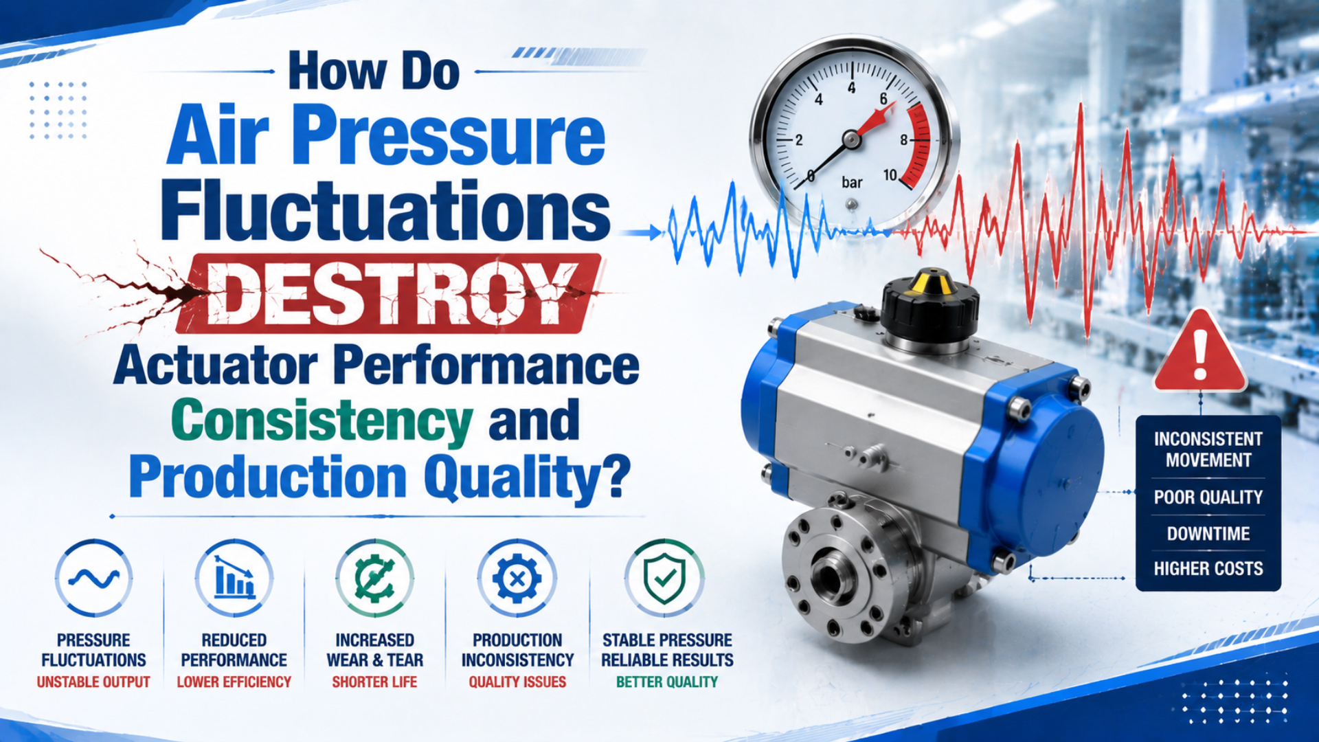
Air pressure fluctuations damage production consistency when the pressure available during the work event falls below the actuator’s force, flow, or cushioning requirement. The consequence isn’t a universal percentage. It can be a weak clamp, late insertion, dropped part, variable impact, or longer stroke time, depending on which margin disappears first.
The useful question is therefore not, “Does the header fluctuate?” It is, “What pressure did the actuator see while the defective part was made?” A static gauge can’t answer that. A cycle-synchronized trace can connect the pressure event to valve command, cylinder motion, process force, and inspection result.
Key Takeaways
- CAGI identifies flow resistance, changing demand, and compressor capacity control as three main fluctuation sources.
- A 63 mm cylinder’s Festo catalog force changes by 280 N between 5 and 6 bar.
- Set pressure limits from measured force and timing margin, not a universal bar tolerance.
For the broader physics of pressure waves and line resonance, see the pneumatic pressure fluctuation guide. This article stays at the production station: how to turn a changing pressure trace into a force-margin decision and a defensible quality acceptance test.
What Pressure Signal Actually Reaches the Actuator?
CAGI identifies three main sources of compressed-air pressure fluctuation: resistance-induced pressure drop, changing air demand, and the compressor’s capacity-control method. Those sources can overlap, so a stable receiver gauge does not prove stable pressure at the actuator port during the work event (CAGI System Design, 2021).
Dynamic actuator pressure is the time-varying pressure measured at the working port during the production event, not the regulator’s static setpoint. Record where it was measured, when it was measured, and what the machine was doing. These five values are not interchangeable:
- Compressor discharge pressure, which reflects package control behavior.
- Receiver or main-header pressure, which shows plant-level supply response.
- Regulator inlet pressure, which reveals the pressure available to the machine.
- Regulator outlet or valve-inlet pressure, which exposes regulator droop under flow.
- Cylinder working-port pressure, which includes valve, fitting, tube, flow-control, and exhaust effects.
A static reading is useful for set-up. It is weak evidence for a fast fault. If the defect occurs during a 200 ms clamp or insertion event, a gauge that an operator reads once per shift cannot show the pressure minimum, recovery time, or oscillation that occurred inside that window.
How Does a Pressure Swing Change Available Cylinder Force?
Festo’s operating data lists 1,400 N at 5 bar and 1,680 N at 6 bar for a 63 mm cylinder, a 280 N catalog-force difference. The example shows why the same pressure change has a larger force consequence as piston area grows (Festo General Operating Conditions, 2022).
For a double-acting cylinder extending against a load, calculate both sides of the piston:
Here, the cap-side and rod-side pressures are the dynamic pressures at the two cylinder ports. Parker warns that multiplying full piston area by a single pressure difference is incorrect for a single-rod cylinder because the cap and annular areas are unequal (Parker Designing With Cylinders, 2024).
If rod-side pressure and friction remain approximately unchanged during a short cap-side pressure change, the ideal change in the cap-side force term is:
The table converts that relationship into an engineering screen. It uses piston area and 1 bar = 0.1 N/mm². Values are ideal cap-side force-term changes, not guaranteed net output.
| Cylinder bore | Force-term change at 0.1 bar | At 0.3 bar | At 0.5 bar |
|---|---|---|---|
| 32 mm | 8.0 N | 24.1 N | 40.2 N |
| 40 mm | 12.6 N | 37.7 N | 62.8 N |
| 50 mm | 19.6 N | 58.9 N | 98.2 N |
| 63 mm | 31.2 N | 93.5 N | 155.9 N |
| 80 mm | 50.3 N | 150.8 N | 251.3 N |
| 100 mm | 78.5 N | 235.6 N | 392.7 N |
The calculation does not prove a defect. It tells you whether the pressure event is large enough to threaten the known process margin. Use the Cylinder Force Calculator to compare measured high and low pressures, then subtract rod-side back pressure, friction, tooling losses, and the required load.
Why Do Quality Problems Appear Before a Cylinder Stops?
Parker’s worked example produces 4,750 lbf on the cap side, 1,000 lbf of opposing rod-side force, and 3,750 lbf net. That 1,000 lbf counterforce illustrates why a cylinder can complete its stroke yet lose enough process margin to seat, grip, press, or cushion inconsistently (Parker, 2024).
A pneumatic axis often has several thresholds. The lowest pressure may still move the unloaded mechanism, but it may not satisfy the production task. Quality can fail at a higher pressure than motion does.
| Application | First margin threatened | Likely production symptom | Evidence to record |
|---|---|---|---|
| Clamp or fixture | Holding force | Part shifts during machining or inspection | Port pressure during dwell, clamp confirmation, part movement |
| Gripper | Frictional grip force | Drop, slip, or surface damage after overcompensation | Grip pressure, part mass, acceleration, jaw state |
| Press or insertion | Available net force | Incomplete seating or variable insertion depth | Pressure, displacement, process force, final inspection |
| Fast transfer axis | Flow and acceleration | Late arrival or inconsistent cycle time | Valve command, position trace, port pressure |
| Cushioned cylinder | Deceleration reserve | Hard impact or variable end-stop shock | Speed before cushion, cap and rod pressure, impact signature |
Pressure alone does not define positioning accuracy. A hard mechanical stop defines final geometry differently from a mid-stroke pneumatic balance or closed-loop servo axis. Remove the claim that every bar of pressure change creates a fixed millimeter error. Measure the actual mechanism and its quality characteristic instead.
Separate Five Pressure Problems Before Changing Hardware
ISO 6953-2:2024 standardizes how pneumatic regulators and filter-regulators are tested and how their main characteristics are presented. That framework matters because set pressure, forward-flow behavior, relief behavior, and hysteresis describe different failure signatures; one word such as “instability” cannot identify the responsible mechanism (ISO 6953-2, 2024).
| Pressure behavior | What the trace shows | Common interpretation | What it is not |
|---|---|---|---|
| Wrong static setpoint | Stable but consistently high or low | Adjustment, reference, or configuration error | A fluctuation |
| Steady flow pressure drop | Difference between two points increases with flow | Restriction or undersized component | Long-term drift |
| Transient sag | Short local pressure minimum during demand | Storage, flow capacity, or simultaneous demand issue | A permanent low setting |
| Hunting or oscillation | Repeated rise and fall around a target | Control interaction, regulator dynamics, or compressor sequencing | Random measurement noise by assumption |
| Drift or creep | Output changes gradually under comparable conditions | Regulator, reference, contamination, temperature, or wear investigation | A millisecond demand event |
The separate pressure-regulator drift guide covers gradual setpoint movement. The pressure-drop troubleshooting guide covers loss between two points under flow. Keep those diagnoses separate before replacing components.
How Should You Capture a Pressure-Quality Event?
SMC’s ISE20 documentation offers response settings from 1.5 ms or less through 5,000 ms and explains that anti-chattering delay can average away a temporary supply drop. The specification proves that sensor configuration changes what a control system can see, so sampling and filtering must match the fault duration (SMC ISE20, 2025).
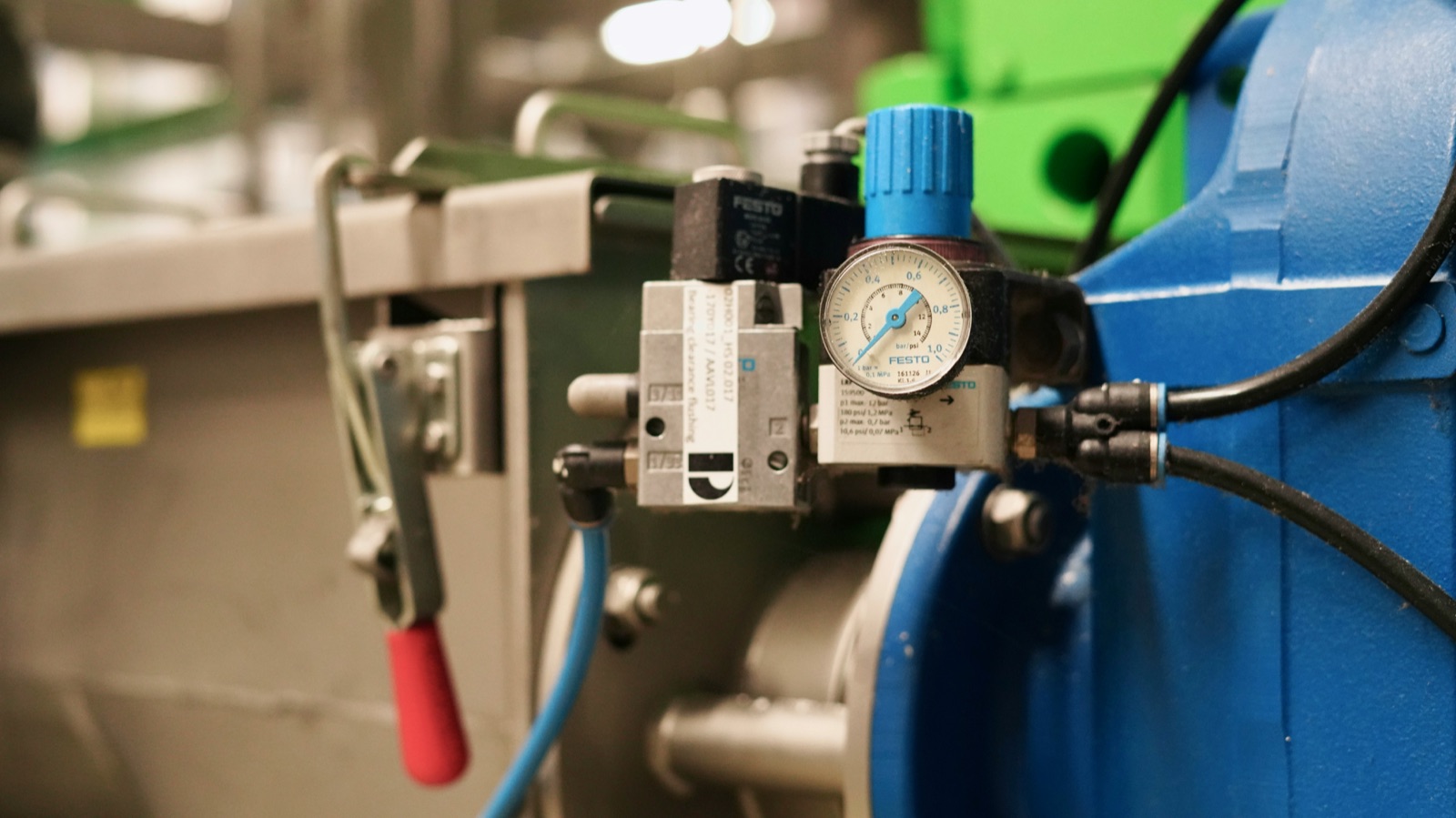 A local gauge confirms the approximate setpoint, but a production fault usually needs a time-synchronized electronic trace. Photo: Paréj Richárd on Unsplash.
Build the measurement around the failed quality event:
- Record the valve command and actuator position on a common time base.
- Measure regulator inlet and outlet pressure to expose supply sag versus regulator droop.
- Add pressure at the relevant cylinder port when the valve-to-actuator path is in question.
- Capture process force, displacement, clamp confirmation, or another direct quality variable.
- Attach the inspection result or defect code to the same cycle record.
- Repeat good and bad cycles at the expected combinations of simultaneous demand.
The pressure minimum is not always the decisive value. Duration matters. A 10 ms dip may be filtered by chamber volume, while a longer sag can reduce pressure throughout the work stroke. Preserve the raw trace before applying display smoothing, debounce, or moving averages that can hide the event you need to diagnose.
Set the Acceptance Band From Force Margin
Festo’s 63 mm table changes from 1,400 N at 5 bar to 1,680 N at 6 bar, while its 100 mm data changes from 3,530 N to 4,240 N. A universal pressure tolerance therefore cannot protect every bore, load, and process; the allowed band must follow required force and measured dynamics (Festo, 2022).
Start with the minimum force required at the tooling, not the nominal regulator setting. Calculate the minimum dynamic net force at the worst measured cap pressure, rod-side back pressure, friction condition, load direction, and tooling efficiency. Then express the force reserve as:
The acceptable value of belongs to the machine risk assessment and process capability plan. In our experience, the useful first screen is the smallest synchronized pressure-force margin inside the work window, not the static regulator setpoint. A fixture that merely locates a part and a gripper carrying a fragile product through high acceleration do not share the same consequence or validation method.
Set at least three acceptance limits:
- A minimum dynamic pressure or force during the work window.
- A maximum recovery time before the next dependent operation.
- A maximum cycle-time or process-output deviation tied to the quality characteristic.
This approach separates an engineering limit from a statistical control limit. A control chart can reveal process movement, but it cannot prove the lowest observed force is mechanically safe or sufficient. Establish the physical margin first, then use production data to monitor whether the process stays inside it.
How Does the Fault Signature Identify the First Restriction?
CAGI recommends no more than 10% pressure drop from compressor discharge to point of use and air velocity of 20 ft/s or lower in distribution piping. Those are system-level design references, not automatic limits for one critical machine branch, which may need a much tighter local allowance (CAGI Pressure Drop Brief, 2022).
| Observed signature | First comparison | Likely investigation path |
|---|---|---|
| Several machines sag together | Header versus compressor discharge | Compressor control, dryer/filter drop, plant demand, main storage |
| One machine sags while header remains stable | Machine inlet versus header | Branch pipe, hose, isolation valve, quick disconnect |
| Regulator inlet stays stable but outlet sags | Regulator inlet versus outlet | Regulator flow characteristic, filter element, setpoint, sizing |
| Valve inlet stays stable but cylinder port sags | Valve inlet versus working port | Valve path, manifold, fittings, tube, flow control, exhaust back pressure |
| Pressure oscillates after demand ends | Time trace at inlet and outlet | Regulator or compressor control interaction, relief behavior, sensor filtering |
| Pressure is stable but quality still varies | Pressure versus force/position result | Load, friction, tooling, alignment, seals, control timing, inspection system |
The last row prevents a common waste of time. Correlation must be demonstrated, not assumed. If the same pressure trace appears on both good and bad parts, pressure is unlikely to be the discriminating cause. Continue with the mechanical, control, or metrology investigation.
For line-volume and valve-location effects, use the pneumatic valve placement guide. For cylinder setpoint and force checks, see the air-cylinder working-pressure guide.
Which Corrections Protect Quality Without Raising Plant Pressure?
DOE gives a rule of thumb near 100 psig: each 2 psi discharge-pressure increase can add about 1.6% to 2% total energy use when 30% to 50% of demand is unregulated. Raising the entire header to mask one weak station can therefore increase plant cost without removing the local cause (DOE Sourcebook, 2003).
Correct the measured cause in this order:
- Restore clogged filters, damaged hoses, leaking connections, and obvious restrictions.
- Resize the branch component with the largest measured dynamic differential.
- Select the regulator from supplier forward-flow, relief, hysteresis, and dynamic data, not port size alone.
- Reduce valve-to-actuator volume where response time is the limiting variable.
- Add local receiver storage only when the demand event and connection path justify it.
- Adjust compressor sequencing or pressure-flow control when the whole distribution system moves together.
- Use electronic pressure control when the process truly requires commanded, closed-loop pressure rather than a fixed mechanical setpoint.
ISO 10094-2:2021 standardizes test methods for electro-pneumatic continuous pressure-control valves. It helps compare supplier data, but it does not promise that an electronic regulator will correct undersized tubing, insufficient upstream pressure, or a valve path that cannot pass the required flow (ISO 10094-2, 2021).
If a short intermittent load needs storage, size it with the actual initial pressure, minimum usable pressure, event duration, and demand flow. The Air Receiver Tank Sizing Calculator is a better starting point than a fixed gallons-per-CFM shortcut. The compressed-air system design guide explains how storage and compressor controls interact.
RFQ and Commissioning Record
ISO 6953-2:2024 applies standardized regulator tests, while ISO 10094-2:2021 does the same for electro-pneumatic continuous pressure-control valves. An RFQ should therefore request the exact test characteristics needed at the operating point instead of asking only for “high precision” or a nominal port size (ISO 6953-2, 2024; ISO 10094-2, 2021).
| Record group | Required information |
|---|---|
| Production task | Part, operation, required force, allowed time, quality characteristic, defect code |
| Actuator | Type, bore, rod diameter, stroke, orientation, load direction, cushion, seal condition |
| Pressure trace | Sensor model, range, accuracy, response/filter setting, location, sample rate, timestamp |
| Air path | Header, branch, filter, regulator, valve, manifold, fittings, tube ID and length, exhaust devices |
| Demand event | Valve command, simultaneous consumers, cycle rate, duration, minimum and recovery pressure |
| Acceptance | Minimum dynamic force/pressure, maximum recovery time, stroke-time limit, inspection result |
| Change control | Part numbers, regulator setting, software revision, drawing revision, test record owner |
Commission the system at the worst credible combination of supply pressure, load, cycle rate, and simultaneous demand. Repeat enough cycles to show the pressure-quality relationship is stable. A single successful stroke proves only that the mechanism moved once.
Publisher and author information is available on the About Us page; use the website contact channel for application details or correction requests.
Pressure fluctuations do not create one universal defect rate. They create risk when the lowest dynamic force, flow, or cushioning reserve crosses a process requirement. Measure that crossing, correct its cause, and preserve the acceptance trace so future maintenance can distinguish recurrence from a different failure.
Air Pressure Fluctuation FAQs
ISO 6953-2 was updated in 2024, and SMC’s ISE20 offers pressure-response settings from 1.5 ms or less to 5,000 ms. Together, those references show why regulator characteristics and sensor timing must be stated explicitly before a pressure fluctuation can be linked to an actuator-quality fault (ISO, 2024; SMC, 2025).
What pressure variation is acceptable for a pneumatic actuator?
There is no universal bar tolerance. Use the minimum dynamic pressure that still provides required net force, stroke time, cushioning, and process capability. Festo’s 63 mm data changes by 280 N between 5 and 6 bar, showing that bore and load margin change the consequence of the same pressure variation (Festo, 2022).
Can pressure fluctuations change cylinder positioning accuracy?
They can change arrival time, seating force, overshoot, and settling behavior, but no universal millimeter-per-bar rule applies. A hard mechanical stop, compliant fixture, mid-stroke balance, and closed-loop pneumatic axis respond differently. Record pressure with position or displacement during the failed cycle, then compare good and defective parts under the same load.
Do pressure fluctuations damage pneumatic cylinders?
Not automatically. Repeated stalls, hard end impacts, inadequate cushioning, unstable loads, or operation outside the product limits can accelerate wear, but the pressure trace alone does not prove damage. Inspect the cylinder, seals, guides, cushions, load alignment, and exhaust path, then compare findings with the manufacturer’s operating and maintenance instructions.
Is a larger receiver always the best solution?
No. CAGI identifies flow resistance, demand changes, and compressor capacity control as three fluctuation sources. Storage helps intermittent demand only when its usable pressure range, volume, location, and connection can support the event. A clogged filter or undersized valve remains a restriction even when a larger receiver is installed (CAGI, 2021).
Where should pressure sensors be installed for troubleshooting?
Start at the regulator inlet and outlet, then add the relevant cylinder working port when the downstream path is suspect. SMC’s selectable response settings start at 1.5 ms or less, so document response time and filtering with sensor location. Synchronize every trace with valve command, actuator position, and the quality result (SMC ISE20, 2025).
Sources and technical references
- Compressed Air and Gas Institute. Compressed Air System Design, Chapter 4. 2021. Retrieved July 17, 2026.
- Compressed Air and Gas Institute. Technical Brief on Pressure Drop. Retrieved July 17, 2026.
- U.S. Department of Energy. Improving Compressed Air System Performance: A Sourcebook for Industry. Retrieved July 17, 2026.
- International Organization for Standardization. ISO 6953-2:2024, Pneumatic pressure regulators and filter-regulators, test methods. 2024. Retrieved July 17, 2026.
- International Organization for Standardization. ISO 10094-2:2021, Electro-pneumatic pressure control valves, test methods. 2021. Retrieved July 17, 2026.
- SMC Corporation. ZSE20(F)/ISE20 Series High-Precision Digital Pressure Switch. Retrieved July 17, 2026.
- Festo. General Operating Conditions, Pneumatic Piston Force Data. 2022. Retrieved July 17, 2026.
- Parker Hannifin. Designing With Cylinders. Retrieved July 17, 2026.