

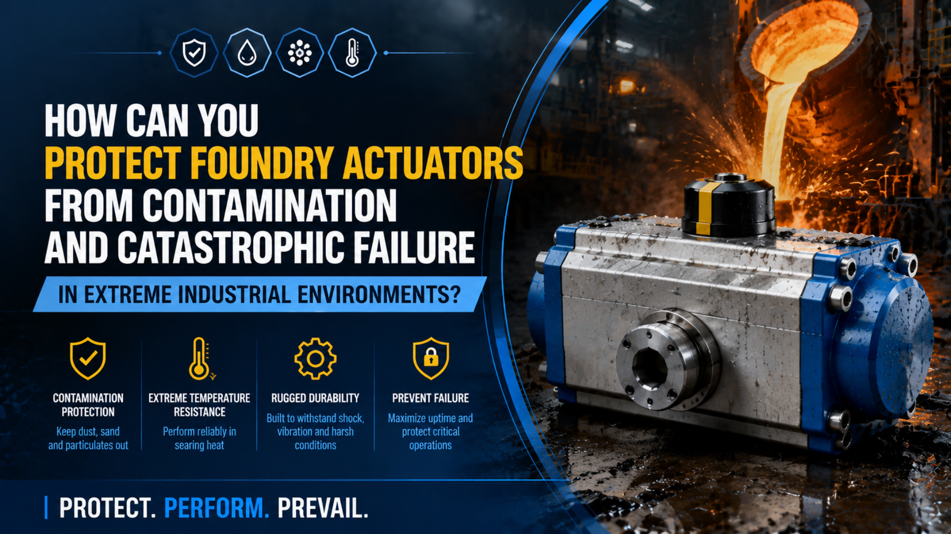
Protect foundry actuators by controlling the exposure path before upgrading the cylinder. In a foundry casting-cleaning study, a NIOSH local-exhaust system reduced respirable-dust exposure by 59% to 77% depending on the tool (NIOSH, 1998). Source capture, shielding, correct wipers, clean compressed air, and verified maintenance form one protection system.
Foundry actuator protection is a system of source control, shielding, contamination-resistant hardware, clean compressed air, and verified maintenance. A stainless body or high-temperature seal cannot compensate for a cylinder mounted in a direct sand plume, beside an unshielded radiant-heat source, or on a wet air branch.
Key Takeaways
- Control dust and spatter at the source before relying on seals.
- Separate external contamination, dirty compressed air, service debris, and heat damage.
- Match scrapers, bellows, materials, and temperature options to the exact model.
- Replace calendar-only maintenance with condition records and repeatable acceptance tests.
Foundry Exposure Zones and Failure Paths
Foundry actuator failures begin with exposure, not with a generic seal-life number. NIOSH reports that local exhaust ventilation reduced respirable-dust exposure by 59% to 77% during casting cleaning, showing how strongly workstation design changes the contaminant load (NIOSH, 1998). The same source-control principle protects rods, guides, valves, and sensors.
Sand molding, shakeout, grinding, blasting, pouring, and finishing do not create the same environment. NIOSH identifies foundries as a setting where intense heat can form cristobalite in clay molds, while cleaning and finishing can release respirable silica and metal-containing dust (CDC/NIOSH, 2024). An actuator near a shakeout table therefore needs a different protection review from one behind a guarded mold conveyor.
Use an exposure map with at least four zones:
| Exposure zone | What reaches the actuator | Typical evidence | First control question |
|---|---|---|---|
| Sand handling and shakeout | Dry abrasive dust, loose sand, scale | Packed debris at wipers, scratched rods, dirty guides | Can the actuator move outside the plume or behind a guard? |
| Cleaning and finishing | Silica-bearing dust, chips, grinding swarf | Directional deposits, hard particles stuck to rods | Can local exhaust or enclosure capture debris at the tool? |
| Melt and pour area | Radiant heat, hot scale, metal splash | Hardened seals, scorched cable, discolored lubricant | What are the measured ambient and surface temperatures during the full cycle? |
| Utility and service area | Water, oil, pipe scale, assembly debris | Contamination inside ports, tubing, valves, or exhaust | Does point-of-use air meet the written purity target? |
Do not translate a worker-exposure limit into a cylinder particle tolerance. OSHA’s respirable crystalline silica limit of 50 micrograms per cubic meter as an 8-hour time-weighted average protects people; it does not define how much dust a rod seal can accept (NIOSH silica guidance, 2024). Use it to justify source control, not as an actuator rating.
How Can You Identify the Contamination Path Before Replacing Hardware?
ISO 8573-1 organizes compressed-air purity around three primary contaminant groups: particles, water, and oil. It also makes the measurement location part of the specification (ISO 8573-1, 2010). That structure helps separate dirty supply air from debris entering through an exposed rod, an opened port, or damaged external protection.
Begin with the failed station isolated under the site’s approved energy-control procedure. Record the direction of motion, rod position, machine state, nearby process, temperature, deposit location, and time since cleaning. Photograph the rod and wiper before wiping them. A sample collected after the surface has been cleaned proves very little.
Treat contamination as four separate diagnostic branches:
| Evidence | External ingress | Compressed-air contamination | Service-introduced debris | Thermal damage |
|---|---|---|---|---|
| Deposit location | Outside wiper, exposed rod, guide, guard | Ports, valve, downstream tube, exhaust residue | New debris after repair or piping work | Hardened, glazed, cracked, or softened elastomer |
| Pattern | Worse near one process plume or travel position | Several devices on one branch show similar residue | Failure starts soon after maintenance | Follows hot production, soak time, or radiant exposure |
| Useful check | Clean-and-observe run with source and direction logged | Point-of-use particle, water, and oil assessment | Inspect caps, flushing, tools, lubricant, and assembly area | Log ambient, component-surface, air, and shutdown-soak temperatures |
| Wrong shortcut | Blame the pressure seal immediately | Judge air quality from a compressor-room gauge | Blame the replacement kit | Assume every FKM seal shares one temperature limit |
In our experience, deposit location is often more useful than the damaged seal alone. Debris only outside the scraper points toward the process, while similar residue inside several devices on one branch points upstream. The woodworking contamination case study applies the same separation logic in another industry.
External ingress is contamination that reaches the rod, guide, or wiper from the process area. Capture evidence only after isolation and pressure dissipation. If disassembly is required, preserve the location of each deposit.
Protection Layers for Foundry Actuators
Protection must match the contaminant. Festo lists a rigid wiper option for dry, dusty media and a metal wiper for hard particles such as welding spatter on 32 to 63 mm DSNU cylinders; its bellows protects the rod, seal, and bearing (Festo DSNU catalog, 2017). These are model-specific options, not universal accessories.
Apply the controls in this order:
- Move the actuator away from the direct plume, splash line, or radiant source where the machine layout allows it.
- Capture dust, fumes, and chips at the process with suitable ventilation or enclosure.
- Add a rigid shield that deflects falling debris without trapping heat or blocking inspection.
- Select a wiper, scraper, bellows, rod finish, and seal package approved for the exact contaminant and cylinder family.
- Protect sensors, connectors, valves, silencers, and tubing to the same exposure specification.
NIOSH’s five-level hierarchy places engineering controls above administrative controls and PPE (NIOSH, 2024). Remove or block the contaminant before asking a seal to survive it.
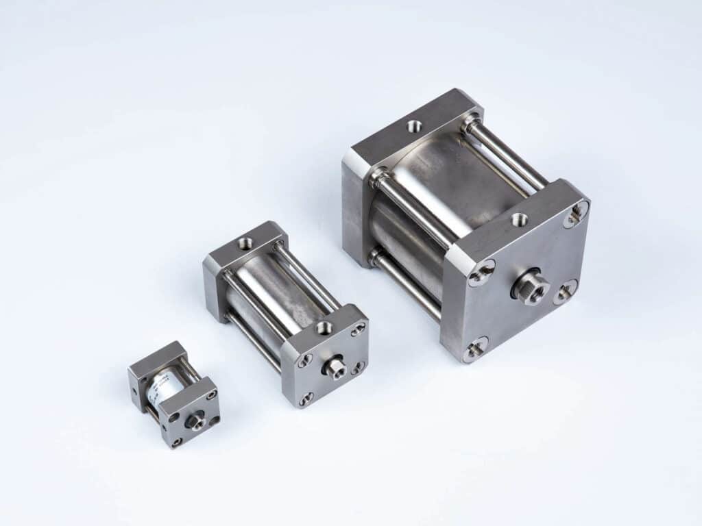
From our work, the most reliable sequence is source control, deflection, and then a model-approved scraper or bellows.
Match the rod protection to the material
A soft wiper may slide over particles fused to the rod. Festo’s metal wiper is intended for hard adhering particles, while Parker describes a metallic seal-wiper for high-temperature service with brick, ceramic, or cement dust (Parker EW seal-wiper, 2013). Check rod coating, speed, alignment, lubrication, and scraper compatibility.
Use bellows and shields without creating a new failure path
A bellows isolates the rod, seal, and bearing but changes package length and needs a breathing path. Festo says the DADB pressure-compensation opening must be ducted to avoid drawing in unwanted media. Shields also need full-stroke clearance, drainage, cooling, and inspection access.
Limit IP claims to the component actually rated
IEC explains that an IP code describes an enclosure’s protection against solids and water (IEC IP ratings, accessed July 17, 2026). An IP-rated switch does not certify the rod seal, scraper, guide, or whole axis. Likewise, purge air needs a manufacturer-defined inlet, outlet, flow or pressure limit, and clean-air requirement.
How Should Temperature and Material Limits Be Specified?
One SMC CA2 catalog lists a standard ambient range of -10°C to 70°C, a heat-resistant option to 110°C, and another option to 150°C; the 150°C version changes seals and grease and does not accept an auto switch (SMC CA2 catalog, accessed July 17, 2026). Temperature capability belongs to a complete model configuration.
Measure more than room temperature. A foundry specification should distinguish:
- maximum ambient temperature during production
- actuator body and piston-rod surface temperature
- compressed-air temperature at the inlet
- radiant exposure and distance from the hot source
- duration of each hot cycle and shutdown soak
- cold-start temperature after downtime
- temperature at the sensor, cable, fitting, lubricant, and nearby valve
The hottest point may occur after motion stops. A shield can reduce radiation during production yet slow cooling after shutdown. Log the temperature through the full machine state, not only while the axis moves.
Material names are also incomplete specifications:
| Material or feature | What it can address | What still needs verification |
|---|---|---|
| Stainless steel body or rod | Corrosion resistance for a defined exposure | Alloy, surface finish, galvanic contact, chloride or chemical compatibility |
| FKM-based seal | Some heat and chemical exposures | Exact compound, temperature-time profile, lubricant, pressure, motion, and media |
| PTFE-based element | Low friction or chemical resistance in a designed seal | Energizer, leakage, wear, groove, surface finish, and low-temperature behavior |
| Hard coating or chrome | Rod wear and surface durability | Coating thickness, adhesion, cracks, particle hardness, and scraper compatibility |
| Heat shield | Lower radiant load | Airflow, trapped heat, clearance, maintenance access, and splash direction |
Do not copy a 150°C label to another family. Confirm each model code, bore, stroke, mount, cushion, sensor, grease, and seal option.
Compressed-Air Quality at the Point of Use
ISO 8573-1 defines compressed-air purity through three principal classes for particles, water, and oil, and it allows those values to be specified or measured at different system locations (ISO, 2010). For a foundry actuator, the acceptance point should be near the protected machine, not assumed from a compressor-room filter label.
Point-of-use air quality is the measured particle, water, and oil condition at the location where the machine requires it. Write the required purity class from the actuator and valve documentation, then size separation, drains, drying, and filtration for actual inlet conditions and peak flow.
Do not treat filtration and external dust control as substitutes. A finer air filter cannot stop sand striking an exposed rod. A better scraper cannot remove liquid water or pipe scale carried inside the cylinder. The control-valve contamination guide explains how particles, water, oil, sampling point, and filter pressure drop affect the valve side of the same circuit.
Check the branch dynamically. Record pressure at the machine while the actuator and other high-demand equipment cycle. Inspect filter differential pressure and drain condition at the same time. If the point-of-use sample fails, work upstream through the branch instead of replacing another cylinder.
What Maintenance and Verification Prevent Catastrophic Failure?
OSHA’s minimal lockout procedure lists eight shutdown and isolation steps before equipment is considered locked out, including relief or restraint of stored air pressure and verification that the machine cannot operate (OSHA 1910.147 Appendix A, accessed July 17, 2026). Foundry actuator inspection must begin with the site’s validated energy-control procedure.
Condition-based maintenance is inspection and service triggered by measured condition, exposure, and trend rather than one universal calendar. A high-cycle scraper beside blasting equipment may need each-shift checks, while a shielded transfer cylinder can justify a different interval. Start conservatively, record evidence, and stay inside manufacturer requirements.
| Inspection item | Record | Escalation trigger |
|---|---|---|
| Rod and scraper | Deposit type, scratch direction, adhesion, exposed position | New scoring, packed debris, damaged edge, recurring deposit after cleaning |
| Bellows or guard | Tears, loose clamps, breathing path, trapped material | Hole, collapse, blocked vent, hot debris accumulation |
| Temperature | Ambient, body, rod, sensor, inlet air, machine state | Reading exceeds the exact component limit or trend rises from baseline |
| Air treatment | Drain operation, differential pressure, condensate, purity result | Water carryover, plugged element, failed class, corroded downstream pipe |
| Motion | Stroke time, end position, dynamic pressure, leakage, cushion behavior | Slower motion, impact, drift, incomplete stroke, pressure collapse |
| Mounting and load | Fastener marks, alignment, guide play, side load | Movement, uneven wear, binding, collision, load-path change |
Never blow foundry dust from a rod with uncontrolled compressed air. NIOSH recommends local exhaust, enclosure, wet methods where appropriate, and avoiding compressed-air housekeeping that redistributes silica dust (NIOSH silica work practices, 2024). Use a cleaning method approved for the process, contaminant, and electrical classification.
After repair, repeat the same loaded cycle and record the same fields used before repair. Acceptance should cover leakage, stroke time, end position, dynamic pressure, cushion behavior, scraper condition, sensor operation, and temperature at the worst approved production state. The broader pneumatic actuator maintenance checklist provides the isolation and recordkeeping framework.
What Should Go Into a Foundry Actuator RFQ?
Festo’s DSNU catalog separates heat-resistant seals to 120°C, rigid dust wipers for 32 to 63 mm bores, metal wipers for hard particles, corrosion protection, and bellows as different options (Festo, 2017). That separation shows why “foundry rated” is not a complete purchase specification.
Send suppliers the operating envelope, not only the old part number:
- actuator type, bore, stroke, load, speed, cycles, cushioning, mounting, and side-load conditions
- process zone and contaminant identity, including loose sand, bonded scale, grinding swarf, metal splash, water, oil, and cleaning chemicals
- maximum and minimum temperatures at the air, body, rod, sensor, valve, and cable, plus exposure duration
- required rod protection, scraper or wiper type, bellows, shield, guide protection, and allowed cleaning method
- compressed-air particle, water, and oil classes at the point of use
- sensor type, connector, cable, enclosure rating, hazardous-area classification, and required documentation
- inspection access, approved service parts, lubricant, replacement criteria, and acceptance test
Ask which claims apply to the complete actuator and which apply only to a seal, sensor, or accessory. Request the exact catalog page, drawing, test condition, and model-code suffix. The environmental actuator selection guide covers the wider heat, dust, washdown, corrosion, and hazardous-location review.
Our team found that replacement reviews are easier to verify when every limit is tied to one component, one machine state, and one acceptance test.
Define a fallback when the catalog product cannot meet the exposure. That may mean moving the actuator, adding a remote linkage, changing the guard, relocating the valve and sensors, or redesigning the process enclosure. Buying a more expensive cylinder without changing the exposure path often repeats the same failure.
Foundry Actuator FAQs: What Should Maintenance Teams Ask?
Model-specific limits are safer than industry folklore. SMC’s cited CA2 family spans a standard -10°C to 70°C range plus separate 110°C and 150°C options, while Festo treats dust wipers, metal wipers, and bellows as distinct configurations (SMC; Festo, accessed July 17, 2026).
How often should foundry actuator seals be replaced?
There is no defensible universal interval such as every two or four months. Set the interval from the exact manufacturer’s instructions, cycle count, temperature history, leakage trend, rod condition, and contaminant load. Festo lists different wiper and bellows configurations even within one 32 to 63 mm range, so exposure and hardware matter.
Can a standard pneumatic cylinder be retrofitted for foundry service?
Sometimes, but only with approved options and a verified operating envelope. Festo offers rigid and metal wipers plus bellows on specified DSNU sizes, while SMC lists a heavy-duty scraper option for its CA2 family. A field-made boot, guessed purge port, or incompatible seal kit does not create a validated foundry configuration.
Is stainless steel enough for a foundry actuator?
No. Stainless steel can address a defined corrosion exposure, but it does not establish heat resistance, abrasive-ingress protection, lubrication, sensor suitability, or scraper performance. SMC’s CA2 catalog separates corrosion-related material changes from its 110°C, 150°C, and heavy-duty-scraper options, showing that these requirements need separate model codes and checks.
Should foundry actuators use positive air purging?
Only when the actuator or protective enclosure has a manufacturer-defined purge design. Specify clean-air quality, inlet and outlet, pressure or flow limit, monitoring, and failure response. ISO 8573-1 requires particles, water, and oil to be specified at a defined location; feeding dirty plant air into a purge system can add contamination instead of preventing it.
What temperature rating does a foundry actuator need?
Use the highest measured temperature at every affected component through production and shutdown, then select a complete model above that envelope. In the cited SMC family, the standard limit is 70°C and separate options reach 110°C or 150°C. Those figures cannot be copied to another cylinder, sensor, grease, cable, or seal compound.
Sources and technical references
- NIOSH: Controlling Silica Dust from Foundry Casting-Cleaning Operations
- NIOSH: Silica Safe Work Practices
- ISO 8573-1:2010, Compressed-air contaminants and purity classes
- Festo DSNU/ESNU round-cylinder catalog
- Parker-Prädifa EW seal-wiper bulletin
- SMC CA2 cylinder catalog
- OSHA 29 CFR 1910.147, Control of hazardous energy