

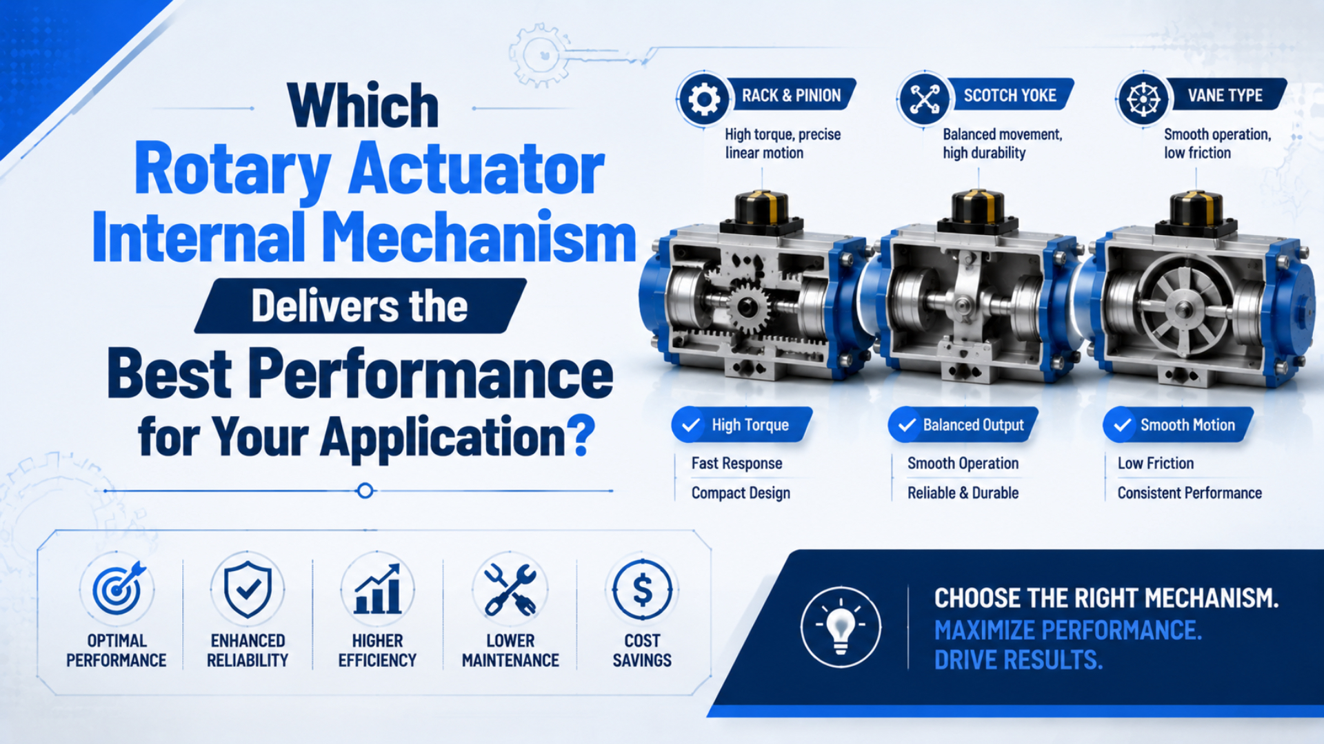
No rotary actuator internal mechanism delivers the best performance in every application. For general factory automation, rack-and-pinion is often the broadest starting point. A vane actuator can be the better package when a compact, limited-angle drive passes the torque, energy, and shaft-load checks. Scotch-yoke belongs mainly in part-turn valve automation, while current helical-spline products such as Parker Helac are hydraulic rather than direct substitutes for ordinary pneumatic rotary actuators.
The winning model is the one that supplies enough usable torque at the lowest pressure during motion, survives the load inertia and stopping energy, carries the external shaft loads, meets the required angle and repeatability, and provides the correct response when air or power is lost. A mechanism name alone proves none of those points.
Key Takeaways
- Define “best performance” as a measurable requirement before comparing mechanisms.
- Keep limited-angle pneumatic actuators, process-valve actuators, hydraulic helical-spline drives, and continuous-rotation air motors in separate candidate groups.
- Compare model-level torque, kinetic energy, shaft load, rotation time, backlash or repeatability, and stop design at the same operating conditions.
- Treat fail action, mounting interface, and environment as primary selection requirements.
- Use purchase price only after every candidate has passed the technical checks.

What Does “Best Performance” Mean for a Rotary Actuator?
Best performance means the actuator completes a defined motion with adequate margin and predictable behavior over the required duty. It does not mean the highest torque number, smallest body, or lowest price considered in isolation.
Start by converting the application into acceptance criteria:
- required rotation angle and adjustment range
- load torque, friction, gravity, inertia, and acceleration
- target move time, dwell time, cycles per minute, and annual cycles
- minimum pressure at the actuator while it moves
- allowed endpoint impact or stopping energy
- axial, radial, and moment loads on the output
- permitted backlash, end-position error, and repeatability
- mounting envelope, shaft or flange interface, and port access
- temperature, contamination, corrosion, washdown, or hazardous-area conditions
- double-acting or spring-return operation and the required loss-of-air state
These requirements can point in different directions. A compact actuator may need an external bearing that makes the installed assembly larger. A high-torque actuator may accelerate the load so aggressively that its internal stop cannot absorb the energy. A mechanism with low internal play may still miss the required angle because the coupling, fixture, sensor, or machine frame deflects.
The useful question is therefore not “Which mechanism is best?” It is “Which mechanism leaves the fewest unresolved risks after every candidate is normalized to the same motion, pressure, load, and failure condition?”
Which Mechanisms Belong in the Same Comparison?
SMC’s product guide places vane and rack-and-pinion units in its pneumatic rotary-actuator category. Festo’s DFPD process-valve range, by contrast, offers rack-and-pinion and scotch-yoke designs. Parker describes Helac as a helical hydraulic rotary-actuator family. These are related motion technologies, but they do not enter the same shortlist automatically (SMC, accessed July 17, 2026; Festo DFPD, accessed July 17, 2026; Parker Helac, accessed July 17, 2026).
| Candidate group | Typical role | Why it enters the shortlist | Boundary that can exclude it |
|---|---|---|---|
| Pneumatic rack-and-pinion | Indexing, flipping, diverters, fixtures, rotary tables | Broad model, torque, angle, stop, and load-support choices | Gear clearance, envelope, air consumption, or impact limits |
| Pneumatic vane | Compact limited-angle machine motion | Direct torque generation and a short package around the shaft | Model-specific torque, seal behavior, angle, and external-load limits |
| Pneumatic scotch-yoke | Quarter-turn process valves | Torque profile and spring-return options can suit valve breakaway or seating demand | Not a general replacement for a small indexing actuator |
| Hydraulic helical-spline | High-load mobile or industrial rotation | High power density and integrated load-bearing capability in current Helac products | Requires a hydraulic system and different leakage, safety, and maintenance controls |
| Pneumatic motor | Continuous or multi-turn motion | Appropriate when rotation must continue rather than stop at two angles | Needs separate speed, braking, positioning, and gearbox analysis |
This first classification prevents a common specification error: comparing a limited-angle pneumatic actuator with a hydraulic bearing actuator or an air motor only because all three turn a shaft.
If the motion requires continuous rotation, review the difference between pneumatic motors and rotary actuators before sizing a limited-angle device. For a detailed two-way comparison of the most common machine-automation mechanisms, use the dedicated rack-and-pinion versus vane guide.
When Is Rack-and-Pinion the Best Starting Point?
A rack-and-pinion actuator is a strong starting candidate when the application needs a wide model range, substantial torque, adjustable stops, supported output options, or a familiar indexing architecture. Pressurized air moves one or more pistons and racks; the rack teeth rotate a pinion connected to the output shaft.
A rack-and-pinion rotary actuator is a limited-angle drive that converts linear piston movement into output-shaft rotation through a rack and pinion.
Parker’s pneumatic range chart includes both vane and rack-and-pinion models, with rack-and-pinion models extending to the upper end of that catalog’s nominal torque range. Parker also cautions that the chart is only a guide and directs engineers to the actual product data because pressure, angle, options, and output vary by model (Parker pneumatic rotary actuator guide, accessed July 17, 2026).
That evidence supports a limited conclusion: rack-and-pinion offers broad high-output coverage in this product family. It does not prove that every rack actuator produces more torque, lasts longer, or positions more accurately than every vane actuator.
Rack-and-pinion deserves priority when:
- the shortlist needs several torque sizes or rotation options;
- the load requires an integrated rotary table or supported shaft;
- adjustable endpoints, cushions, shock absorbers, or external stops are important;
- a dual-rack layout provides the required output within the available envelope;
- process-valve duty requires a spring-return or double-acting rack actuator whose torque data match the valve curve.
Check the published backlash or repeatability rather than assuming gears make the unit inaccurate. Also verify what happens after wear, lubrication changes, or load reversal. End-position switches confirm a zone; they do not remove tooth clearance or external coupling play.
When Does a Vane Actuator Deliver the Better Package?
A vane actuator applies pressure to a sealed vane connected to the output rotor. It can produce direct limited-angle motion without a rack-and-pinion gear mesh, which can create a compact body around the shaft.
A vane rotary actuator is a limited-angle drive in which compressed air acts directly on one or more sealed vanes connected to the rotor.

Vane is a strong candidate when:
- radial or axial installation space is tightly constrained;
- the load and allowable endpoint energy fit a compact model;
- the required angle is available without a complex external linkage;
- the output is independently supported or the actuator’s own load ratings are adequate;
- direct limited-angle motion is more valuable than the breadth of a rack-and-pinion range.
Do not apply a universal “vane is smaller” or “vane is faster” rule. Installed size includes the support bearing, coupling, stop, sensor bracket, fittings, and service clearance. Speed depends on actuator volume, valve flow, tubing, exhaust restriction, load inertia, and deceleration settings. SMC treats rotation time, allowable kinetic energy, and allowable load as separate model-selection checks rather than consequences of the mechanism label (SMC rotary actuator selection guide, accessed July 17, 2026).
Single-vane and double-vane models also need separate rows in the comparison. Their torque, angle, volume, and package can differ even when the family name and outside dimensions look similar.
Where Does Scotch-Yoke Fit?
Scotch-yoke mechanisms are especially relevant to part-turn valve automation. The yoke converts piston travel into shaft rotation and produces a non-uniform torque curve. That characteristic can be useful when the required valve torque is highest near breakaway or seating, but the actual match depends on yoke geometry, spring arrangement, direction, and the valve’s measured torque curve.
A scotch-yoke actuator is a part-turn drive that converts piston motion through a slotted yoke, creating an angle-dependent torque profile.
Festo’s current DFPD documentation includes both rack-and-pinion and scotch-yoke versions in the same quarter-turn actuator family. It also distinguishes double-acting and single-acting configurations, showing why mechanism and fail action must be selected together (Festo DFPD, accessed July 17, 2026).
For a process valve, obtain at least:
- break-to-open torque
- running torque through travel
- end-to-close and unseat torque
- maximum differential pressure and process temperature
- normal direction and required fail position
- cycle frequency and modulating or on-off duty
- valve stem, mounting kit, and actuator flange details
ISO 5211:2026 specifies attachment dimensions, driving-component dimensions, and reference interface torque values for part-turn valve actuators. It does not size the actuator for a particular valve or process (ISO 5211:2026, 2026). A matching flange therefore proves mechanical interface compatibility, not adequate operating torque or safe failure behavior.
Why Isn’t Helical-Spline a Direct Pneumatic Alternative?
Parker’s current Helac line is explicitly a family of helical hydraulic rotary actuators. Hydraulic pressure moves a piston axially while two sets of helical splines rotate the piston and shaft. Parker positions these products for high load-bearing capacity, shock resistance, and mobile or heavy industrial duties (Parker Helac, accessed July 17, 2026).
A helical-spline rotary actuator converts axial piston travel into shaft rotation through meshing helical splines. The current Helac products discussed here use hydraulic power.
This mechanism may be appropriate when the machine already has hydraulic power and needs a compact actuator that also supports large external loads. It should not be presented as a Bepto pneumatic product or dropped into a compressed-air shortlist without accounting for:
- hydraulic power-unit availability
- fluid leakage and contamination consequences
- operating pressure and stored-energy hazards
- hose, valve, filtration, cooling, and service requirements
- hydraulic locking or load-holding behavior
- different purchasing and maintenance capabilities
Helical-spline is therefore a useful technology boundary, not a universal “precision upgrade” from a vane actuator. Precision still depends on the selected model, spline clearance, bearing deflection, external structure, feedback, control system, and load direction.
How Do You Compare Torque, Inertia, and Stopping Energy?
Required torque has several parts. For a machine indexing load, begin with:
where is the complete rotating assembly’s moment of inertia and is angular acceleration. Gravity torque must be included in when the center of mass rises or falls during rotation. For a valve, replace a generic load estimate with the valve supplier’s breakaway, running, and seating torque data.
Torque alone is not enough. Rotational kinetic energy before deceleration is:
where is angular speed. Because speed is squared, a faster move can exceed an internal stop’s energy limit even when static torque demand is small. Compare calculated energy with the exact actuator, cushion, shock absorber, or external-stop rating. Also confirm the permitted rotation-time range; slowing a pneumatic actuator excessively can cause unstable motion or stick-slip behavior in some configurations.
Use the calculator to organize the load estimate, then verify the result against the exact catalog at the minimum pressure measured while the actuator is moving.
For a complete sizing workflow, continue with the engineer’s guide to sizing pneumatic rotary actuators. The separate bore-size and rotary-torque guide explains why bore or frame size cannot be transferred between mechanisms.
Which Six Model-Level Checks Decide the Winner?
Mechanism tendencies help build a shortlist. These six checks select the model.
| Check | Data to compare on the same basis | Common reason a candidate fails |
|---|---|---|
| Usable torque | Operating or effective torque at minimum dynamic pressure and required angle | Headline torque is theoretical, quoted at higher pressure, or unavailable through the full motion |
| Inertia and stopping | Load inertia, target time, rotation speed, kinetic energy, cushion and stop rating | Torque passes but endpoint energy exceeds the permitted value |
| Output loading | Axial, radial, moment, belt, coupling, and fixture loads at actual offsets | Actuator can turn the load but cannot safely support it |
| Accuracy behavior | Backlash, repeatability, end-position error, reversal, stop stiffness, sensor hysteresis | “Precision” was never defined at the load |
| Motion and duty | Angle, adjustment, cycles per minute, annual cycles, dwell, temperature, air quality | Catalog test conditions do not represent the machine duty |
| Interface and failure | Shaft, key, flange, mounting, ports, fail position, manual override, feedback | The actuator fits the load but not the machine or safety function |
In our experience reviewing rotary-actuator applications, missing inertia and shaft-load data eliminate more confidence than a missing mechanism preference. A lightweight fixture with its mass far from the shaft can demand modest steady torque but create high acceleration torque, moment load, and endpoint energy. Sending the moving assembly drawing is often more valuable than requesting “the strongest 90-degree actuator.”
Which Mechanism Should You Start With by Application?
Use this matrix only to create the first shortlist. The validation column can reverse every initial choice.
| Application condition | Start with | Why | What can reverse the choice |
|---|---|---|---|
| General 90° or 180° indexing | Rack-and-pinion | Broad automation range and accessory choices | A vane model passes all checks in a smaller installed package |
| Compact light-load flip | Vane | Direct, limited-angle motion can minimize body size | External support, stops, or torque margin erase the package benefit |
| High-inertia indexing arm | Supported rack actuator or rotary table | Load-support and deceleration options are often available | Selected table still fails kinetic-energy or moment ratings |
| Quarter-turn process valve | Rack-and-pinion or scotch-yoke valve actuator | Fail action and torque curve can be matched to the valve | Valve torque data or package constraints favor the other mechanism |
| Several turns or continuous rotation | Pneumatic motor or another rotary drive | Limited-angle actuators may be the wrong category | A verified multi-turn rack design meets the exact travel and duty |
| Heavy load-bearing hydraulic machine | Helical-spline hydraulic actuator | Current products integrate rotation and load support | No hydraulic system, leakage risk, or control requirements exclude it |
| Tight end-position repeatability | Any candidate with published data and a rigid stop system | Result depends on the complete mechanism, stop, feedback, and structure | External play or load reversal dominates the actuator rating |
| Loss-of-air return required | Spring-return process actuator or engineered safe-state system | Failure response is designed into the package | Spring torque is insufficient across the full required travel |
Do not collapse “best cost-performance” into purchase price. Compare the installed package: actuator, valve, tubing, speed controls, stops, shock absorbers, support bearings, couplings, sensors, mounting kit, guarding, commissioning time, air or hydraulic energy, spares, and expected service work. The cheaper actuator is not cheaper if it needs a custom bearing structure or causes repeated stop damage.
How Should You Build the Final Candidate Worksheet?
Create one column for each exact model code, not each mechanism family. Normalize the entries before ranking them.
- Freeze the application case. Record angle, direction, move time, dwell, cycles, load geometry, inertia, pressure, environment, and fail state.
- Separate technology groups. Do not compare pneumatic, hydraulic, continuous-rotation, and part-turn valve products without accounting for their system requirements.
- Use one pressure basis. Compare pneumatic torque at the lowest expected inlet pressure during motion, including supply and exhaust losses.
- State the torque definition. Mark every value as theoretical, effective, operating, holding, or permissible.
- Check energy and loads independently. Do not let a torque safety factor stand in for kinetic-energy or bearing-load verification.
- Record missing data. An empty catalog cell becomes an RFQ question, not an assumed pass.
- Test the installed assembly. Confirm pressure at both ports, move time, endpoint behavior, repeatability, temperature, noise, and failure response under the worst credible production case.
For replacement work, include the full existing model code, mounting drawing, shaft dimensions, port locations, sensor part number, valve and tube sizes, pressure traces, cycle video, and observed failure. “Drop-in compatible” should mean verified dimensions, ratings, interfaces, and behavior, not only similar external appearance.
What Belongs on a Rotary Actuator RFQ?
Send the supplier enough information to reproduce the selection:
- application description and moving-assembly drawing
- required angle, adjustment window, direction, and number of turns
- move time, dwell time, cycles per minute, annual cycles, and expected life target
- load torque, gravity torque, friction, inertia, acceleration, and calculation method
- minimum pressure at the actuator while moving, maximum pressure, valve flow, tube length, and exhaust arrangement
- axial, radial, and moment loads with distances from the output shaft
- internal cushion, external stop, or shock-absorber requirement
- shaft, key, flange, coupling, mounting, port, and sensor interfaces
- temperature, dust, moisture, chemicals, corrosion, washdown, and hazardous-area requirements
- double-acting or spring-return operation, normal position, fail position, and manual override
- required backlash, repeatability, end-position error, and feedback method
Ask the supplier to identify the exact torque basis, rotation-time limits, allowable kinetic energy, permitted shaft loads, air consumption, environmental ratings, service instructions, and test conditions. If the application is a process valve, add the valve torque curve and ISO 5211 interface details. If it is a proposed cross-brand replacement, require a line-by-line dimensional and performance comparison rather than a general compatibility statement.
Jack Chen’s credentials are carried by the page author system. Bepto Pneumatic’s engineering and manufacturing scope is described on About Us, and readers can submit model data or request corrections through Contact.
Conclusion: The Best Mechanism Is the One That Passes the Whole Load Case
Rack-and-pinion is usually the broadest first candidate for factory indexing, while vane can win when its compact package passes every load and energy check. Scotch-yoke should be evaluated against a process valve’s torque curve and fail action. Current helical-spline products such as Parker Helac belong to the hydraulic boundary, and continuous rotation may require a pneumatic motor rather than a limited-angle actuator.
Select the technology group first, then compare exact models at the same pressure, angle, motion profile, and failure condition. Verify usable torque, inertia, stopping energy, shaft loads, repeatability, duty, interfaces, and installed cost separately. That process replaces a vague mechanism preference with a selection that engineering, purchasing, and maintenance can all audit.
If you send us the load drawing, angle, move time, dynamic pressure, mounting interface, and fail-state requirement, we can help organize the candidate worksheet and identify the model-level data still needed. Use the contact page to request an application review.
FAQs About Rotary Actuator Internal Mechanisms
The following answers preserve the same boundary used throughout this guide: mechanism names create a shortlist, while model-specific data decide suitability.
Is rack-and-pinion always better for high-cycle applications?
No. Cycle capability depends on the exact model, pressure, load, speed, lubrication policy, air quality, temperature, shaft loading, and endpoint impact. Rack-and-pinion offers a broad industrial range, but a vane model can be the better choice when its documented ratings cover the complete duty. Request life-test conditions for the selected configuration.
Is a vane actuator always more compact?
Not after installation. A vane body can be compact around the output shaft, but the complete assembly may also need a support bearing, coupling, external stop, sensor bracket, fittings, and service clearance. Compare the installed CAD envelope only after torque, energy, and shaft-load checks pass.
Can a helical-spline actuator replace a pneumatic rotary actuator?
Only after a system-level technology review. Current Parker Helac helical-spline actuators are hydraulic products, so they require hydraulic pressure, valves, hoses, filtration, leakage controls, and different safety and maintenance practices. They are not direct pneumatic replacements merely because both products rotate a shaft.
Should I choose the mechanism with the highest catalog torque?
No. First calculate load, friction, gravity, and acceleration torque at the real motion profile. Then compare usable torque at the minimum dynamic pressure. A candidate must also pass kinetic-energy, rotation-time, shaft-load, stop, repeatability, duty, and interface checks. Excess torque does not compensate for a failed energy or bearing limit.
Can ISO 5211 compatibility confirm correct valve-actuator sizing?
No. ISO 5211 defines part-turn actuator attachment interfaces and reference interface torque values. It does not prove that an actuator supplies the valve’s breakaway, running, seating, and unseating torque under actual process conditions. Validate the valve torque curve, mounting kit, fail action, environment, and complete assembled package.
Source Notes and Retrieval Dates
- SMC Rotary Actuator Product Selection Guide, vane and rack-and-pinion pneumatic rotary-actuator categories. Retrieved July 17, 2026.
- SMC Rotary Actuator Selection Guide, model-level rotation time, kinetic energy, load, and selection checks. Retrieved July 17, 2026.
- Parker Pneumatic Rotary Actuator Torque Guide, vane and rack-and-pinion range chart and product-data caution. Retrieved July 17, 2026.
- Festo DFPD Quarter-Turn Actuator, rack-and-pinion and scotch-yoke process-valve configurations. Retrieved July 17, 2026.
- Parker Helac Hydraulic Rotary Actuators, helical hydraulic operating principle and application boundary. Retrieved July 17, 2026.
- Parker Helac Series L and T Catalog, current helical hydraulic product family. Retrieved July 17, 2026.
- ISO 5211:2026, part-turn valve actuator attachment scope. Retrieved July 17, 2026.