

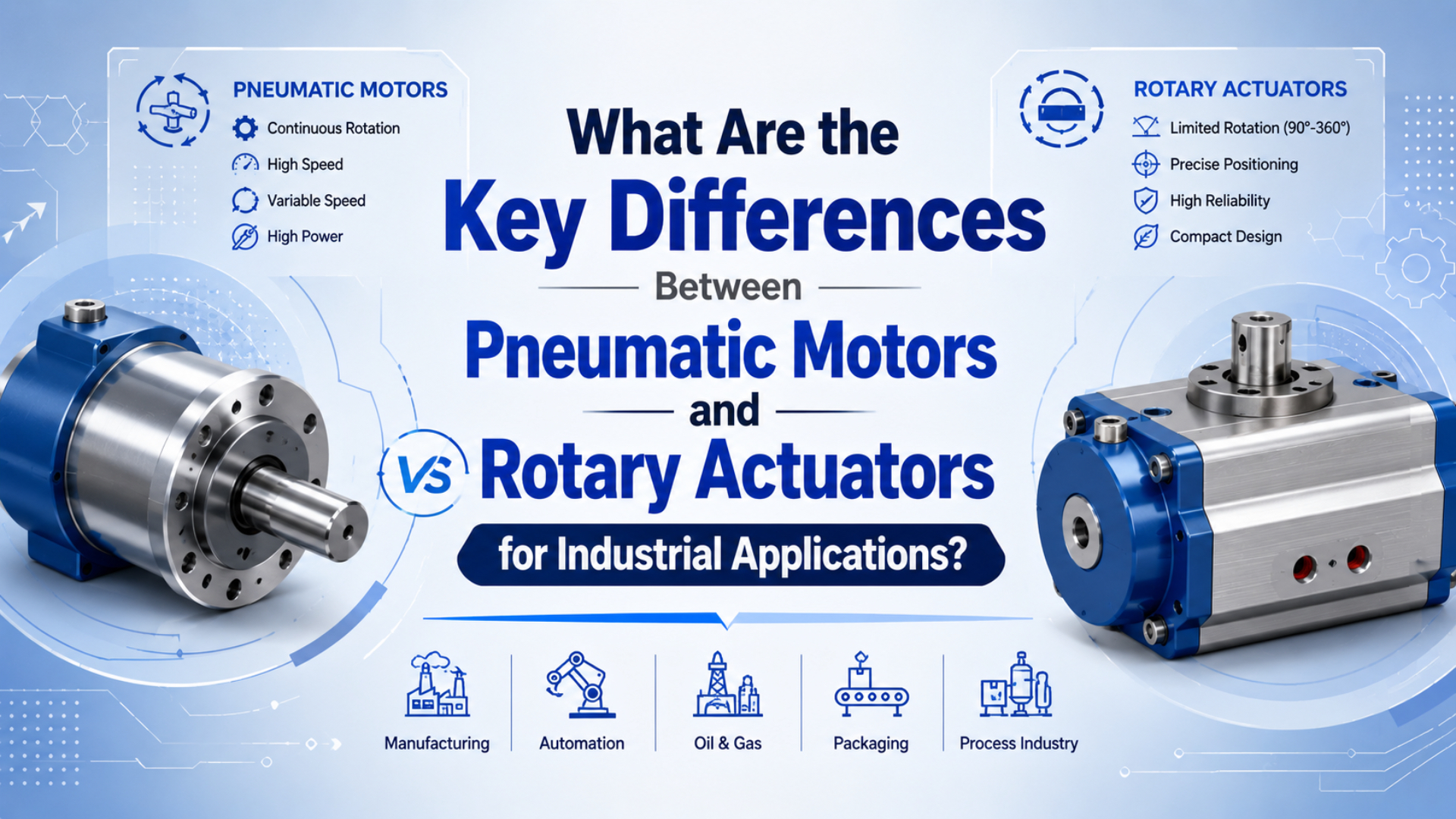
Pneumatic motors and rotary actuators both make air-powered rotation, but they solve different motion problems. A pneumatic motor is for continuous shaft rotation and speed control. A pneumatic rotary actuator is for a defined angular move, such as 90, 180, 190, or 270 deg in common SMC rotary actuator families (SMC USA Rotary Actuators, 2026).
The shortest selection rule is this: choose a pneumatic motor when the machine needs rpm; choose a rotary actuator when it needs angle. Mixing, grinding, stirring, fan drive, and conveyor assist usually point toward an air motor. Valve turning, gate motion, part flipping, and indexing usually point toward a rotary actuator.
Key Takeaways
- Pneumatic motors are continuous-rotation devices; Gast lists air motor speed classes from up to 2000 rpm through 10000+ rpm.
- Rotary actuators are limited-angle devices; SMC lists common arcs such as 90, 180, 190, or 270 deg.
- The best choice depends on motion profile first, then torque, stopping energy, position feedback, pressure, and air consumption.
The usual mistake is comparing torque numbers before defining the motion. A motor and a rotary actuator can both turn a shaft, but one is meant to keep turning and the other is meant to arrive at an angle, stop, confirm position, and repeat.
What Is the Main Difference Between Pneumatic Motors and Rotary Actuators?
The main difference is motion intent. Gast lists air motor catalog filters that include speeds up to 2000 rpm, 2000-5000 rpm, 5000-10000 rpm, and 10000+ rpm, while SMC lists rotary actuator arc options such as 90, 180, 190, and 270 deg (Gast Air Motors, 2026; SMC USA Rotary Actuators, 2026).
A pneumatic motor is an air-powered motor that turns continuously as long as compressed air is supplied and the load allows rotation. It is normally selected by speed range, torque curve, air consumption, duty, shaft style, mounting, and environment.
A pneumatic rotary actuator is an air-powered actuator that turns a shaft, table, lever, or valve stem through a limited angle. It is normally selected by angle, output torque, load inertia, stopping energy, end-position accuracy, sensor feedback, and mounting interface.
That makes the first interview question simple: does the shaft need to keep rotating, or does it need to move from one angular position to another? If the answer is “keep rotating,” start with an air motor. If the answer is “move to this angle and stop,” start with a rotary actuator.
| Selection question | Pneumatic motor | Rotary actuator |
|---|---|---|
| Motion output | Continuous shaft rotation | Limited angular movement |
| Typical command | run, stop, reverse, adjust speed | extend, retract, turn to end stop |
| Main variable | rpm and running torque | angle and output torque |
| Control focus | speed and load behavior | position, stop energy, feedback |
| Better fit | mixing, grinding, stirring, conveyor assist | valve turning, indexing, flipping, gate motion |
For broader actuator-family language, use the separate guide on what pneumatic actuators are and how they work. This article stays narrower: it compares a rotating motor with a limited-angle actuator.
How Do Pneumatic Motors Work in Continuous Rotation?
Pneumatic motors convert compressed-air flow into shaft rotation through vane, gear, turbine, or piston mechanisms. DEPRAG describes air motors as available in vane motors, gear motors, and turbines, with simple construction, a broad range of speeds, low power-to-weight ratio, and explosion-proof design (DEPRAG Air Motors, 2026).
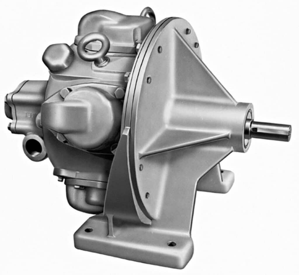
In a vane air motor, compressed air pushes vanes in a slotted rotor. The rotor turns the shaft. Speed changes with inlet pressure, flow control, exhaust restriction, load torque, and motor design. That is why an air motor is usually controlled like a rotating drive, not like a two-position cylinder.
Air motors are useful when the process wants motion more than position. A mixer does not need to stop at exactly 90 deg. A grinder does not care about home and work positions. A conveyor assist drive may need adjustable speed and reversing, but it usually does not need a hard angular stop.
In our experience, the risky air-motor RFQ is one that says only “need pneumatic rotary motion.” That phrase hides the real duty. The supplier still needs target rpm, continuous or intermittent duty, torque at running speed, starting load, air pressure, air flow, shaft direction, and whether the load can stall.
How Do Rotary Actuators Work in Limited-Angle Motion?
Rotary actuators turn compressed air into a controlled angular move, not open-ended rotation. AutomationDirect describes pneumatic rotary actuators as devices for flip, tilt, or turn actions and notes that they typically do not rotate more than 270 deg (AutomationDirect Library, 2016).
For factory automation, the common families are rack-and-pinion and vane rotary actuators. A rack-and-pinion actuator starts with piston force, moves a rack, and turns a pinion. A vane actuator pushes a vane attached to the output shaft through a chamber. Process valve actuators may use rack-and-pinion, scotch-yoke, or other torque mechanisms.
The strength of a rotary actuator is repeatable angle. It can turn a diverter gate to a stop, flip a part into a nest, rotate a gripper wrist, or operate a quarter-turn valve. It can also carry end-position switches so the machine controller knows whether the move is complete.
For the detailed mechanism, do not duplicate this page. Use the dedicated guide on how pneumatic rotary actuators work. This comparison article should answer whether the buyer should be looking at an air motor or an actuator in the first place.
How Should Speed, Torque, and Position Control Be Compared?
Compare the two devices by the variable the machine must control. Gast air motor filters include 10000+ rpm speed classes and torque bands above 118.63 Nm, while SMC rotary actuator pages focus on actuator families and angle ranges rather than continuous rpm (Gast Air Motors, 2026; SMC USA Rotary Actuators, 2026).
For a motor, torque is not enough. You need torque at the intended speed. A motor can have high starting torque and still be wrong if it consumes too much air at the required rpm, overspeeds under light load, or slows too much when the process thickens.
For a rotary actuator, peak torque is not enough either. You need torque at the available moving pressure, plus enough margin for breakaway, friction, acceleration, and stop energy. Parker’s rotary actuator sizing guidance defines demand torque as load torque plus friction torque plus acceleration torque, with the designer adding a design factor (Parker Rotary Actuator Torque Requirements, 2026).
Use the comparison this way:
| Requirement | Pneumatic motor check | Rotary actuator check |
|---|---|---|
| Speed | rpm under load, air flow, governor or valve control | swing time, cushion time, end-stop impact |
| Torque | starting torque and running torque at rpm | load torque, friction torque, acceleration torque |
| Position | poor fit without added feedback and brake | natural fit for end positions and limited angle |
| Stall behavior | can stall and restart, but heat, wear, and air use matter | may stall before reaching end position if undersized |
| Feedback | encoder or speed sensor if required | reed switch, proximity switch, encoder, or positioner |
| Failure mode | low speed, stall, air waste, bearing wear | overshoot, bounce, stop damage, missed sensor |
This is why a pneumatic motor should not be used as a cheap positioning actuator without a brake, feedback, and control strategy. It is also why a rotary actuator should not be used as a mixer. It can turn, but it is not built to spin continuously.
Which Applications Fit Each Device Best?
Applications split cleanly once the motion profile is clear. AutomationDirect places pneumatic rotary actuators in flip, tilt, and turn applications with typical limited rotation, while Gast presents air motors for industrial compressed-air motor and pneumatic gear motor applications across speed and torque classes (AutomationDirect Library, 2016; Gast Air Motors, 2026).
Choose pneumatic motors when the process needs rotation as an ongoing action:
- Mixing, blending, and agitation.
- Grinding, polishing, sanding, or brushing.
- Small conveyor or roller assist.
- Pump, fan, or spindle-like drive.
- Hazardous or wet environments where air power is preferred over electric drive.
Choose rotary actuators when the process needs angular position:
- Quarter-turn valve operation.
- Product diverter gates.
- Indexing stops and part orientation.
- Pick-and-place gripper rotation.
- Fixture flip, tilt, and clamp mechanisms.
From application reviews, the fastest way to expose the wrong choice is to ask what happens at the end of motion. If the answer is “nothing, it keeps spinning,” the job is motor-like. If the answer is “it must stop, confirm, and wait for the next station,” the job is actuator-like.
What Selection Mistakes Cause Performance Problems?
Most failures come from treating rotary devices as interchangeable. CAGI says a well-designed compressed-air system should keep pressure drop from compressor discharge to point of use within 10 percent; that matters because both motor speed and actuator torque depend on pressure and flow at the device, not only compressor-room pressure (CAGI Pressure Drop Technical Brief, 2026).
DOE’s compressed-air systems page groups assessment tools, training, tip sheets, case studies, and technical publications for system-level compressed-air work, which is the right source family when air consumption or pressure drop becomes a plant-wide issue (DOE Compressed Air Systems, 2026).
The common wrong selections are predictable:
| Mistake | Why it fails | Better action |
|---|---|---|
| Using an air motor for valve positioning | It spins; it does not naturally stop at a precise angle | Use a rotary actuator with stops and feedback |
| Using a rotary actuator for continuous mixing | Limited-angle seals and stops are not meant for continuous rpm | Use a pneumatic motor sized for duty and rpm |
| Comparing only peak torque | Peak torque does not prove speed, energy, or pressure margin | Compare torque at actual pressure and motion state |
| Ignoring air consumption | A motor can use air continuously; an actuator uses pulses | Include flow and duty in operating-cost review |
| Ignoring stopping energy | A rotary actuator can have enough torque but still damage stops | Check inertia, cushion, bumper, or shock absorber |
| Trusting catalog pressure | Point-of-use pressure can drop during motion | Measure pressure while the device is running |
The choice also affects controls. A motor circuit may need a flow control, reversing valve, muffler, speed sensor, or pressure regulator. A rotary actuator circuit may need meter-out speed control, end-position sensors, cushions, shock absorbers, and a valve sized for the required swing time.
What RFQ Data Should You Send Before Choosing?
Send different data for a motor and an actuator. Parker’s rotary sizing guidance uses load, friction, and acceleration torque for actuator demand torque, while Gast’s air motor catalog filters by speed and max torque, so the supplier needs the right variables for the right device (Parker Rotary Actuator Torque Requirements, 2026; Gast Air Motors, 2026).
For a pneumatic motor RFQ, include:
- Target rpm range and whether speed must stay constant under load.
- Starting torque, running torque, and stall condition.
- Duty cycle: continuous, intermittent, reversing, or frequent start-stop.
- Available pressure and flow at the motor inlet.
- Shaft style, mounting pattern, load coupling, and expected side load.
- Environment: washdown, dust, oil mist, temperature, corrosion, or hazardous area.
For a rotary actuator RFQ, include:
- Required angle, adjustable stop range, and return direction.
- Load torque, lever arm, inertia, friction, and orientation.
- Swing time, cycle rate, dwell time, and stop method.
- Available pressure during motion, valve size, tube ID, and tube length.
- Feedback needs: reed switch, proximity switch, encoder, or no feedback.
- Mounting interface, shaft load support, valve interface, and safety state.
If the system is already built, send a short video of the motion, photos of the valve station, and measured pressure during the motion. That evidence prevents the supplier from sizing a motor or actuator against clean catalog conditions that do not exist in the machine. For application review, you can also contact Bepto Pneumatic with the motion profile and the pressure data.
For adjacent checks, use the guides on pneumatic rotary actuator operation, compressed-air flow and pressure, and pneumatic energy efficiency.
FAQs About Pneumatic Motors and Rotary Actuators
Is a pneumatic motor the same as a rotary actuator?
No. A pneumatic motor is designed for continuous shaft rotation, usually selected by rpm, torque at speed, air consumption, and duty. A pneumatic rotary actuator is designed for limited-angle movement, usually selected by angle, torque, stop energy, feedback, and available moving pressure.
When should I choose a pneumatic motor?
Choose a pneumatic motor when the process needs ongoing rotation, such as mixing, stirring, grinding, polishing, brushing, fan drive, or conveyor assist. Gast lists air motor speed categories up to 10000+ rpm, which points to motor-style continuous rotation rather than end-position control.
When should I choose a rotary actuator?
Choose a rotary actuator when the machine needs a controlled angular move: flip, turn, index, open, close, or swing to a stop. SMC lists rotary actuator arcs such as 90, 180, 190, and 270 deg, which fits limited-angle positioning rather than continuous rpm.
Can a pneumatic motor be used for positioning?
Only with extra control hardware. A pneumatic motor can be paired with feedback, braking, and control logic, but it is not naturally a precise positioning device. If the motion has two end positions, a rotary actuator with stops and sensors is usually the cleaner starting point.
Can a rotary actuator run continuously like a motor?
No, not as a normal design assumption. A rotary actuator is built for limited-angle cycles and end-position control. Using it as a continuous drive can damage seals, stops, cushions, or bearings. Use an air motor when the shaft must keep rotating.
Which one uses more compressed air?
It depends on duty, load, pressure, and flow control. A pneumatic motor can use air continuously while it rotates. A rotary actuator usually consumes air in movement pulses. CAGI’s 10 percent pressure-drop target is a useful reminder to measure point-of-use pressure and flow instead of trusting compressor-room values.
External Technical References
These fact-check references support the technical framing in this article. They do not replace the motor, actuator, valve, or air-preparation supplier’s own flow curves, torque tables, duty ratings, and operating limits.
- SMC USA Rotary Actuators: Supports rotary actuator family framing and common limited-angle actuator arcs such as 90, 180, 190, and 270 deg. Retrieved 2026-07-08.
- Gast Air Motors: Supports air motor category framing, speed classes up to 10000+ rpm, and torque filter ranges for industrial air motors. Retrieved 2026-07-08.
- DEPRAG Air Motors: Supports air motor design families, broad speed range language, simple construction, low power-to-weight ratio, and explosion-proof design context. Retrieved 2026-07-08.
- AutomationDirect Pneumatic Actuator vs Electromechanical: Supports rotary actuator use cases for flip, tilt, and turn actions and typical limited rotation. Retrieved 2026-07-08.
- Parker Rotary Actuator Torque Requirements: Supports demand torque framing using load torque, friction torque, and acceleration torque. Retrieved 2026-07-08.
- CAGI Pressure Drop Technical Brief: Supports point-of-use pressure-drop guidance and the 10 percent system pressure-drop target. Retrieved 2026-07-08.
- DOE Compressed Air Systems: Supports system-level compressed-air assessment context, including tools, training, tip sheets, case studies, and technical publications. Retrieved 2026-07-08.