

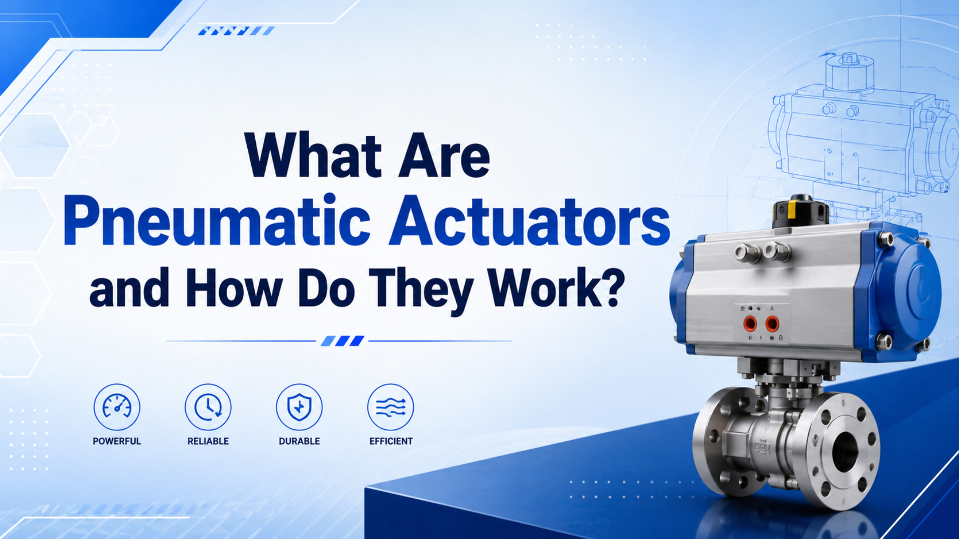
Pneumatic actuators are compressed-air devices that create machine motion. They can push, pull, lift, clamp, grip, rotate, index, stop, or shift a part. Festo defines actuators as devices that convert electrical, pneumatic, or hydraulic power into mechanical motion, and says pneumatic drives commonly handle clamping, lifting, lowering, gripping, and stopping tasks (Festo, 2026).
The short version is simple: compressed air enters a chamber, pressure acts on an area, and that force moves a piston, vane, rack, diaphragm, jaw, or carriage. The hard part is choosing the right actuator family before you size the part.
Key Takeaways
- Pneumatic actuators include linear cylinders, rodless axes, guided slides, rotary actuators, grippers, clamps, and specialty units.
- ISO 15552 covers detachable-mounting pneumatic cylinders up to 1,000 kPa, or 10 bar, with 32-320 mm bores.
- CAGI says well-designed compressed-air systems usually stay within 10% pressure drop from compressor discharge to point of use.
The useful buyer question is not “What is a pneumatic actuator?” It is “Which air-powered motion job do I actually have?” A clamp, a diverter, a lift, a pick-and-place gripper, and a rotary indexer all use compressed air, but they fail for different reasons.
What Is a Pneumatic Actuator?
A pneumatic actuator is an air-powered device that converts compressed-air energy into mechanical motion. Festo says a pneumatic cylinder is an actuator operated with compressed air, usually up to a maximum of 12 bar, and it can generate linear or rotary motion (Festo, 2026).
That definition matters because “pneumatic actuator” is a family name, not one part number. A standard cylinder, compact cylinder, rodless cylinder, guided slide, rotary actuator, pneumatic gripper, stopper cylinder, clamp, and process-valve actuator can all sit under the same umbrella.
If a purchasing note only says “air actuator,” the supplier has to guess. Does the machine need a straight stroke, a guided load, an angular move, a gripping jaw, or a valve stem movement? The answer changes bore, stroke, seals, valves, sensors, tubing, and safety state.
Use this quick hierarchy:
Pneumatic actuator
  -> linear actuator: cylinder, guided slide, rodless cylinder
  -> rotary actuator: rack-and-pinion, vane, scotch-yoke process valve actuator
  -> gripping actuator: parallel gripper, angular gripper, toggle clamp
  -> specialty actuator: stopper, swing clamp, multi-position unit, bellows unit
For cylinder terminology, keep the distinction clean. A pneumatic cylinder is a common pneumatic actuator type. It is not the whole category.
How Do Pneumatic Actuators Turn Air Pressure Into Motion?
Pneumatic actuators work when compressed air creates pressure over an effective area. NASA states that force equals pressure times area, and CAGI says most well-designed compressed-air systems stay within 10% pressure drop to the point of use (NASA Glenn, 2023; CAGI, 2026).
For a linear cylinder, air enters one chamber and pushes a piston. The piston moves a rod or carriage. The opposite chamber exhausts through the valve. Reverse the valve, and the motion reverses. That is the same working path explained in the detailed guide on how a pneumatic cylinder works in automation.
For a rotary actuator, the pressure acts on a rack-driven piston, vane, or scotch-yoke mechanism. The actuator turns a shaft or table through a limited angle. For a gripper, pressure moves a piston or wedge that closes jaws around a part.
The first force estimate for a linear actuator is:
Force = working pressure x effective areaFor extension, effective area is usually the full piston area. For retraction on a single-rod cylinder, subtract rod area. That is why pull force is usually lower than push force on the same bore.
From application reviews, the most common sizing error is trusting compressor-room pressure. A 6 bar header does not guarantee 6 bar at the actuator during motion. Valve Cv, tubing length, filter condition, regulator droop, and exhaust restriction decide what pressure the piston actually sees.
Pneumatic Actuator Types: Linear, Rotary, Gripping, and Specialty Units
The main pneumatic actuator families are linear, guided, gripper, rotary, rodless, clamp, and specialty units. SMC groups pneumatic actuators into linear actuators, guided actuators, grippers, rotary actuators, rodless actuators, clamps, and specialty actuators, while its rotary page lists rack-and-pinion and vane types (SMC USA, 2026).
| Actuator family | Motion output | Typical machine job | Main sizing input |
|---|---|---|---|
| Standard cylinder | Straight-line rod motion | push, pull, lift, stop, eject | force, bore, stroke, mounting |
| Rodless cylinder | Straight-line carriage motion | long transfer in short footprint | stroke, load moment, guide load |
| Guided slide | Guided straight-line motion | part presentation, tooling slide | load, moment, anti-rotation need |
| Rotary actuator | Limited-angle shaft or table motion | turn, flip, index, valve operation | torque, angle, inertia, end stop |
| Pneumatic gripper | Jaw closing or opening | pick-and-place, holding, transfer | grip force, part mass, friction |
| Clamp or stopper | Hold or stop motion | fixture, conveyor stop, nest lock | holding force, release state |
Do not treat those as interchangeable choices. A standard cylinder is not a guide. A rodless cylinder is not a servo axis by default. A gripper is not only a small clamp. A rotary actuator is not an air motor. Each family has a different load path and failure mode.
For deeper branch pages, use the related articles on rodless actuators, pneumatic rotary actuators, and single-acting vs double-acting cylinders.
How Do Linear, Rotary, and Gripping Actuators Differ?
Linear, rotary, and gripping actuators differ by output motion and load path. ISO 15552 covers 10 bar pneumatic cylinders with 32-320 mm bores, while SMC lists rotary actuator arc lengths of 90, 180, 190, or 270 deg (ISO, 2025; SMC USA, 2026).
A linear cylinder is the default choice for simple straight motion. It pushes a rod or carriage. The load should be guided by the machine or by a guided cylinder. If the cylinder rod is asked to carry side load, it can bind, wear seals, bend, or lose repeatability.
A rotary actuator solves a different problem. It turns a shaft, table, lever, gate, or valve stem. SMC separates rack-and-pinion and vane styles. AutomationDirect notes that pneumatic rotary actuators can flip, tilt, or turn a part and typically do not rotate more than 270 degrees (AutomationDirect, 2016).
A gripper turns pneumatic force into jaw force. Parallel grippers close in a straight path. Angular grippers pivot. Toggle and cam designs change force over the stroke. For grippers, part geometry and friction matter as much as supply pressure.
| Selection question | Linear cylinder | Rotary actuator | Pneumatic gripper |
|---|---|---|---|
| What moves? | rod, carriage, slide | shaft, table, lever | jaws or fingers |
| Main output | force over stroke | torque over angle | holding force |
| Common mistake | using rod as a guide | ignoring inertia and end stops | ignoring friction and acceleration |
| Best companion check | bore, rod, stroke, flow | torque, angle, stop energy | jaw force and part security |
This is where the page should stay a hub. If the reader already knows the family, send them to the detailed page. If they do not know the family, keep them here long enough to choose the right branch.
How Should You Size a Pneumatic Actuator?
Size a pneumatic actuator from the load case, not the catalog name. For air delivery, CAGI recommends no more than 10% pressure drop to the point of use, so sizing should use measured moving pressure at the actuator (CAGI, 2026).
For linear motion, start with the force requirement. Include load weight, friction, acceleration, vertical direction, tooling mass, and safety factor. Then compare available force at the lowest expected moving pressure, not only at nominal plant pressure.
For rotary motion, start with torque. Include breakaway torque, load torque, friction torque, acceleration torque, and stop energy. A rotary actuator that turns an empty table may fail when a loaded part arrives because inertia changes the stopping event.
For gripping, start with the part. Record mass, center of gravity, surface material, friction coefficient, acceleration, orientation, jaw length, jaw contact area, and release condition. A gripper that holds a dry machined part may drop an oily part of the same mass.
Use this minimum sizing sequence:
- Define motion: stroke, angle, jaw travel, or clamp path.
- Define load: mass, friction, force, torque, center of gravity, and acceleration.
- Define pressure: lowest moving pressure at the actuator, not only compressor pressure.
- Define flow: required cycle time and exhaust path.
- Define control: valve type, sensors, mid-position need, and safety state.
- Define environment: dust, washdown, heat, oil mist, chemicals, or cleanroom limits.
For force-heavy linear applications, the companion cylinder force calculator and cylinder flow requirement calculator can turn those inputs into a better first quote.
What Air Supply and Control Checks Matter?
Air supply and controls decide whether the selected actuator performs in the machine. CAGI says well-designed compressed-air systems usually stay within 10% pressure drop and recommends piping air velocity of 20 ft/s or lower to reduce turbulence and pressure drop (CAGI, 2026).
Check these before approving the actuator:
| System check | Why it matters | What to document |
|---|---|---|
| Point-of-use pressure | force and torque depend on actual pressure | measured pressure during motion |
| Valve flow | small valves slow cylinders and starve rotary actuators | valve Cv or flow rating |
| Tubing length and ID | long or small tube adds pressure drop and delay | tube ID, length, fittings |
| Exhaust path | blocked silencers and speed controls slow return strokes | muffler, flow control, exhaust route |
| Air quality | water and particles shorten seal life | filtration, dryness, oil policy |
| Sensors | PLC needs proof of motion and safe state | reed switch, proximity, pressure, encoder |
The valve decision is not separate from the actuator. A basic two-position cylinder can use a standard solenoid valve. A speed-sensitive actuator may need better flow control. A mid-position or force-controlled actuator may need proportional valves, feedback, or servo-pneumatic hardware.
Air preparation belongs in the same review. Festo describes servo-pneumatic positioning as a system that includes a cylinder, displacement encoder, proportional directional control valve, and positioning controller. That is a system architecture, not just a cylinder upgrade (Festo, 2026).
If pressure stability is weak, read the dedicated article on pressure fluctuations in pneumatic systems before upsizing the actuator. A larger bore can hide an air supply problem for a while, then increase air consumption and cycle-time variation.
Where Do Pneumatic Actuators Fit Best?
Pneumatic actuators fit best where the motion is simple, fast, rugged, and supported by an existing air system. CAGI says compressed air requires about 8 horsepower of electrical energy to produce 1 horsepower of compressed-air energy, so air should be used where its production, safety, or integration benefits justify the utility cost (CAGI, 2026).
Good pneumatic actuator applications include:
| Application | Good pneumatic fit | Watch item |
|---|---|---|
| Conveyor stop | short stroke, high repeat count | impact load and sensor proof |
| Packaging reject | fast two-position push | valve flow and exhaust noise |
| Fixture clamp | simple hold and release | trapped pressure and part damage |
| Pick-and-place gripper | light, fast part handling | friction, part surface, acceleration |
| Rotary diverter | limited-angle turn | inertia, stop energy, angle feedback |
| Long transfer | rodless or guided linear motion | load moment and guide sizing |
Pneumatics is weaker when the job needs many programmable positions, smooth motion profiles, high stiffness, detailed force feedback, or high continuous duty with tight energy accounting. That does not make air a poor choice. It means the requirement should be honest.
For comparison decisions, use the related guide on when to choose a cylinder over an electric actuator and the mixed-system article on using cylinders and electric actuators together. Those pages keep this hub from turning into a cylinder-vs-electric debate.
The best pneumatic actuator jobs often look boring on paper: two stops, short moves, clear load path, known pressure, simple sensors, accessible fittings. Boring is a compliment in factory automation. It usually means the actuator is doing one job and the machine is not asking air compressibility to become servo stiffness.
RFQ Checklist for Pneumatic Actuator Selection
A pneumatic actuator RFQ should describe motion, load, pressure, flow, controls, and environment. Festo says pneumatic drives handle jobs such as clamping, lifting, lowering, gripping, and stopping, while CAGI says compressed-air equipment sizing starts from 3 parameters: demand, pressure, and air quality (Festo, 2026; CAGI, 2026).
Send this information with the quote request:
| RFQ field | What to include |
|---|---|
| Motion type | linear stroke, rotary angle, jaw travel, clamp action, or stopper action |
| Load | part mass, tooling mass, friction, center of gravity, and acceleration |
| Required output | push force, pull force, torque, grip force, or holding force |
| Pressure | available supply pressure and measured point-of-use pressure during motion |
| Speed | required stroke time, dwell time, cycle rate, and duty cycle |
| Mounting | orientation, bracket, guide, side load, moment load, and space limits |
| Control | valve type, voltage, sensors, feedback, manual override, and PLC state |
| Environment | temperature, dust, washdown, chemicals, oil, food contact, or cleanroom |
| Safety state | what happens after E-stop, pressure loss, or power loss |
| Maintenance | access to seals, fittings, silencers, sensors, and replacement parts |
Avoid sending only an old part number when the application changed. The old actuator may be correct for the old load and wrong for the new speed, orientation, guide, or control sequence.
For plant-air support, note whether an FRL unit already exists at the station. For long-stroke linear motion, note whether the target is a rodless cylinder or a guided slide. For unit confusion, add pressure and flow units clearly, or use the combined converter.
FAQs About Pneumatic Actuators
Pneumatic actuator FAQs should separate family definition from detailed sizing. ISO 15552 defines one standardized pneumatic cylinder group at 10 bar and 32-320 mm bores, while SMC lists rotary actuators with 90, 180, 190, or 270 deg arcs (ISO, 2025; SMC USA, 2026).
What is the difference between a pneumatic actuator and a pneumatic cylinder?
A pneumatic actuator is the full air-powered motion category. A pneumatic cylinder is one linear actuator type inside that category. ISO 15552 covers detachable-mounting pneumatic cylinders in a 10 bar, 32-320 mm bore series, but rotary actuators, grippers, clamps, and rodless units are also pneumatic actuators.
Can pneumatic actuators stop at intermediate positions?
Yes, but a basic on-off valve and end sensors usually give only two positions. Festo describes servo-pneumatic positioning as a system with a cylinder, displacement encoder, proportional directional valve, and positioning controller. If the machine needs many stops, include feedback and control hardware in the quote.
How do I size a pneumatic actuator?
Start with force, torque, or grip force, then check stroke, angle, jaw travel, cycle time, pressure, and flow. NASA’s pressure-area relation supports Force = pressure x area, but CAGI’s 10% pressure-drop guidance means you should size from measured point-of-use pressure during motion.
Are pneumatic actuators cheaper than electric actuators?
Sometimes. Pneumatic devices can be simple and low cost at the component level, but CAGI says producing 1 horsepower of compressed-air energy takes about 8 horsepower of electrical energy. Compare installed cost, utility cost, maintenance, controls, and downtime, not only actuator purchase price.
Which pneumatic actuator is best for pick-and-place?
It depends on the motion. AutomationDirect says pneumatic pick-and-place systems use cylinders for linear or rotary movement, rotary actuators for flip or turn actions, and grippers or vacuum cups as end effectors. Start with stroke, payload, orientation, required speed, and part surface before choosing hardware.
Sources and Further Reading
The detailed sources below support actuator-family checks, force math, air-supply assumptions, and RFQ boundaries, including ISO 15552 for 10 bar cylinder scope and CAGI for pressure-drop guidance.
- ISO 15552:2018, pneumatic cylinders with detachable mountings, 1,000 kPa or 10 bar series, and 32-320 mm bores. Retrieved 2026-07-08.
- Festo: Actuators and Drives, actuator definition, pneumatic drive applications, 12 bar pneumatic-cylinder context, and servo-pneumatic positioning architecture. Retrieved 2026-07-08.
- SMC USA: Rotary Actuators, pneumatic actuator categories, rack-and-pinion and vane styles, and 90, 180, 190, and 270 deg rotary actuator arcs. Retrieved 2026-07-08.
- AutomationDirect: Pneumatic Actuator vs Electromechanical, pneumatic pick-and-place, cylinders, rotary actuators, grippers, stroke limits, and speed-control notes. Retrieved 2026-07-08.
- AutomationDirect video: What is a Pneumatic Cylinder?, visual background for linear pneumatic cylinders. Retrieved 2026-07-08.
- CAGI Pressure Drop Technical Brief, 10% pressure-drop target, 20 ft/s piping velocity recommendation, and filter differential pressure guidance. Retrieved 2026-07-08.
- CAGI: Working With Compressed Air, compressed air as the fourth utility, energy conversion context, demand-pressure-air-quality sizing, leaks, and operating cost. Retrieved 2026-07-08.
- NASA Glenn: Aerodynamic Forces, pressure times area force relation. Retrieved 2026-07-08.