

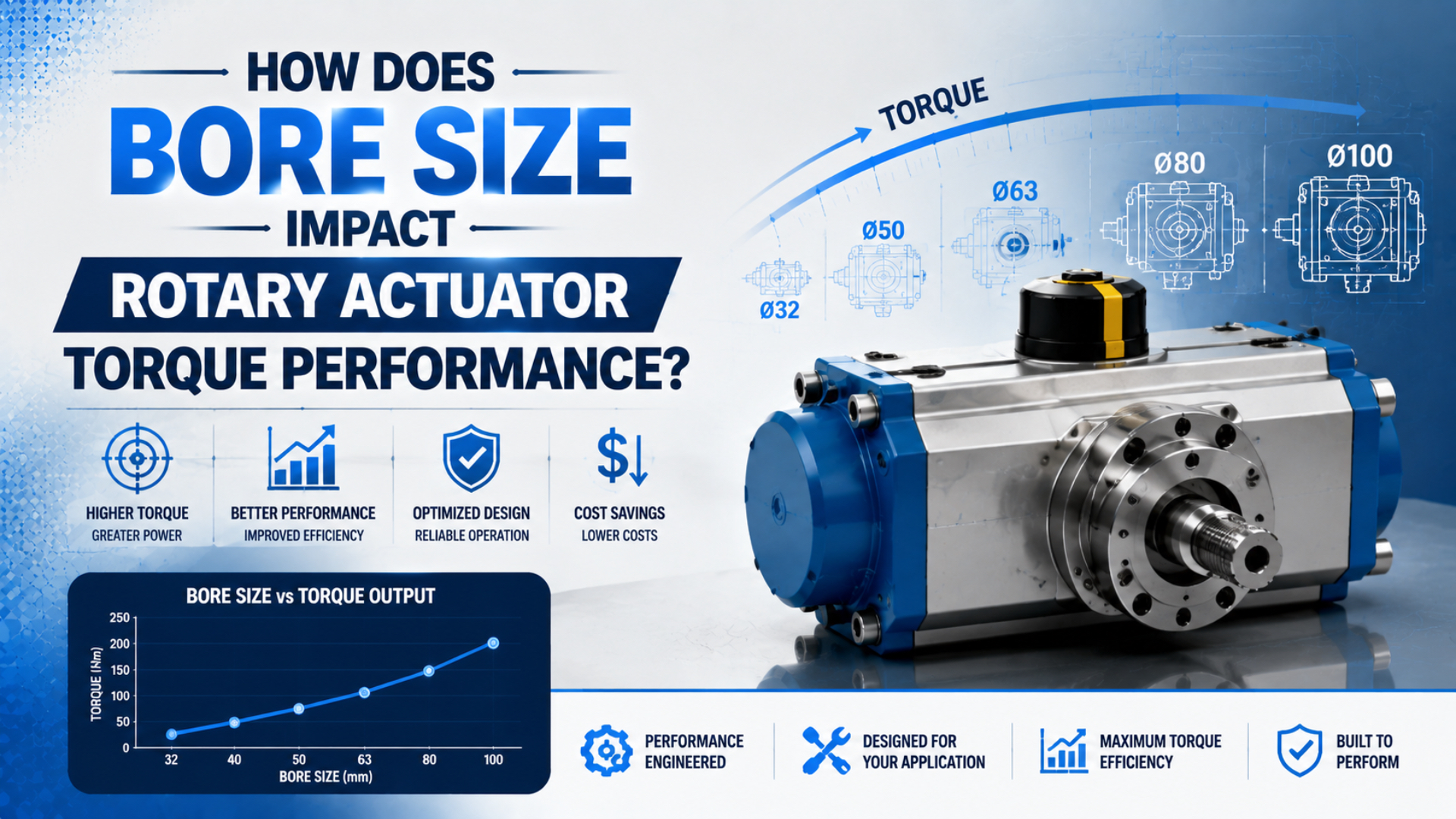
A larger bore usually raises a pneumatic rotary actuator’s torque because it creates more pressure area, but bore diameter alone does not determine output torque. In a rack-and-pinion unit, theoretical torque follows piston area, operating pressure, and pinion pitch radius. Seals, bearings, rack arrangement, and mechanical efficiency then reduce the usable result.
The familiar statement that doubling bore gives four times the torque is only valid when pressure, pinion radius, rack count, and losses remain unchanged. Real catalog families often change more than bore. Parker’s VRS/VRA catalog, for example, lists 15 N·m for a 40 mm bore and 81 N·m for an 80 mm bore at 6 bar. That is a 5.4 times increase, not 4 times, because the pinion pitch diameter also changes from 40 to 54 mm (Parker VRS/VRA catalog, accessed July 17, 2026).
Key Takeaways
- Bore increases piston area, but rotary torque also depends on pressure and mechanism geometry.
- The diameter-squared rule is a controlled comparison, not a universal catalog shortcut.
- Compare required torque with the manufacturer’s effective torque at the lowest pressure during movement.
- Verify kinetic energy, shaft load, rotation time, and stopping method separately from torque.
- Treat vane, single-rack, and double-rack actuators as different mechanisms, even when their size labels look similar.
What Does Bore Size Change Inside a Rotary Actuator?
Bore changes the pressure area available to push a piston. Parker expresses rack-and-pinion theoretical torque as M = A x p x rp, where A is piston area, p is pressure, and rp is pinion pitch radius (Parker rotary actuator application guide, accessed July 17, 2026).
For a circular piston:
Piston area: A = pi x D² / 4
Theoretical rack-and-pinion torque: M = A x p x rp
D is bore diameter. If diameter rises while every other term remains constant, area rises with the square of diameter. A 50 mm piston has an area of about 1,963 mm². A 100 mm piston has an area of about 7,854 mm², exactly four times as much. At the same pressure, it produces four times the linear rack force.
That area calculation is the physical reason bore matters. It is also where the shortcut must stop. Rotary torque is force multiplied by an effective radius, so the actuator must convert piston force into shaft torque. A rack-and-pinion unit uses a pinion radius. A vane actuator uses pressure acting on a vane through its own effective geometry. Their torque equations and losses are not interchangeable.
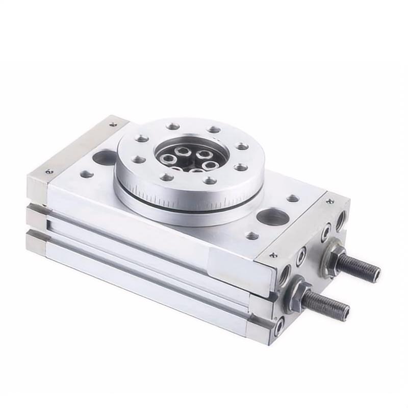
The term bore is also less universal than it appears. In a conventional rack actuator it normally means piston diameter. In rotary tables and vane actuators, manufacturers may lead with a frame or size code instead. Before comparing two values, confirm what the catalog’s size number actually represents.
For the linear force side of the relationship, see our practical guide to cylinder bore size, force, and speed. The extra rotary step is converting that force through the actuator’s real mechanism.
When Does Doubling Bore Produce Four Times the Torque?
Doubling bore produces four times theoretical torque only in a controlled same-geometry comparison. At 6 bar, a hypothetical 40 mm piston acting through a fixed 20 mm pinion radius produces about 15.1 N·m; an 80 mm piston under identical conditions produces about 60.3 N·m before losses.
The useful engineering test is not “Did bore double?” It is “Which terms in M = A x p x rp stayed fixed?” The table below separates a controlled scaling exercise from the data in Parker’s actual VRS/VRA family.
| Comparison at 6 bar | Bore | Piston area | Pinion pitch radius | Theoretical torque | Increase from 40 mm |
|---|---|---|---|---|---|
| Controlled geometry | 40 mm | 1,257 mm² | 20 mm | 15.1 N·m | 1.0x |
| Controlled geometry | 80 mm | 5,027 mm² | 20 mm | 60.3 N·m | 4.0x |
| Parker VRS/VRA catalog | 40 mm | Catalog basis | 20 mm | 15 N·m | 1.0x |
| Parker VRS/VRA catalog | 80 mm | Catalog basis | 27 mm | 81 N·m | 5.4x |
The controlled values use the theoretical formula and rounded metric conversions. The Parker rows are catalog values at 6 bar. They agree at 40 mm because the assumed pitch radius matches that model. At 80 mm, the production actuator uses a larger pinion radius, so torque grows more than area alone predicts.
The opposite can also happen. A larger-bore model can have a smaller effective radius, different seal loading, or a catalog torque value based on more conservative efficiency. Its torque increase may then be less than the area ratio. This is why bore is a useful predictor within a defined design, but not a substitute for the torque table.
Use a calculation to establish demand, then compare it with the selected actuator’s catalog curve or table. Our rotary calculator helps keep load torque, inertia, acceleration, efficiency, and allowance visible in one estimate.
How Does Rack-and-Pinion Geometry Change the Result?
Parker’s 32 to 125 mm VRS/VRA range lists 7.2 to 276 N·m at 6 bar, but its pinion pitch diameters also span 20 to 75 mm. Bore and pinion geometry therefore change together across the family (Parker VRS/VRA catalog, accessed July 17, 2026).
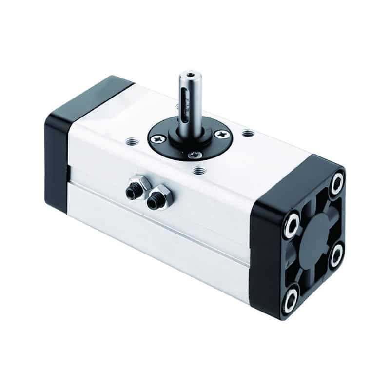
A larger pinion radius gives more torque for the same rack force, but it also changes rack travel needed for a given rotation. Designers balance torque, body length, angle, bearing arrangement, tooth loading, and package size. The final model is a mechanism, not just a piston in a tube.
Rack count matters too. A double-rack design applies force on opposite sides of the pinion and can raise torque while balancing tooth forces. It cannot be compared with a single-rack actuator by bore alone. Likewise, a rotary table may include bearings and an integrated table whose allowable moment loads become as important as shaft torque.
Mechanical loss must be handled using the manufacturer’s basis. Parker’s older application guide describes average rack-and-pinion efficiency of 85 to 90 percent, while the VRS/VRA product catalog instructs users to assure a maximum efficiency of 80 percent for functional losses. These are not contradictory universal constants. They are different guidance for different product documentation and assumptions.
For selection, use the catalog’s published effective or permissible torque where available. If only theoretical torque is shown, apply the manufacturer’s stated efficiency or service method. Do not quietly mix a theoretical value from one family with an efficiency percentage borrowed from another.
For a broader explanation of single-rack, double-rack, and vane construction, see rack-and-pinion versus vane rotary actuators.
Why Can’t Vane and Rack Actuators Share One Bore Rule?
SMC’s CRB2 vane catalog states that its double-vane version provides approximately twice the torque of the single-vane version with the same outside dimensions, except size 10. That change comes from mechanism configuration, not a doubled piston bore (SMC CRB2 catalog, accessed July 17, 2026).
A vane actuator develops torque as compressed air acts across one or more vanes. There is no rack force and pinion pitch radius to insert into the rack-and-pinion formula. Housing diameter, vane height, vane count, pressure area, and internal radius all participate in the result.
This creates a common catalog trap: a size 40 vane unit and a 40 mm bore rack actuator may share the number 40 but not the same pressure area, torque, or mounting envelope. Even two vane actuators labeled size 40 can differ if one is single vane and the other double vane.
Treat the size label as an index into the manufacturer’s data, not as a transferable torque specification. The only safe cross-mechanism comparison uses published torque at the same pressure, followed by separate checks for angle, backlash, end-stop behavior, shaft loading, and kinetic energy.
Choose the mechanism before optimizing bore. Rack-and-pinion actuators suit many precise, repeatable indexing tasks and can offer adjustable rotation. Vane units are often compact for their angle and package. Neither description proves suitability without application data. Our guide to how pneumatic rotary actuators work explains these operating differences before sizing begins.
How Should You Read Catalog Torque Data?
SMC labels the operating torque values in its low-speed CRQ2X and MSQX catalog as representative rather than guaranteed. It also notes that, without an external stopper, holding torque at the rotation end is half the table value (SMC low-speed rotary actuator catalog, accessed July 17, 2026).
First identify what kind of torque the table reports:
- Theoretical torque comes from pressure and ideal mechanism geometry before all practical losses.
- Effective or operating torque includes a manufacturer-defined allowance for internal loss or operating behavior.
- Holding torque describes resistance at a stopped position and may not equal moving torque.
- Permissible torque can be limited by shafts, keys, couplings, stops, or bearings rather than pressure area.
Next match the catalog pressure to the lowest actuator-inlet pressure while the load is moving. A compressor set to 7 bar does not prove that the actuator sees 7 bar during acceleration. Long tubing, undersized valves, restrictive fittings, simultaneous demand, and exhaust backpressure can reduce the available differential pressure. The CAGI pressure-drop brief recommends designing compressed-air piping for no more than 10 percent pressure drop between the compressor and point of use (CAGI pressure-drop technical brief, accessed July 17, 2026).
Measure pressure at both actuator ports during the problem part of the cycle when practical. Supply-side pressure alone can hide exhaust restriction. If pressure is unstable, correct the distribution or valve problem before buying a larger actuator. Our pressure-drop troubleshooting guide covers that system-level check.
Finally, confirm whether catalog torque is quoted at the shaft throughout rotation or at a test point. Read footnotes on rotation speed, cushions, stops, temperature, lubrication, and duty. A bold torque number without its test conditions is not yet a selection value.
What Trade-offs Grow With Bore Size?
Larger actuators consume more air and add mass. In Parker’s VRS/VRA family, actuator weight rises from 2.2 kg at 40 mm bore to 6.2 kg at 80 mm bore, while theoretical torque rises from 15 to 81 N·m at 6 bar (Parker VRS/VRA catalog, accessed July 17, 2026).
More bore area means more compressed volume per stroke when rack travel is comparable. A larger model may also use longer piston travel, a larger pinion, or two racks. The valve and tubing must fill and exhaust that volume within the required movement time. Oversizing can therefore produce a slow actuator if the flow path is unchanged, or a harsh actuator if flow is increased without adequate deceleration.
The main trade-offs are not all proportional:
| Check | Why a larger model can change it | What to verify |
|---|---|---|
| Air consumption | More internal volume must be charged and exhausted | Catalog displacement or air-consumption data at actual pressure and cycle rate |
| Valve flow | Larger transient demand increases pressure drop | Valve flow curve, tube length, fitting restrictions, exhaust silencer condition |
| Moving mass | Larger pistons, racks, housing, and table add inertia | Acceleration time, mounting stiffness, robot payload if applicable |
| Stopping energy | More available torque can accelerate the load harder | Allowable kinetic energy, cushion setting, shock absorber, external stop |
| Shaft and bearing load | A larger body does not automatically permit every overhung load | Axial, radial, and moment-load limits at the real attachment point |
| Footprint and cost | Envelope, mounting pattern, and accessory sizes grow | CAD clearance, maintenance access, total installed cost |
Stopping energy deserves its own calculation. SMC warns that kinetic energy can damage internal parts even when required load torque is small, and its low-speed catalog lists allowable kinetic energy from 0.00025 to 0.081 J depending on series and size. Parker’s XR guide similarly requires kinetic energy and torque to be considered together (Parker XR rotary actuator catalog, accessed July 17, 2026).
A bore increase can solve a torque deficit while creating a stopping problem. If the current actuator reaches the endpoint violently, diagnose speed control, load inertia, cushion capacity, and stop placement before selecting more torque.
A Bore-to-Torque Selection Workflow
Parker’s PRO/PRN method adds resistance torque and acceleration torque, then compares the result with effective torque at operating pressure. SMC separately requires checks for rotation time and allowable kinetic energy. A reliable workflow keeps these requirements distinct instead of hiding them inside one safety factor (Parker PRO/PRN guide, accessed July 17, 2026).
-
Define the motion. Record start and end angles, direction, move time, dwell, cycles per minute, and required positioning behavior.
-
Build the load model. Include external resistance, gravity, friction, fixture mass, workpiece mass, center-of-gravity radius, and moment of inertia. Mass at a large radius often controls acceleration more than total mass suggests.
-
Calculate demand torque. Add resistance torque and
J x alpha. For a process valve, use valve breakaway, running, and seating torque from the valve supplier instead of estimating them from handle force. -
Establish minimum dynamic pressure. Measure or conservatively estimate pressure at the actuator during the fastest or heaviest part of the move. Include exhaust backpressure when it is material.
-
Choose a mechanism family. Filter by rotation angle, package, backlash, mounting, shaft interface, environmental requirements, and load support before comparing sizes.
-
Use the catalog torque basis. Compare demand with effective or operating torque at the minimum dynamic pressure. If the manufacturer specifies a service factor or efficiency method, use that method and record it.
-
Check energy and loads separately. Verify allowable kinetic energy, rotation-time range, radial load, axial load, moment load, stops, cushion capacity, and duty life. Passing the torque check does not make these checks pass.
-
Validate on the machine. Confirm pressure at both ports, cycle time, endpoint behavior, repeatability, and temperature under worst-case production conditions. Lock the approved regulator, valve, tube, fitting, and speed-controller configuration into the bill of materials.
This article focuses on how bore affects output. For the full load, inertia, valve-flow, and commissioning process, use our engineer’s guide to sizing pneumatic rotary actuators. A second worked method is available in how to calculate rotary actuator torque requirements.
In our experience reviewing rotary-actuator applications, the most useful request is not “quote a 63 mm rotary actuator.” It is a short worksheet containing load geometry, move time, angle, dynamic pressure, mounting, and stopping method. That information lets us compare mechanisms and catalog sizes without pretending the bore label answers the entire application.
What Belongs on the RFQ?
Parker offers VRS/VRA bore sizes from 32 to 125 mm and rotation versions of 96, 186, and 366 degrees. Those options show why an RFQ needs more than bore and torque: rotation, pressure, interfaces, and stopping conditions select the actual configuration (Parker VRS/VRA catalog, accessed July 17, 2026).
Send the supplier enough information to reproduce your selection assumptions:
- Application and load description
- Required rotation angle and adjustment range
- Required cycle time and cycles per minute
- Load mass, dimensions, center of gravity, and moment of inertia
- Static resistance, gravity, friction, and process torque where applicable
- Minimum measured supply pressure during movement and expected exhaust backpressure
- Required output torque and the calculation method used
- Shaft, key, flange, coupling, and mounting requirements
- Radial, axial, and moment loads at their actual distances from the shaft
- Internal cushion, shock absorber, or external-stop arrangement
- Temperature, contamination, washdown, corrosion, and hazardous-area conditions
- Position sensing, solenoid voltage, speed controls, and fail-position requirements
Ask the supplier to state whether the proposed torque is theoretical, effective, operating, or permissible. Also request the pressure basis, relevant efficiency or service factor, allowable kinetic energy, shaft-load limits, air consumption, and recommended valve flow. This turns a vague “bore size” inquiry into a selection that can be checked and commissioned.
Conclusion: Bore Starts the Calculation, Catalog Data Finishes It
Parker’s 40 and 80 mm VRS/VRA models demonstrate the central point: doubling bore accompanies a 5.4 times torque increase at 6 bar because pinion radius changes too. Bore predicts pressure area, while catalog geometry and operating conditions determine usable rotary output (Parker VRS/VRA catalog, accessed July 17, 2026).
Use the diameter-squared rule to understand a controlled design, not to jump between product series. For a real machine, calculate resistance and acceleration torque, establish the lowest dynamic pressure, select the mechanism, and compare against model-specific effective torque. Then check stopping energy, shaft loads, rotation time, airflow, and duty.
If you send us the load geometry, angle, movement time, pressure, and mounting constraints, we can help distinguish whether the application needs more bore, different gearing, a double-rack or double-vane mechanism, better airflow, or improved deceleration. The right answer is often more specific than “choose the next bore size.” Use the contact page to request an application review.
FAQs About Rotary Actuator Bore Size
SMC’s CRB2 catalog shows why common bore questions need mechanism context: a double-vane version can deliver about twice the torque of a single-vane version at nearly the same outside dimensions. These answers therefore separate controlled scaling rules from model-specific selection (SMC CRB2 catalog, accessed July 17, 2026).
Does doubling rotary actuator bore always quadruple torque?
No. It quadruples piston area, and therefore theoretical torque, only if pressure, pinion radius, rack count, and efficiency stay constant. In an actual catalog family, those variables may change with size. Use the diameter-squared relationship as a controlled comparison, then verify the selected model’s published torque.
Can I compare a vane actuator and a rack-and-pinion actuator by bore?
Not reliably. A rack actuator converts piston force through a pinion radius. A vane actuator uses pressure acting through vane geometry. Size labels may not even mean the same physical dimension. Compare catalog torque at the same operating pressure, then check angle, backlash, shaft loads, rotation time, and kinetic energy.
Should I use theoretical torque or effective torque for selection?
Use effective or operating torque when the manufacturer publishes it for the stated conditions. If the catalog only provides theoretical torque, apply that manufacturer’s documented efficiency, service factor, or selection method. Do not borrow a generic loss percentage from another actuator family.
Why does a larger-bore actuator still stall?
The actuator may see less pressure during motion than the regulator gauge suggests. Valve restriction, long or narrow tubing, fittings, simultaneous demand, and exhaust backpressure can reduce differential pressure. It can also stall because load torque, gravity, friction, or acceleration was underestimated. Measure both port pressures during the event before resizing.
Is a larger bore always safer?
No. A larger actuator can increase air consumption, mass, acceleration, endpoint impact, valve-flow demand, footprint, and cost. It still must pass kinetic-energy, shaft-load, cushion, stop, rotation-time, and duty checks. Choose the smallest catalog model that passes every documented requirement with the manufacturer’s prescribed allowance.
Source Notes
- Parker VRS/VRA Rotary Actuators Catalogue, bore, torque, pinion, pressure, weight, and rotation data. Retrieved July 17, 2026.
- Parker Rotary Actuator Application Guide, rack-and-pinion torque relationship and efficiency guidance. Retrieved July 17, 2026.
- Parker PRO/PRN Pneumatic Rotary Actuator Guide, resistance and acceleration torque selection workflow. Retrieved July 17, 2026.
- Parker XR Rotary Actuator Catalog, torque, displacement, friction, and kinetic-energy guidance. Retrieved July 17, 2026.
- SMC CRB2 Rotary Actuator Catalog, single-vane and double-vane design data. Retrieved July 17, 2026.
- SMC Low-Speed CRQ2X/MSQX Catalog, operating torque, holding torque, rotation time, and kinetic-energy guidance. Retrieved July 17, 2026.
- CAGI Pressure Drop Technical Brief, compressed-air distribution pressure-drop guidance. Retrieved July 17, 2026.