

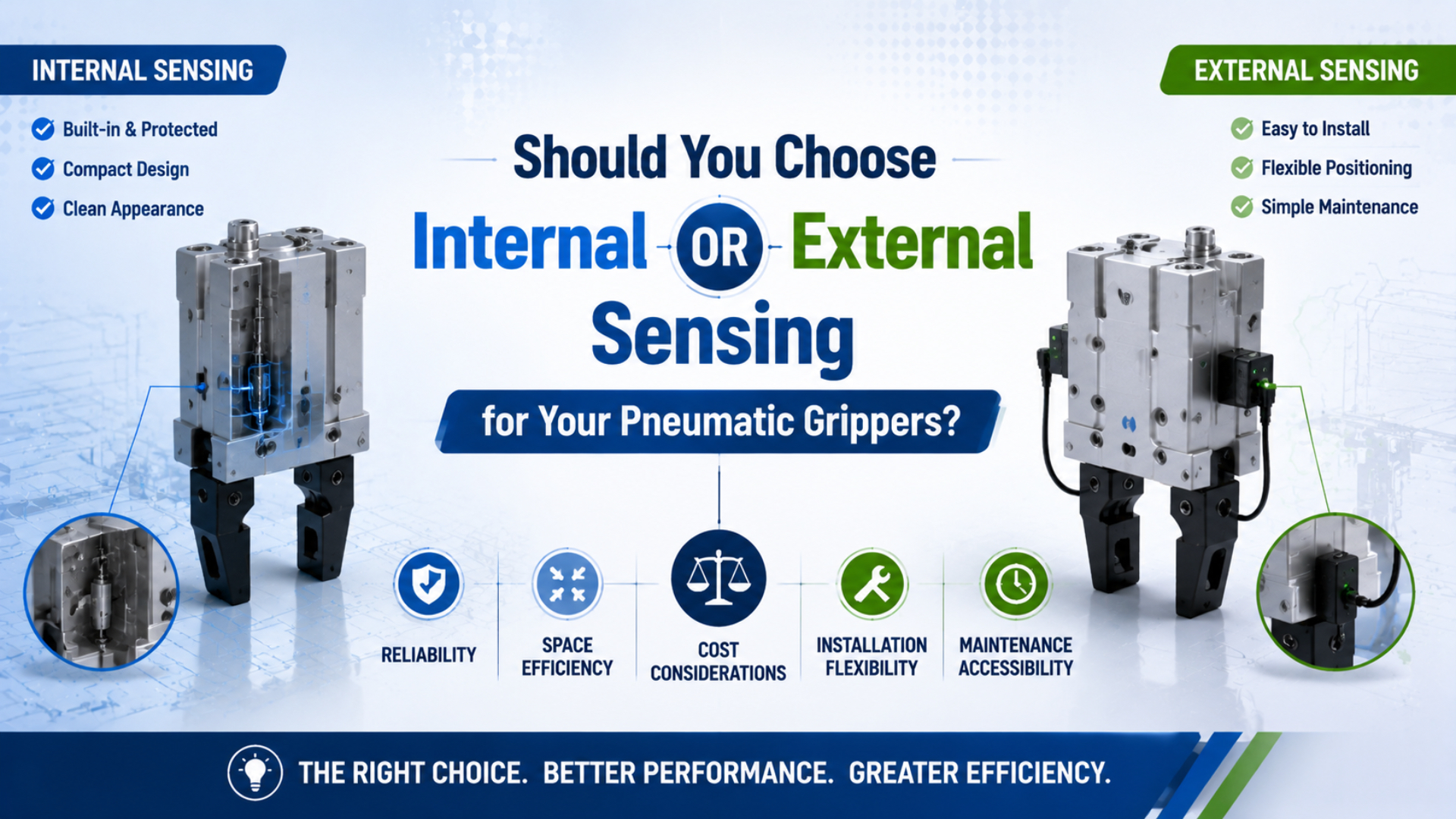
Choose internal sensing when the PLC only needs a compact, protected indication of the gripper’s drive position. Choose external sensing when the machine must observe a jaw, target, or workpiece directly. If a missed part matters, use both. Each signal must prove a different condition.
The mounting label alone isn’t enough. A slot-mounted magnetic sensor may sit outside the housing while reading a magnet inside the drive. An external photoelectric sensor can see the workpiece without knowing whether the jaws produced enough holding force. Start with the physical state the machine must trust, then select the sensor.
Key Takeaways
- SICK documents three gripper states: open without an object, object gripped, and closed without an object.
- Internal sensing tracks the drive, not force.
- External sensing can observe the jaw or workpiece, but its bracket, target, cable, material response, and contamination limits become part of the measurement.
- Fault-test the installed system.
What Does Internal Sensing Actually Confirm?
SICK’s 2025 MPS-G instructions define three gripper states that one device can distinguish: open without an object, object gripped, and closed without an object (SICK MPS-G Operating Instructions, 2025). Those states come from magnet position, so the signal confirms a mechanism position or taught window rather than contact force by itself.
In this article, internal sensing means a sensor arrangement that reads the gripper’s built-in drive or finger-position mechanism. The sensing head may fit into a C-slot or T-slot on the body, yet the measured target is still the internal piston, wedge, rack, or magnet. That distinction matters when fingers are long, compliant, worn, or removable. The piston can enter its taught zone while a loose finger shifts, and a thin part can slip after the PLC accepts the first signal. The sensor hasn’t failed. It reported the datum it was designed to observe. In our experience, clear PLC tags speed fault finding. Use gripper_drive_in_part_window instead of a vague label such as part_ok.
Use an internal signal to answer narrow questions:
- Did the drive move?
- Did it enter the taught grip window before timeout?
- Did it reach the fully closed position with no workpiece between the fingers, indicating empty close rather than a successful grip?
- Did the signal remain stable through transfer?
If the PLC needs general endpoint or continuous position feedback beyond grippers, compare reed switches, solid-state switches, LVDTs, and encoders in the pneumatic cylinder position sensing guide.
What Can External Sensing Prove?
SCHUNK’s FPS system can teach up to five jaw-position regions by detecting a magnet installed in the gripper (SCHUNK FPS Flexible Position Sensor, 2026). An external arrangement can instead point at a finger, moving target, fixture, or part, placing the measurement closer to the process result the PLC must judge.
External sensing means the sensing element and target are mounted outside the gripper’s internal drive path. Common choices include an inductive sensor aimed at a metal flag, a photoelectric sensor looking for the workpiece, or a separate position device measuring jaw travel. Each sees a different datum.
Would a jaw-position sensor prove that a flexible pouch is still between the fingers? Not necessarily. Jaw position may show that the opening matches the recipe.
A through-beam or diffuse photoelectric sensor can confirm actual presence. Conversely, an optical sensor may detect a part in the nest while the gripper remains open. They prove different facts.
External sensing adds adjustment freedom. It also adds a bracket, fasteners, target alignment, exposed cable, and environmental path. Those items belong in the fault analysis. A sensor with perfect electrical repeatability can still switch at the wrong point after its bracket moves.
Match the Sensor to the PLC Decision
SMC’s D-MH1 analog auto-switch system can discriminate up to three position points and lists a 0.2 mm dimensional difference in its high-resolution range (SMC Air-Gripper Auto Switches, 2026). That capability is valuable only when the taught positions correspond to distinct machine decisions.
Write the required PLC decision before selecting the part number. “Sense the gripper” is too vague for a controls drawing or RFQ. “Reject the cycle when the gripper reaches the empty-close window” is testable. For example, a drive sensor can prove that the mechanism entered a taught window, an optical sensor can prove that a part interrupts a beam, and a pressure switch can prove that pressure crossed a set point. None of those statements proves holding force alone. In our experience, assigning one physical noun to every PLC input prevents many sequence arguments later: drive, jaw, part, fixture, or pressure. It also gives the commissioning technician a clear target for each forced-fault test.
Mechanism and grip states
| PLC decision | Physical datum to observe | Suitable sensing approach | Important limitation |
|---|---|---|---|
| Gripper is fully open | Piston, wedge, or jaw at open position | Internal magnetic switch or jaw-position sensor | Does not prove the pickup area is clear. |
| Workpiece is inside the expected size window | Jaw or drive position during grip | Taught magnetic position sensor or external jaw target | A correct window does not prove holding force. |
| Gripper closed without a part | Fully closed mechanism position | Internal empty-close switch or position window | Requires enough separation from the valid grip window. |
Part, seating, and pressure states
| PLC decision | Physical datum to observe | Suitable sensing approach | Important limitation |
|---|---|---|---|
| Workpiece is physically present | Workpiece surface or interrupted beam | Photoelectric, inductive, capacitive, or vision sensor | Material, color, reflectivity, shape, and contamination affect selection. |
| Part is seated against a datum | Workpiece-to-fixture clearance | Gap sensor, air-catch sensor, or dedicated contact check | Seating is not the same as gripper force. |
| Pneumatic pressure crossed a limit | Pressure at the selected circuit point | Pressure switch or transmitter | Pressure alone doesn’t reveal jaw contact or friction. |
Treat these signals as separate evidence channels. A mechanism-position signal describes the gripper. A part-present signal describes the workpiece. A pressure signal describes the air circuit. Combining them in PLC logic can strengthen a decision, but renaming one signal cannot make it measure another physical quantity.
For geometry selection before sensing design, review the tradeoffs between parallel and angular pneumatic grippers and the broader guide to pneumatic gripper types.
When Is Internal Sensing the Better Fit?
ifm states that its IO-Link cylinder sensors can measure piston location continuously on short-stroke cylinders of 50 mm or less (ifm Cylinder Sensors, 2026). A body-slot sensor is a strong fit when the gripper provides a compatible magnet and slot, while the controller needs position states without an exposed target bracket.
Choose internal or body-slot sensing when compact packaging and protected mounting matter more than direct observation of the workpiece. It works well on repeatable parts where the grip window has clear separation from both open and empty-close positions.
The practical advantages are specific:
- The sensor stays with the gripper.
- A recessed head is less exposed to collision than a projecting bracket.
- Because the manufacturer defines the magnet path and slot, the target relationship doesn’t depend on a separate machine-frame flag or adjustable bracket.
- Short moving cable runs can simplify robot wrist packaging.
- On compatible devices, several taught points can replace multiple discrete switches and reduce separate mounting locations.
Check the limitations before committing. Confirm the exact slot profile, magnet, allowable sensing range, cable exit, connector, controller input, and taught-window resolution. A sensor advertised for a gripper family may not fit every size or option. Ferromagnetic chips and nearby magnetic fields also deserve review because SCHUNK warns that magnets, welders, motors, and magnetized material can influence its FPS system.
Internal sensing is not automatically harder to maintain. Some modern sensor heads slide into an accessible body slot. Nor is it automatically cheaper or longer-lived. Compare exact models, mounting time, cable replacement, spare strategy, and fault access instead of applying a universal percentage.
When Does External or Hybrid Sensing Win?
SICK describes photoelectric sensors as devices for object detection and presence sensing that use interrupted or reflected light (SICK Photoelectric Sensor Selection, 2024). That independent view is useful when a valid jaw position still cannot prove that the intended workpiece is present.
Choose external sensing when the process datum lies beyond the gripper drive. Typical examples include a removable finger tip, a compliant pad, a part with wide dimensional variation, or a fixture seat that must be checked independently. External mounting also helps when the gripper lacks a compatible magnet or sensor slot.
A hybrid arrangement uses two signals with different failure boundaries. For example, a body-slot sensor can confirm the taught grip window while a photoelectric sensor confirms part presence. If they disagree, the PLC stops the transfer and records which condition failed. This is better than wiring two sensors to the same target and calling the result independent. In our experience, useful hybrid logic starts with a fault sentence: “The jaws can reach the normal window even when the part is missing.” That sentence tells you what the second sensor must observe. It also provides a direct commissioning test. The extra sensor earns its place only when it closes a documented gap that the first measurement cannot see.
Don’t assume redundancy makes a safety function. ISO 13849-1:2023 defines a methodology for designing and integrating safety-related control systems across electrical, pneumatic, mechanical, and other technologies (ISO 13849-1, 2023). OSHA also treats an end effector such as a gripper as part of the industrial robot system (OSHA Technical Manual, Section IV, Chapter 4, 2026). A safety-related grip or retention function needs a risk assessment, required performance level, suitable architecture, diagnostics, and validation beyond normal process monitoring.
Which Environmental and Electrical Details Decide the Fit?
IEC 60529 classifies enclosure protection using the IP Code, while the current consolidated publication includes the base standard and amendments through 2013 (IEC 60529, 2013). An “internal” label doesn’t establish an IP rating. Verify the exact sensor, connector, cable entry, gripper, and assembled installation.
Environment can reverse an otherwise sensible choice. A recessed magnetic sensor may suit an oily machining cell, but ferrous chips can disturb magnetic sensing or conceal a setup problem. A photoelectric sensor avoids that magnetic target, yet coolant film, dust, transparent plastic, black surfaces, or background reflections may reduce detection margin.
Review these items together:
| Detail | Internal or slot-mounted check | External check |
|---|---|---|
| Mechanical fit | Slot geometry, sensor-head length, magnet compatibility, insertion direction | Bracket stiffness, target size, adjustment range, collision envelope |
| Electrical interface | PNP/NPN, normally open/closed, analog range, IO-Link port mode | Same checks plus any amplifier, reflector, or remote evaluation unit |
| Cable | Exit direction, wrist motion, bend radius, replacement access | Clamp spacing, flex zone, snag risk, connector exposure |
| Environment | Magnetic field, ferrous chips, housing material, stated IP rating | Target contamination, optical background, washdown, vibration, stated IP rating |
| Service | Teach access, replacement without removing tooling, stored parameters | Bracket datum, replacement alignment, teach procedure, target inspection |
Route sensor cables so movement doesn’t load the sensing head or connector. Keep low-level analog wiring away from solenoid coils, weld cables, and variable-frequency-drive conductors. For moving tooling, coordinate the cable path with the pneumatic tubing routing plan, then verify both routes at full wrist travel, maximum approved speed, and the tightest bend.
How Should You Program the Sequence?
SICK’s MPS-G can provide up to 16 switching points through IO-Link and can also report diagnostics such as temperature, orientation, vibration, and maximum acceleration (SICK MPS-G Operating Instructions, 2025). More data helps only when the PLC defines valid transitions, timeouts, and contradictory states.
Use state logic rather than a single permissive bit. A practical grip sequence may look like this:
- Confirm open and pickup-ready states.
- Verify the workpiece is present at the pickup datum.
- Command close and start a motion timeout.
- Require the open signal to clear within a defined time.
- Accept the grip only when the position enters the recipe window, the independent part signal remains valid, and no contradictory or diagnostic bit is active.
- Reject an empty-close signal, impossible signal combination, or expired timeout.
- If a dropped part must be detected before placement, continue monitoring through acceleration, travel, deceleration, and arrival.
- At release, confirm the part left the gripper and the mechanism returned to open.
The empty-close state is often more useful than a generic closed signal. It gives the PLC an explicit signature for “the mechanism completed its stroke, but no acceptable part stopped the jaws.” That diagnosis separates a pickup miss from a valve, air-supply, or motion fault.
Store the taught limits by recipe when part sizes change. Protect them from casual editing, and record the sensor model, parameter set, PLC scaling, debounce or filter time, and timeout values. If feedback becomes continuous position data rather than discrete states, the actuator feedback integration guide explains scaling, timing, and error-budget boundaries.
Commissioning Tests That Expose False Confidence
SMC lists 1-to-5 V analog output and as many as three discriminated position points for its D-MH1 system, but it also notes that converted stroke values depend on the actuator (SMC Air-Gripper Auto Switches, 2026). Commissioning must therefore test the installed gripper, fingers, parts, wiring, and PLC thresholds as one system.
Start with raw inputs. Move the gripper slowly through its full travel and record the actual switch points from both directions. Check hysteresis, repeatability, mechanical stop clearance, and whether a valid grip window overlaps the empty-close state. Then test at production speed and at the lowest approved dynamic pressure. For instance, an empty-pick run should reach the empty-close state without producing part_ok; the smallest acceptable part should stay outside that empty window at normal speed and minimum approved pressure. In our experience, these two boundary tests reveal more than repeated cycles with a nominal part. They challenge the decision limits instead of merely proving that the mechanism can move.
Use representative fault parts, not only nominal samples:
- Prove empty close.
- Test the smallest and largest acceptable parts.
- Where relevant, test undersize, oversize, skewed, double-fed, reflective, transparent, contaminated, and damaged parts across the allowed presentation range.
- Reduce pressure to the alarm boundary and verify the response.
- Unplug or break each sensor circuit in a controlled test.
- Move an external bracket by the smallest credible amount, then confirm that startup validation or the first challenged cycle catches the shifted datum.
- Contaminate the target or lens within the expected process condition.
- During transfer, interrupt the part-present signal at several motion phases and verify the defined stop, reject, alarm, and recovery behavior.
Repeat tests after changing fingers, pads, brackets, sensors, cables, recipes, PLC code, pressure settings, or gripper position. Why repeat them after a cable replacement? Because connector pinout, routing stress, and input polarity can change the failure response even when the mechanical setup looks untouched.
Record acceptance limits and results. A maintenance technician should be able to distinguish a missing part, wrong part, sensor alignment fault, cable fault, pressure problem, and gripper wear without guessing from one “grip failed” alarm.
FAQs About Pneumatic Gripper Sensing
SICK’s documented three-state example separates open without an object, object gripped, and closed without an object (SICK MPS-G Operating Instructions, 2025). The answers below keep mechanism position, jaw position, workpiece presence, pressure, and safety validation separate.
Does an internal gripper sensor prove that a part is present?
Not by itself. A magnetic sensor normally reads a drive magnet or a position derived from the drive. A taught grip window can infer that an object stopped the jaws, but finger looseness, part slip, or another obstruction can create a similar position. Add independent part detection when the consequence justifies it.
Is external sensing always more accurate?
No. Accuracy depends on the complete measurement path, including the target, bracket, alignment, switching hysteresis, environment, cable, controller input, and test method. External sensing can be closer to the workpiece datum, but a moving bracket or contaminated optical target can make the resulting decision less reliable.
Can a pressure switch confirm gripping force?
A pressure switch confirms pressure at its connection point and threshold. It doesn’t directly measure finger force, friction, contact geometry, or whether a part remains between the jaws. Use pressure as circuit evidence. Establish holding performance through force calculations, catalog data, and tests with representative parts and motion.
How many gripper positions can one sensor monitor?
The count depends on the device and interface: SMC lists up to three discriminated points for its D-MH1 system. SICK’s MPS-G supports two or three discrete points and up to 16 through IO-Link, while SCHUNK’s FPS can teach five regions. Confirm usable separation on the actual gripper.
Should a safety-related gripper use internal and external sensors?
Not as a universal rule. ISO 13849-1:2023 requires a design and integration method for safety-related control parts but doesn’t prescribe the safety function or required performance level for every machine. Define the hazard and safe state first. Then select architecture, diagnostics, components, and validation for the required result.
What Should You Specify Before Ordering?
SCHUNK notes that the FPS resolution is commonly 1% to 3% of jaw stroke with many compatible grippers, while some designs reach only 10% (SCHUNK FPS Flexible Position Sensor, 2026). A useful RFQ must therefore identify the exact gripper, stroke, fingers, workpiece windows, and required state separation.
Send the supplier or integrator enough information to reproduce the decision:
- Exact gripper model and size
- Finger drawing, gripping point, part materials, and the full acceptable size range, including the smallest separation from empty close
- Every state the PLC must distinguish
- Required response time, cycle rate, and motion timeout under production conditions
- Controller input type, voltage, PNP/NPN logic, analog range, or IO-Link master
- Cable length, connector, flex duty, dress-pack path, replacement access, and approved bend radius
- Environmental limits: coolant, chips, dust, washdown, temperature, vibration, magnetic fields, enclosure rating, and cleaning chemicals that contact cable jackets, seals, reflectors, or lenses
- Teach method and recipe count
- Acceptance tests covering nominal and limit parts, empty pickup, pressure loss, shifted brackets, contamination, and signal faults
Keep the sensor set simple. Internal sensing is usually the cleanest way to monitor the mechanism. External sensing is valuable when the jaw, part, or fixture is the real datum. A hybrid design earns its extra cost only when the two channels close different, documented failure gaps that commissioning can reproduce.
For a control review, send the gripper model, finger drawing, workpiece limits, PLC I/O, sensor preferences, environment, and fault-response requirements through the technical contact page.
Eric Zhou prepared this guide from a pneumatic-controls perspective. The About Bepto page explains the engineering background behind this technical library.
Sources
Eight primary technical sources support this guide. The most detailed is SICK’s 2025 MPS-G instruction manual, which documents two or three discrete switching points and up to 16 points through IO-Link. Product capabilities are model-specific, so the linked documents should be checked against the exact part number before purchase.
-
SICK, MPS-G with Switching Points and IO-Link Operating Instructions: Supports the three gripper states, switching-point counts, IO-Link position measurement, diagnostics, operating principle, and installation limits. Retrieved 2026-07-17.
-
SMC, Air-Gripper Auto Switches: Supports D-MH1 analog output, three-point discrimination, 0.2 mm high-resolution dimensional difference, workpiece-state examples, and D-MH2 IO-Link options. Retrieved 2026-07-17.
-
ifm, Cylinder Sensors: Supports magnetic piston detection through a non-magnetizable housing, slot mounting, adapters, and continuous position measurement for short strokes of 50 mm or less. Retrieved 2026-07-17.
-
SCHUNK, FPS Flexible Position Sensor: Supports five taught jaw-position regions, digital outputs, magnetic-interference cautions, and model-dependent resolution as a percentage of jaw stroke. Retrieved 2026-07-17.
-
SICK, Photoelectric Sensor Selection: Supports photoelectric object detection, presence sensing, material and environment checks, and output selection. Retrieved 2026-07-17.
-
IEC, IEC 60529 Degrees of Protection Provided by Enclosures: Supports the scope and current consolidated publication of the IP Code standard. Retrieved 2026-07-17.
-
ISO, ISO 13849-1:2023: Supports the methodology and scope for design and integration of safety-related control parts across electrical, pneumatic, mechanical, and other technologies. Retrieved 2026-07-17.
-
OSHA, Technical Manual Section IV, Chapter 4: Supports treating an end effector such as a gripper as part of an industrial robot system and keeping process sensing separate from robot-system safety measures. Retrieved 2026-07-17.