

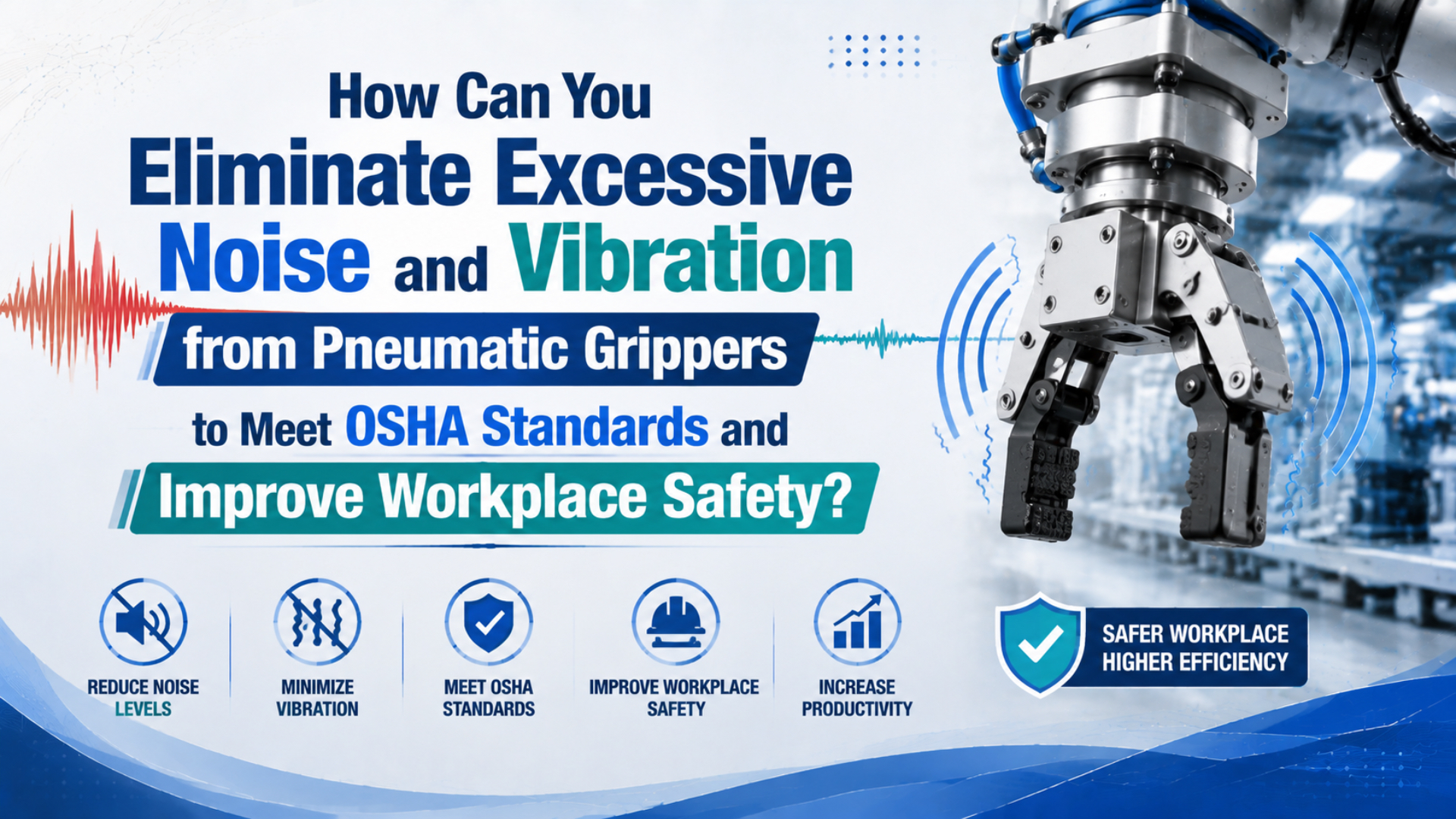
You reduce excessive pneumatic gripper noise and vibration by measuring worker exposure first, separating exhaust noise from jaw impact and structure-borne vibration, and then controlling the dominant source. The fix might be a correctly sized exhaust muffler, lower impact speed, repaired fingers, a quieter valve arrangement, or an engineered mount. It is rarely one universal “low-noise kit.”
OSHA compliance is based on employee noise exposure, not the sound rating of one gripper. A quiet reading beside the gripper doesn’t replace an exposure assessment, and a lower-pressure setting isn’t safe until the gripper still provides enough force at the real finger length and acceleration.
Key Takeaways
- OSHA’s hearing-conservation action level is 85 dBA over 8 hours; its general-industry PEL is 90 dBA over 8 hours.
- Diagnose exhaust, impact, valve, leakage, and structural paths separately.
- Recheck grip force, cycle time, repeatability, and worker exposure after every control change.
What Do OSHA and NIOSH Actually Require for Workplace Noise?
OSHA’s hearing-conservation action level is an 8-hour TWA of 85 dBA; its general-industry PEL is 90 dBA over 8 hours. NIOSH recommends 85 dBA with a more protective 3 dB exchange rate (OSHA, 2026; NIOSH, 2024).
Those numbers answer different questions:
| Limit or reference | Meaning | Exchange rate |
|---|---|---|
| OSHA 85 dBA, 8-hour TWA | Hearing-conservation action level | 5 dB |
| OSHA 90 dBA, 8-hour TWA | General-industry permissible exposure limit | 5 dB |
| NIOSH 85 dBA, 8-hour TWA | Recommended exposure limit | 3 dB |
| OSHA 140 dB peak | Ceiling stated for impulsive or impact noise | Not a daily TWA |
An 85 dBA reading during one gripper cycle does not automatically prove compliance or noncompliance. Duration, repetition, other machines, worker movement, production mix, and shift length all contribute to the employee’s dose. OSHA also requires continuous, intermittent, and impulsive sound from 80 to 130 dB to be integrated into exposure measurements when the standard applies.
Employee noise exposure is the sound dose or TWA received by a worker over the measured period. Task sound level is a repeatable engineering measurement used to compare an operation or control. A task reading helps diagnosis, but it does not replace representative personal exposure sampling.
For an operating U.S. facility, the employer and qualified safety professional must apply the correct OSHA standard, state-plan requirement, collective agreement, and site policy. NIOSH recommendations are useful prevention targets, but they are not the same as OSHA’s enforceable PEL.
What about vibration? OSHA’s technical manual says the agency does not have a general vibration-exposure standard. Gripper vibration still matters because it can radiate noise, loosen tooling, reduce positioning stability, or signal a fault, but don’t label a machine-mount acceleration value as an “OSHA vibration limit.”
Measuring a Noisy Pneumatic Gripper Station
OSHA requires calibrated instruments and representative personal sampling when worker mobility, changing sound levels, or impulse noise make area measurements inadequate. A noise dosimeter measures exposure across a task or shift, while a sound level meter and octave-band analyzer help locate dominant frequencies and sources (OSHA Technical Manual, 2022).
Use two measurement layers.
Exposure measurement answers whether workers enter a hearing-conservation or overexposure condition. Place a dosimeter microphone in the worker’s hearing zone and document the shift, tasks, production state, breaks, and nearby equipment. The sampling plan should represent the people and conditions being evaluated.
Engineering measurement answers what to fix. Use a calibrated sound level meter at repeatable locations, then add octave-band or one-third-octave analysis when the frequency content can distinguish exhaust hiss from mechanical impact or structural radiation.
Record these conditions for every before-and-after comparison:
- instrument, calibration check, weighting, response, range, and sampling duration
- microphone location, height, distance, and orientation
- worker position and machine guarding state
- gripper model, finger tooling, workpiece, pressure, cycle rate, and load
- valve, flow-control, exhaust, and muffler configuration
- other equipment running in the area
- background level and whether the cycle includes distinct impact peaks
- production mode, not just manual jogging
Would a phone application be enough? It can help locate a change or compare two maintenance states, but it is not a substitute for the calibrated instrument and sampling strategy needed for a compliance decision.
Synchronize the sound trace with the machine sequence. A time marker for valve energization, jaw contact, part release, and arm acceleration turns one overall dBA value into a diagnostic timeline. Without timing, a loud exhaust pulse and a jaw collision can look like the same fault.
Which Part of the Gripper System Is Producing the Noise or Vibration?
OSHA’s standard octave-band set uses 11 center frequencies from 16 to 16,000 Hz, giving investigators a practical way to separate low-frequency structural radiation from higher-frequency air noise. The manual also recommends isolating components and comparing operating states to identify each source’s relative contribution (OSHA Technical Manual, 2022).
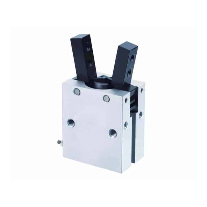
Inspect the entire end-of-arm assembly, not just the gripper body:
| Source | Typical clue | Safe isolation test | Likely control direction |
|---|---|---|---|
| Valve exhaust | Short hiss aligned with opening or closing | Compare exhaust ports and directions at controlled speed | Correctly sized muffler, smoother exhaust flow, valve relocation |
| Air leak | Continuous hiss during dwell | Isolate pressure safely and perform an approved leak test | Repair fitting, tube, seal, manifold, or valve |
| Jaw or finger end stop | Sharp repeatable impact at full travel | Cycle without a workpiece at reduced approved speed | Reduce approach speed, correct stroke use, inspect stop and guide |
| Finger-to-part contact | Impact appears only with the part | Compare no-load and loaded traces under guarded conditions | Change contact timing, pad, geometry, compliance, or speed |
| Valve coil or spool | Click occurs at command, before jaw motion | Compare electrical command and sound timing | Verify valve condition, mounting, voltage, and selected series |
| Loose finger or adapter | Rattle changes with direction or acceleration | Lock out and inspect fasteners, fits, cracks, and dowels | Repair interface and restore specified torque or location |
| Gripper guide or transmission | Roughness, uneven motion, rising vibration | Compare jaw motion, play, pressure, and service history | Clean, repair, or replace per the gripper manual |
| Robot wrist or frame | Low-frequency response continues after impact | Measure at gripper, adapter, wrist, and frame | Stiffen or isolate the correct interface after dynamic review |
Don’t remove guarding, bypass interlocks, or place hands near the fingers to “listen more closely.” Use remote measurements, safe reduced-speed modes, and the machine builder’s diagnostic procedure.
The parallel gripper operating guide explains how synchronized jaws, backlash, finger projection, and guide loads can affect motion. For broader gripper selection, use the pneumatic gripper types guide.
Reducing Exhaust Noise Without Slowing the Gripper
NIOSH says a 3 dB reduction in worker exposure can reduce hearing-loss risk, but a silencer must still pass the required exhaust flow. OSHA recommends optimizing air pressure first, then using an appropriate silencer when compressed-air noise remains significant (NIOSH, 2024; OSHA, 2022).
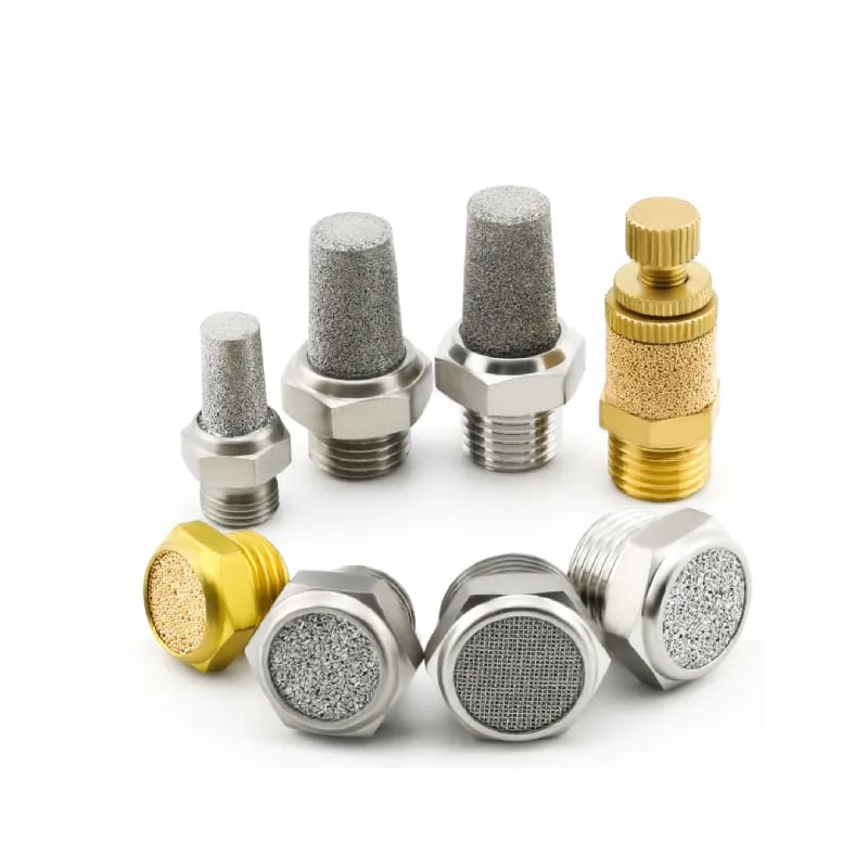
A muffler reduces the sharp discharge by expanding and distributing the exhaust through porous media, a diffuser, or an engineered chamber. It does not make the air volume disappear. If the passage is too small or becomes clogged, the gripper’s venting chamber retains pressure and the jaws can slow or move unevenly.
Select from the actual exhaust duty:
- valve exhaust port and permitted connection
- peak exhaust flow for opening and closing
- allowable back pressure and required jaw time
- measured sound spectrum and insertion-loss data
- oily, wet, dusty, cleanroom, washdown, or hot environment
- shared manifold exhaust versus one muffler per port
- maintenance access and replacement indication
Match each muffler to the valve and cycle, not thread size alone. A 1/4-inch connection does not describe internal flow area, acoustic performance, or loaded pressure drop.
What about a quick-exhaust valve? It can shorten an actuator’s exhaust path, but releasing a larger pulse near the gripper may increase local noise. Use one only when the motion requirement justifies it, then select and verify its exhaust treatment. It isn’t a universal noise-control component.
If a muffler change lowers dBA but increases jaw time, the control is incomplete. Measure opening and closing separately because each direction may use a different valve port or flow setting. The pneumatic muffler guide covers exhaust flow, back pressure, and muffler maintenance without repeating those details here.
How Can You Reduce Jaw Impact and Valve-Switching Noise?
OSHA states that impulsive or impact noise should not exceed 140 dB peak sound pressure level. Most gripper impacts will be below that ceiling, but repeated impact can still dominate the station’s spectrum, damage tooling, or reveal uncontrolled deceleration (OSHA 1910.95, 2026).
Start by determining which collision creates the pulse:
- base jaw reaching the gripper’s internal travel limit
- custom finger striking an external stop
- finger pad contacting the part too quickly
- part hitting a nest during release
- loose tooling reversing across clearance
- robot acceleration exciting the gripper adapter
Reduce energy at the source. Lower the closing or opening speed where cycle time permits, shorten unnecessary free travel, reduce moving finger mass, add approved compliant contact material, and correct the part or nest position. A softer pad can lower impact noise, but it also changes friction, deflection, repeatability, wear, cleanliness, and contact pressure.
Flow controls need the correct direction and adjustment. Meter-out control often produces stable pneumatic motion, but the selected gripper and valve manual govern the circuit. Do not stack an adjustable exhaust muffler, speed controller, small fitting, and undersized valve without checking the combined restriction.
Valve noise is a separate event. Check coil voltage, mounting rigidity, spool condition, pilot pressure, and switching frequency. Moving the valve away from the operator can change the sound path, but longer tubing may alter response, air volume, and pressure at the gripper. Verify the complete cycle after relocation.
Active noise cancellation is rarely the first control for a small gripper station. Exhaust and impact pulses vary with the cycle, while loose fingers and worn guides need repair. Fixing the physical source is usually more reliable than trying to cancel its sound downstream.
When Does Vibration Isolation Help, and When Can It Make Things Worse?
NIOSH warns that the wrong vibration mounts can increase vibration, even though correct isolation can reduce structure-borne noise. A 3 dB exposure reduction can still be meaningful, but isolators must be selected from supported mass, forcing frequency, natural frequency, damping, motion limits, and required positioning stiffness (NIOSH, 2024).
First decide whether the vibration is a symptom or a transmission path. A loose finger, cracked adapter, worn guide, off-center part, or unstable robot motion should be corrected at the source. Placing a soft mount under a defective assembly can hide the symptom while reducing positioning accuracy.
Measure vibration at several locations with a suitable accelerometer:
- gripper body
- finger or tooling plate where practical
- gripper adapter
- robot wrist or slide carriage
- nearby guard, panel, or frame that radiates sound
Compare amplitude and frequency at the same cycle speed. A strong component at jaw contact points toward impact excitation. A narrow peak that grows at one cycle rate suggests resonance. A broadband increase with rough jaw motion can indicate looseness, wear, or contamination.
Isolation works when the mount breaks a transmission path without putting the forcing frequency near the mounted system’s natural frequency. If positioning stiffness is critical, improve the source, add damping to a radiating panel, or stiffen the adapter before considering a softer interface.
Treat the gripper, adapter, wrist, and custom fingers as one dynamic assembly. Changing finger mass or length can move a resonance even when the gripper body and robot program are unchanged. The quietest mount in a bench test may not be the most stable mount during production acceleration.
For airborne path treatment, use barriers or enclosures only after source controls. Openings for parts, cables, air lines, moving equipment, and ventilation can dominate the installed result. Absorptive foam lowers reflections inside a space; it is not a substitute for a dense, sealed transmission barrier.
Can You Lower Air Pressure Without Losing Safe Gripping Force?
SMC publishes MHL2 effective-force curves from 0.1 to 0.6 MPa and defines force per finger at the actual gripping point. One example produces 73 N per finger at 0.5 MPa and 70 mm, showing why a generic “use 4 bar” rule is unsafe (SMC, 2026).
Lower pressure can reduce the energy available for exhaust and mechanical impact, but it also reduces actuator drive force. Before changing the regulator, calculate the force needed to retain the real part during the worst acceleration and orientation.
A preliminary friction-grip estimate is:
Required force per jaw = mass × (gravity + acceleration) × safety factor
                         / (friction coefficient × load-sharing jaws)
This estimate doesn’t include finger moments, guide limits, form-fit geometry, pressure transients, surface contamination, part variation, or shock. Use conservative inputs and then compare the result with the manufacturer’s effective grip-force curve at the actual pressure, opening or closing direction, and contact distance.
Pressure reduction is acceptable only if all of these still pass:
- required force at the actual contact position
- finger and guide force and moment limits
- part retention during emergency stop and maximum acceleration
- opening and closing time
- sensor switching and part-present logic
- repeatability and part damage limits
- minimum valve pilot pressure and gripper operating pressure
Don’t assume most systems are overpressurized. Measure dynamic pressure at the gripper while it closes on the part. A regulator may show 6 bar at rest while small tubing, a clogged filter, or simultaneous demand produces a much lower value during contact. The pressure-drop troubleshooting guide explains that test.
In our experience, finger projection is the pressure-reduction detail most often missed. A gripper can have enough nominal force at the base jaws but exceed its permitted moment or lose effective force at long custom fingers. The force curve and moment chart must be checked together.
Verifying Noise Controls Without Hurting Production
OSHA requires exposure instruments to be calibrated and directs employers to integrate continuous, intermittent, and impulsive sound from 80 to 130 dB when measuring employee exposure. A valid before-and-after test must therefore repeat the production condition, sampling method, worker position, cycle mix, and measurement settings (OSHA 1910.95, 2026).
Use an acceptance matrix instead of one dBA number:
| Acceptance item | Before | After | Pass criterion |
|---|---|---|---|
| Worker noise dose or TWA | Representative shift or task | Same production basis | Meets applicable exposure and site target |
| Task or cycle sound level | Fixed instrument and location | Same setup | Documented reduction with no new dominant peak |
| Opening and closing time | Loaded production cycle | Same part and pressure state | Within machine requirement |
| Grip force margin | Actual pressure and finger point | Updated force curve or test | Above approved minimum |
| Part retention | Worst orientation and acceleration | Repeat controlled validation | No slip or loss of safe state |
| Repeatability | Finished finger contact point | Same sample and conditions | Within process tolerance |
| Exhaust back pressure | Normal cycle | New muffler and settings | Within valve/gripper requirement |
| Vibration spectrum | Named locations and cycle | Same locations and speed | Dominant fault component reduced |
Sound levels are logarithmic. Don’t add two dBA readings arithmetically, and don’t claim that one component’s catalog reduction equals the station reduction. Background noise and other machines can limit the improvement measured at the worker’s ear.
Recheck after the machine returns to full automatic operation. Manual single-cycle testing can miss synchronized exhaust, robot acceleration, adjacent tooling, and the true number of events per shift. If controls change the process, repeat the personal exposure assessment as required.
Guarding and safety functions must remain intact. A quieter enclosure that blocks access to an emergency stop, traps heat, restricts robot motion, hides leaks, or prevents inspection creates a different hazard. Review ventilation, fire behavior, cleanability, visibility, and maintenance access before acceptance.
What Maintenance Keeps a Gripper Station Quiet?
The referenced SMC MHL2 gripper specifies no lubrication requirement and an ambient and fluid temperature range of 10 to 60°C. Those model-specific instructions contradict universal monthly lubrication schedules: maintenance, grease, temperature, and service limits must come from the exact gripper, valve, muffler, and tooling documentation (SMC, 2026).
Set maintenance triggers from condition and manufacturer limits:
- rising sound level at the same task and measurement point
- longer opening or closing time by direction
- increasing vibration at the gripper, adapter, or frame
- new jaw play, roughness, uneven motion, or finger damage
- continuous leakage during dwell
- oil, water, dust, or debris at the exhaust
- loose fasteners, damaged dowels, cracked adapters, or worn pads
- changed pressure, flow-control, valve, or robot-program settings
A muffler that grows quieter while the gripper slows may be clogging. A station that becomes louder without a timing change may have lost a muffler, developed a leak, or loosened a panel. Trend sound and cycle time together so one symptom doesn’t hide the other.
Do not clean a porous muffler with solvent or compressed air unless the manufacturer permits that method. Contaminants, element construction, oil content, disposal rules, and safe pressure limits vary. Replacement is often safer when cleaning cannot restore both acoustic performance and exhaust flow.
Likewise, don’t add airline lubrication to a factory-lubricated or non-lube gripper without approval. Oil can change seal compatibility, attract contamination, affect clean processes, and create an ongoing lubrication requirement.
The maintenance record should include component model, cycle count, pressure, flow settings, measurement condition, sound result, jaw time, vibration observation, corrective action, and post-service verification. Calendar dates alone don’t show why a part was serviced.
What Information Belongs in a Noise-Control Retrofit or RFQ?
OSHA uses an 85 dBA 8-hour TWA action level and a 90 dBA general-industry PEL, so an RFQ containing only “the gripper measures 92 dB” lacks the duration, location, weighting, production state, and worker-exposure data needed to define the problem (OSHA, 2026).
Send the supplier or noise-control engineer:
- gripper, valve, flow-control, regulator, muffler, and sensor model codes
- custom-finger drawing, mass, material, length, center of mass, fasteners, and locating method
- workpiece mass, surface, contact geometry, orientation, and allowed contact pressure
- minimum and maximum operating pressure measured dynamically
- robot or slide acceleration, speed, cycle rate, and operating sequence
- opening and closing time requirements
- sound level, TWA or dose, weighting, response, instrument, calibration, duration, and microphone location
- timestamped sound or spectrum aligned with valve command, jaw contact, and robot motion
- vibration measurement locations, axes, units, frequency range, and production condition
- photographs of the gripper, exhaust, adapter, guarding, surrounding panels, and operator location
- environmental conditions such as dust, oil mist, washdown, cleanroom, temperature, or hazardous classification
- applicable OSHA, state-plan, company, machine-safety, and process requirements
Ask for performance data under stated test conditions. A claim such as “20 dB quieter” is incomplete without the original source, distance, load, pressure, cycle, frequency basis, and measurement standard. For mufflers, request flow or back-pressure information as well as acoustic data.
For a replacement gripper, include the current force curve, gripping-point distance, jaw-load limits, sensor logic, safe state, mounting interface, and observed failure mode. The gripper force and mechanism guide helps identify those catalog values.
David Li’s compressed-air safety and reliability role is listed on About Us. Send model codes, operating data, and measurement records through the contact page for an application review.
FAQs About Pneumatic Gripper Noise and Vibration
OSHA starts hearing-conservation requirements at an 85 dBA 8-hour TWA, while its general-industry PEL is 90 dBA over 8 hours. Those thresholds apply to employee exposure, not a single instantaneous reading beside the gripper, and vibration requires a separate diagnostic or ergonomic assessment (OSHA 1910.95, 2026).
Does a pneumatic gripper have to stay below 85 dBA for OSHA compliance?
Not as a standalone component rule. OSHA’s 85 dBA value is the 8-hour TWA hearing-conservation action level, while the general-industry PEL is 90 dBA over 8 hours. Measure representative employee exposure, include intermittent and impulsive sources, and apply the correct OSHA or state-plan requirements for the facility.
Can an exhaust muffler make a pneumatic gripper slower?
Yes. A muffler that is undersized, clogged, or combined with excessive meter-out restriction can retain pressure in the venting chamber. Measure opening and closing time before and after installation, then compare the selected muffler’s flow and back-pressure data with the valve and gripper requirements.
Is lowering pressure the safest way to reduce gripper noise?
Only after a force review. SMC publishes MHL2 effective-force curves from 0.1 to 0.6 MPa because usable force changes with model, pressure, direction, and gripping-point distance. Calculate required force, check jaw moments and acceleration, then validate retention and cycle time at the proposed setting.
Why did the gripper become noisy even though the air pressure did not change?
Check loose fingers, worn guides, damaged pads, valve or muffler condition, air leaks, changed robot acceleration, part position, and resonant panels. A new rattle or impact often comes from a mechanical interface, while a continuous hiss points toward leakage and a directional slowdown can indicate exhaust restriction.
How should gripper noise be measured accurately?
Use a calibrated personal dosimeter for representative worker exposure and a calibrated sound level meter for task and source mapping. Keep microphone position, production state, cycle rate, weighting, response, and duration consistent. Add octave-band or time-synchronized analysis when exhaust, impact, and structural sources must be separated.
Does OSHA specify an acceptable vibration level for a pneumatic gripper?
No general OSHA vibration-exposure standard applies specifically to a pneumatic gripper. Measure vibration to diagnose faults, resonance, transmission, or ergonomic exposure, using the appropriate method and consensus guidance. Do not label an arbitrary acceleration value as OSHA compliant; involve a qualified vibration or occupational-health specialist when exposure is possible.
Sources
- OSHA 29 CFR 1910.95: Occupational Noise Exposure, action level, PEL, monitoring, calibration, hearing conservation, and impact-noise guidance. Retrieved 2026-07-17.
- OSHA Occupational Noise Exposure Overview, OSHA and NIOSH exposure limits and control overview. Retrieved 2026-07-17.
- OSHA Technical Manual, Section III, Chapter 5: Noise, sound-level meters, dosimetry, octave-band analysis, source isolation, and engineering controls. Retrieved 2026-07-17.
- OSHA Technical Manual, Section II, Chapter 3, vibration measurement and OSHA vibration-standard status. Retrieved 2026-07-17.
- NIOSH: Noise-Induced Hearing Loss, 85 dBA REL and 3 dB exchange rate. Retrieved 2026-07-17.
- NIOSH: Implement Engineering Controls, maintenance, impact control, vibration isolation, absorption, barriers, and enclosures. Retrieved 2026-07-17.
- SMC MHL2 Parallel Air Gripper Catalog, operating pressure, effective gripping-force curves, gripping-point limits, and lubrication requirement. Retrieved 2026-07-17.