

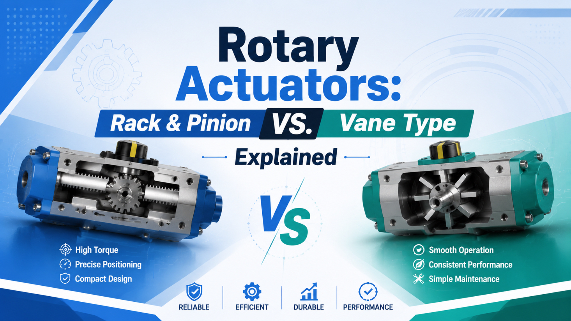
Choose a rack-and-pinion rotary actuator when the application needs a broad model range, substantial external-load capacity, adjustable stops, or higher torque options. Choose a vane actuator when a compact body and direct limited-angle motion fit the load. SMC offers 90°, 180°, 190°, and 270° configurations across the two mechanisms (SMC USA, 2026).
There isn’t a universal winner. A mechanism name doesn’t tell you the usable torque, stopping energy, repeatability, or shaft-load capacity. Those values belong to a particular series and size at a stated pressure. Start with the load and motion profile, then compare catalog data at the plant’s lowest expected moving pressure.
In our experience, wrong selections usually begin with missing load geometry or an optimistic pressure value, not with the choice of mechanism itself.
Key Takeaways
- SMC lists 90°, 180°, 190°, and 270° rotary options, so required angle alone rarely identifies the mechanism.
- Compare usable torque, load inertia, allowed kinetic energy, shaft loads, and stop design at the same pressure.
- Rack-and-pinion offers breadth; vane rewards compact, well-supported loads.
How Do Rack-and-Pinion and Vane Actuators Produce Rotation?
Rack-and-pinion units turn a gear with one or more air-driven racks, while vane units apply pressure directly to a shaft-mounted vane. Parker’s pneumatic catalog separates both families and lists model-dependent rotations below 95° and above 100° for each, confirming that mechanism and travel angle are separate choices (Parker, 2025).
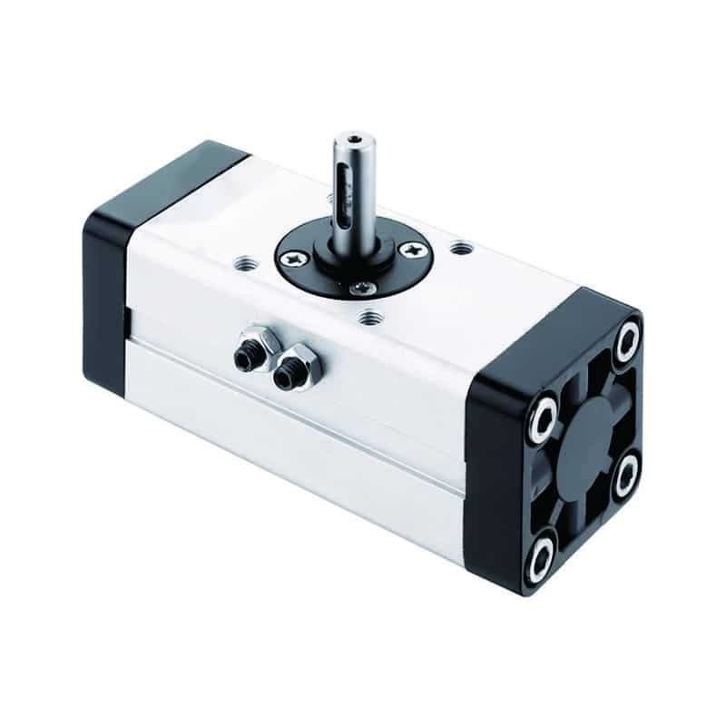
A rack-and-pinion rotary actuator is a limited-angle drive that uses an air-driven rack to turn a pinion and output shaft. A dual-rack arrangement can balance forces around the pinion and increase torque within a compact housing, but the exact construction varies by series.
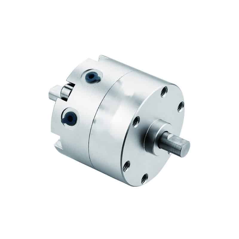
A vane rotary actuator is a direct-drive unit in which pressure acts on a sealed vane connected to the rotor. Single-vane and double-vane versions aren’t interchangeable. SMC says a double-vane option can provide approximately twice the torque with similar outside dimensions, but standardized angles may be limited to 90° or 100° (SMC Europe, 2026).
If the shaft must rotate continuously, neither mechanism may be the right category. Review the difference between a pneumatic motor and a limited-angle rotary actuator before specifying a 360° requirement.
Rack & Pinion vs. Vane: What Does the Catalog Really Support?
At 100 psi, Parker’s pneumatic catalog lists vane families from 1.33 to 2,355 lb-in and rack-and-pinion families from 39 to 10,000 lb-in. Parker also warns that these figures are only a guide because pressure rating, rotation, options, and actual output vary by product (Parker, 2025).
That catalog spread supports a useful conclusion: rack-and-pinion has broader high-output coverage in this product line, but vane isn’t automatically a low-torque technology. Comparing the largest rack model with a small vane model proves nothing about two candidates sized for the same machine.
| Selection factor | Rack-and-pinion tendency | Vane tendency | What must be checked |
|---|---|---|---|
| Motion generation | Piston and rack turn a pinion | Pressure acts directly on a vane | Porting, direction, and return method |
| Product range | Broad size, torque, and stop options | Compact limited-angle packages | Specific series, size, and angle |
| Backlash | Gear mesh can introduce clearance | No rack-and-pinion gear mesh | Published backlash or repeatability value |
| External loads | Many series offer supported shafts or tables | Capacity varies sharply by construction | Axial, radial, and moment ratings |
| End-of-rotation control | Cushions, bumpers, or shock options are common | Internal or external stops depend on series | Allowed kinetic energy and stop torque |
| Installation envelope | Often longer or wider around piston bores | Often compact around the output shaft | Full CAD envelope, fittings, and sensors |
The defensible comparison is candidate against candidate. Put both model codes in one worksheet and normalize pressure, rotation angle, duty cycle, output interface, and load support. If a row can’t be filled from a datasheet, it is an RFQ question, not a reason to assume one mechanism wins.
How Should Torque and Stopping Energy Be Compared?
Parker shows pneumatic rotary actuator output reaching 10,000 lb-in at 100 psi in its range chart, yet explicitly directs engineers to the actual product data before specifying a unit. Usable torque must exceed load, friction, and acceleration demand at the lowest moving pressure, not merely match a catalog headline (Parker, 2025).
Start by separating the torque components:
For a horizontal indexing arm, acceleration torque is linked to rotational inertia and angular acceleration:
An appropriate design margin comes after those terms are estimated. Don’t hide unknown friction, a poorly defined payload, or a pressure-drop problem inside a universal 25% or 50% multiplier. If supply pressure falls while the actuator moves, calculate with the lower pressure and confirm the manufacturer’s torque curve there. Torque starts the motion. Allowable kinetic energy is the motion energy the selected actuator and stop arrangement may absorb without exceeding the catalog limit. SMC treats rotation time, kinetic energy, and allowable load as separate checks for both mechanisms (SMC, 2024).
In our experience, a light load on a long arm is the case most likely to pass a static torque check and still damage an end stop.
For fast cycles, verify all of the following:
- moving mass
- target angle and move time
- permitted rotation-time range
- allowable kinetic energy, calculated from the complete rotating assembly at target speed and compared with the selected stop method
- cushion selection
- minimum pressure and flow measured at the actuator inlet while it moves
Trying to slow an impact only with a small flow control can make cycle time unstable. Meter-out control is usually easier to stabilize than meter-in control for pneumatic loads, but the right arrangement still depends on whether the load can drive the actuator. See the practical meter-in versus meter-out guide before finalizing the circuit.
Rotation Angle, Stops, and Feedback
SMC lists 90°, 180°, 190°, and 270° rotary actuator configurations, while Parker’s WR vane series is adjustable from 30° to 205°. These examples show why “vane stops at 270°” and “rack-and-pinion always reaches 360°” are poor purchasing rules (SMC USA, 2026; Parker, 2025).
Specify the working angle and adjustment window separately. A machine that needs 180° nominal travel may also need ±5° mechanical adjustment for commissioning. Another application may need fixed 90° stops but tight end-position confirmation. Those aren’t the same actuator requirement. Ask how the actuator reaches the end position. Possible methods include an internal hard stop, elastomer bumper, pneumatic cushion, adjustable external stop, or shock absorber. Then confirm where the stop reaction goes. A stop built into the tooling can protect the actuator, but only if the coupling and machine frame can carry the impact.
Sensors confirm position; they don’t create precision. A reed or solid-state switch usually reports an end zone. It doesn’t prove the shaft is within a fraction of a degree under load. For closer angular control, specify the permitted error at the load, the direction of approach, external play, and whether an encoder or closed-loop axis is required. The broader rotary actuator working guide explains when a simple two-position actuator becomes a positioning system.
Can the Output Shaft Carry the Machine Load?
SMC’s selection guide shows how sharply allowable load changes with model size: the listed CRA1 rack-and-pinion series ranges from 29.4 N to 980 N for one axial load direction, depending on size. It also advises avoiding direct shaft loading where possible, even when a tabulated load is permitted (SMC, 2024).
This is why torque alone isn’t enough. A rotary actuator can turn the load and still suffer bearing wear, shaft deflection, or inconsistent end position because the tooling applies excessive radial force or overturning moment.
Calculate or obtain four separate values:
- axial load toward the actuator
- axial pull away from the actuator
- radial load on the shaft
- moment caused by load offset
Keep belt tension, gripper mass, hoses, eccentric fixtures, and acceleration forces in the load model. If the external moment is large, support the tooling with an independent bearing, rotary table, or guided structure. This is the rotary equivalent of controlling side loading on a linear actuator: the actuator should create motion, not serve as an unspecified machine bearing.
From our analysis, a compact vane body stops being the smaller solution when it needs a separate support bearing and custom coupling. Compare the installed assembly envelope, not just the body dimensions.
Speed, Accuracy, and Service Life Are Model-Level Results
SMC’s rotary range includes 90° through 270° configurations and both vane and rack-and-pinion designs, but its selection process still requires model-specific rotation time, kinetic energy, and load checks. Therefore, the mechanism alone cannot support universal claims such as “vane is faster” or “rack-and-pinion is more accurate” (SMC, 2024).
Cycle speed depends on valve flow, tubing, exhaust restriction, actuator volume, load inertia, flow-control settings, cushioning, and allowed impact energy. An undersized valve or long narrow tube can become the limiting component, so check the causes of pneumatic pressure drop when measured motion is slower than the catalog test. Accuracy also needs a definition. End-position repeatability, backlash, absolute angular accuracy, and mid-stroke controllability are different properties. Gear clearance can affect a rack-and-pinion unit, while seal friction, shaft deflection, stop compliance, sensor hysteresis, and external coupling play can affect either design. Service life can’t be assigned as “15 to 20 years” by mechanism either. Cycles, pressure, lubrication policy, air quality, temperature, seal material, side load, stop impact, and maintenance determine wear. Ask for rated life or test conditions for the exact configuration, then compare those conditions with the real duty cycle.
Selection Matrix: Which Mechanism Fits the Application?
Parker’s pneumatic range chart covers both vane and rack-and-pinion models on each side of 100° rotation, and SMC offers both mechanisms across common automation duties. The practical selection rule is to choose the candidate whose verified ratings cover the complete load case, not the one associated with a familiar industry stereotype (Parker, 2025).
| Application condition | Start with | Why | Validation that can reverse the choice |
|---|---|---|---|
| High inertia or substantial external load | Rack-and-pinion | Broad supported-shaft and rotary-table options | Vane model has adequate load and energy ratings |
| Very tight radial envelope | Vane | Direct-drive construction can be compact | External support makes installed package larger |
| Adjustable mechanical end positions | Rack-and-pinion | Common in many series | Selected vane series includes suitable adjustment |
| Simple light-load 90° flip | Vane | Compact motion with few conversion parts | Rack model integrates better mounting or stops |
| Several turns or continuous rotation | Neither by default | Limited-angle actuators may not meet travel | Special multi-turn rack unit or air motor is verified |
| Quarter-turn process valve | Either, plus process-specific review | Both mechanisms can operate 90° valves | Required torque curve, fail action, and interface decide |
Valve automation adds another interface layer. ISO 5211:2026 specifies flange dimensions, drive-component dimensions, and reference interface torques for part-turn actuator attachments (ISO, 2026). It doesn’t size the actuator for the valve or prove the assembly is suitable for the process. For a valve package, obtain break-to-open, run, end-to-close, and unseat torque across the operating differential pressure and temperature range. Also define double-acting or spring-return action, fail position, cycle frequency, corrosion environment, manual override, position indication, and the exact ISO 5211 flange and drive details.
The best mechanism can change after the failure mode is specified. A compact double-acting vane unit may fit the normal motion, while a spring-return rack-and-pinion process actuator may fit the required loss-of-air response. Fail action is a primary requirement, not an accessory choice.
What Goes Into a Build-Ready RFQ?
ISO 5211:2026 covers three interface elements for part-turn valves: flange dimensions, driving-component dimensions, and reference torque values. A useful rotary-actuator RFQ must go further by defining the motion, dynamic load, air conditions, stop strategy, feedback, environment, and required failure behavior (ISO, 2026).
Send the supplier this information:
- mechanism preference
- working angle and direction
- load torque, friction torque, inertia, payload mass, tooling mass, and center-of-mass radius, with the drawing or calculation used to obtain them
- target move time, dwell time, cycles per minute, and annual cycles
- minimum pressure while moving, not only static supply pressure, plus maximum pressure and available valve flow
- shaft loads
- required stop, cushion, bumper, or shock-absorber arrangement
- shaft, key, flange, rotary-table, or ISO 5211 interface details
- feedback method
- ambient temperature, contaminants, washdown, corrosion, and air-quality conditions
- double-acting, spring-return, fail-open, fail-closed, or fail-in-place behavior
Attach the moving assembly drawing when possible. It resolves lever radius, coupling, load offset, interference, and port-access questions faster than a text description. For a replacement, include the full old model code, nameplate pressure, shaft drawing, mounting pattern, port positions, sensor type, and measured cycle behavior.
Jack Chen’s credentials are carried by the page author system. Publisher scope is described on About Us, and readers can submit fact-check corrections or model-specific application data through Contact.
FAQs About Rotary Actuators
SMC offers both vane and rack-and-pinion rotary actuators in common angles from 90° to 270°, so the most frequent questions can’t be answered from mechanism alone. Each answer below identifies the rating or interface that should be verified on the exact candidate datasheet (SMC USA, 2026).
Is rack-and-pinion always stronger than a vane actuator?
No. Parker’s 100 psi range chart reaches 10,000 lb-in for rack-and-pinion and 2,355 lb-in for vane families, showing broader high-torque rack coverage in that catalog, not a universal law. Compare two correctly sized models at the same pressure, angle, duty cycle, and stopping-energy requirement.
Is a vane actuator always faster and more accurate?
No. Rotation time depends on valve flow, tubing, actuator volume, inertia, exhaust restriction, and cushioning. Accuracy must also be defined as backlash, end-position repeatability, or absolute angle. Use the manufacturer’s stated rotation-time range and repeatability or backlash specification for the chosen model instead of assigning performance by mechanism.
Can a vane actuator rotate more than 180 degrees?
Yes. SMC lists rotary configurations up to 270°, and Parker lists PRN vane versions at 270° and 280°. Double-vane versions may trade angle for torque, so specify both values together. If the motion requires continuous rotation, compare an air motor or servo axis rather than assuming any limited-angle actuator will work.
How much torque margin should I use?
There is no universal margin. First calculate load, friction, and acceleration torque, then compare the result with actuator output at the lowest moving pressure. Add a documented design factor for uncertainty and service severity. A percentage can’t compensate for unknown inertia, side load, or end-stop energy.
Does ISO 5211 mean a valve actuator is correctly sized?
No. ISO 5211:2026 standardizes part-turn attachment dimensions and reference interface torques. It doesn’t provide the operating torque of the valve or validate the actuator’s fail action. Check the valve torque curve, process differential pressure, safety factor, coupling strength, flange, drive geometry, and loss-of-air behavior as one assembly.
Sources
-
Parker Pneumatic Actuator Products, Catalog 0900P, product ranges, 100 psi torque, rotation groups, and selection warning. Retrieved 2026-07-15.
-
Parker Pneumatic Rotary Actuator Overview, series torque and angle summaries. Retrieved 2026-07-15.
-
SMC Rotary Actuators Model Selection, rotation time, kinetic energy, shaft loads, and selection checks. Retrieved 2026-07-15.
-
SMC USA Rotary Actuators, mechanism overview and 90° to 270° configurations. Retrieved 2026-07-15.
-
SMC Europe Rotary Actuators, series-dependent characteristics and double-vane notes. Retrieved 2026-07-15.
-
ISO 5211:2026, part-turn actuator attachment dimensions and reference interface torques. Retrieved 2026-07-15.
-
SMC Corporation video: MSQ Series Rotary Table, rack-and-pinion rotary-table demonstration. Retrieved 2026-07-15.