

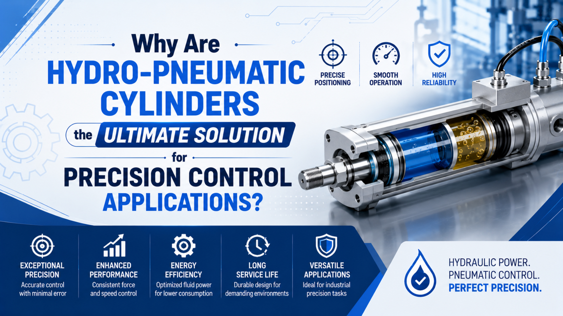
Hydro-pneumatic cylinders are not the ultimate solution for every precision-control application. They are strong candidates when the real requirement is smooth low-speed feed, a controlled approach, or a short high-force working stroke and the plant already has suitable compressed air. They are weaker candidates when the machine needs many programmable positions, continuous hydraulic power, or a simple two-position move that a standard pneumatic cylinder can perform.
The phrase hydro-pneumatic cylinder is also broader than it sounds. It can describe an air-hydro circuit that converts air pressure to approximately equal oil pressure, a hydraulic resistance unit mechanically linked to a pneumatic actuator, or an intensifier drive that creates a much higher oil pressure for a power stroke. Those architectures solve different problems.
Key Takeaways
- SMC recommends an air-hydro cylinder load ratio of 50% or less for its CC selection method.
- Equal-pressure air-hydro control improves feed behavior but does not multiply force.
- An intensifier can create a short high-force stroke, while programmable positioning normally needs feedback and a controller.
An air-hydro system earns its place only when the requirement is measurable. Replace “smooth,” “precise,” and “high force” with a speed band, position window, work force, stroke zone, payload, cycle rate, and safe state. Then select the architecture.
What Does a Hydro-Pneumatic Cylinder Actually Control?
SMC’s CC selection procedure defines load ratio as load divided by theoretical output and keeps it at 50% or less while selecting the valve unit from the required speed function (SMC CC Air-hydro Unit catalog). A hydro-pneumatic cylinder therefore controls one declared variable—usually feed speed, hydraulic resistance, or a high-force power stroke—not universal precision.
A hydro-pneumatic cylinder is a fluid-power actuator or actuator circuit that uses compressed air as the primary energy input and hydraulic oil for controlled transmission, resistance, or pressure intensification. What it controls depends on the arrangement:
| Required result | Useful hydro-pneumatic function | What it does not prove |
|---|---|---|
| Smooth low-speed feed | Meter oil through a throttle or pressure-compensated flow valve | Absolute position accuracy |
| Controlled approach | Switch between fast travel and a slower feed zone | Collision-free motion without sensing |
| Short high-force work stroke | Intensify air pressure into higher oil pressure | High force across every millimeter of total stroke |
| Reduced end impact | Shape deceleration or resist motion hydraulically | Safe load holding after energy loss |
| Intermediate stop | Close a stop valve under defined conditions | Servo positioning at many recipe-driven targets |
The distinction matters because speed control, position control, and force control are different engineering tasks. A hydraulic flow restriction can make low-speed travel steadier. It does not tell the controller where the rod is. An intensifier can raise work pressure. It does not automatically regulate press force at the tooling.
NIST treats position accuracy and repeatability as separate metrology quantities and emphasizes measurement uncertainty when certifying linear motion performance (NIST linear motion metrology). For a production machine, the acceptance result should therefore be measured at the part, fixture, or tool datum—not inferred from the actuator label.
That source boundary matters. SMC describes its CC unit as converting air pressure to equivalent hydraulic pressure. The description supports smoother oil-metered motion, but it does not support a general claim that every air-hydro unit multiplies force or reaches a fixed positioning tolerance.
For a broader comparison of accuracy, repeatability, resolution, and process tolerance, see the guide to cylinder and electric-actuator precision.
Three Hydro-Pneumatic Architectures to Separate
Three distinct architectures appear in the primary product documentation: SMC’s equivalent-pressure CC air-hydro unit, Parker’s oil-metering Par-Check, and TOX’s intensifier-based Powerpackage (SMC; Parker; TOX). Separating them reveals whether the machine needs steady velocity, one checked feed zone, or pressure multiplication for a short work stroke.
1. Air-Hydro Unit for Smooth Feed
An air-hydro unit uses compressed air to act on a converter, producing approximately equivalent hydraulic pressure. Oil then moves the compatible air-hydro cylinder, while the valve unit meters oil flow. Because liquid is far less compressible than air, the circuit can reduce jumping at startup and improve low-speed consistency.
This is the architecture to consider for controlled transfer, cutting feed, drilling feed, or another motion where velocity stability matters more than programmable position. Depending on the valve arrangement, the machine may have fast-forward, slow-feed, skip, or stop functions.
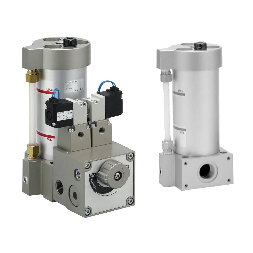
The pictured hardware is an air-hydro converter and valve unit, not a standalone cylinder. Its oil level, valve function, hydraulic piping, and compatible actuator are part of the motion system.
2. Hydraulic Resistance Unit for a Controlled Feed Zone
Parker’s Par-Check is a mechanically linked hydraulic resistance unit. As its rod moves, the piston forces oil through an adjustable needle or speed-control valve. The linked pneumatic or mechanical actuator supplies the motion; the hydraulic unit resists and shapes it.
This arrangement is useful when only a defined portion or direction of motion needs controlled feed. The linkage, guide, available checking stroke, oil level, load direction, and alignment all matter. It is not a pressure intensifier, and its checking-load rating is not the same as actuator output force.
3. Intensifier Drive for a High-Force Power Stroke
A pneumohydraulic intensifier uses a large air-driven piston and a smaller hydraulic plunger to create higher oil pressure. A typical pressing sequence has fast approach, contact detection or resistance, a short power stroke, and return. TOX documents the intensifier piston, plunger, high-pressure chamber, working piston, and power-stroke valve as separate functional elements.
This architecture fits pressing, clinching, riveting, embossing, forming, or assembly work that needs substantial force only near contact. It is not automatically the best option for a long force stroke or continuous high-power duty. A conventional hydraulic power unit may be easier to cool, monitor, and maintain when high hydraulic power is required across much of the cycle.
Engineering insight: The quickest architecture test is to divide the stroke into zones. If the entire move needs only steady speed, start with an air-hydro feed circuit. If only the final few millimeters need high force, investigate an intensifier. If every point must be programmable, treat the application as a motion-control axis rather than a cylinder-selection problem.
In our application reviews, the most revealing question is often, “Where in the stroke does the process need hydraulic behavior?” A precise answer usually narrows the choice faster than a long list of generic actuator benefits.
Precision Positioning Needs More Than Oil Control
At 50 mm/s, SMC gives an intermediate-stop example of ±0.75 mm for a specified CCVS timing condition, calculated from 50 mm/s multiplied by ±0.015 seconds (SMC CC catalog). Hydro-pneumatic control can improve velocity stability, but this product-specific stop example does not establish universal position accuracy.
A stop valve still has switching delay. Oil and seals still have temperature-dependent behavior. The load, guide, linkage, sensor, controller scan, valve response, and mechanical compliance still influence where the process stops.
Use four separate acceptance terms:
- Speed stability: variation around the target velocity during the defined feed zone.
- Repeatability: spread of repeated results under the same approach, load, temperature, and pressure.
- Accuracy: difference between the measured result and the reference target.
- Settling behavior: overshoot, bounce, drift, or vibration after the command changes.
An end-stop application may repeat well because a rigid stop defines the final location. A slow-feed drilling or cutting application may care more about velocity variation than final position. A press may care about force-displacement data. Those are three different acceptance tests.
For programmable intermediate positions, the normal architecture includes a position sensor, controller, suitable proportional directional valve, guided mechanics, and fault logic. The guide to proportional valves for precision motion explains that closed-loop boundary in more detail.
A timed stop example cannot be promoted into a universal positioning specification. Record speed, approach direction, load, oil temperature, supply pressure, valve state, sensor datum, dwell, and cycle count whenever position or repeatability is part of the purchase requirement.
Sizing an Air-Hydro or Intensifier System
SMC recommends converter capacity at least 1.5 times cylinder displacement as a guide when the stroke exceeds its capacity chart, and it limits converter oil-level speed to 200 mm/s in that selection method (SMC CC catalog). These checks show why bore and stroke alone are insufficient.
Start With the Load and Stroke Zones
For an equal-pressure air-hydro circuit, theoretical cylinder force still begins with pressure differential and effective piston area:
Here, is theoretical actuator force in newtons, is effective pressure differential across the piston in pascals, and is effective piston area in square meters. The approximation excludes seal friction, back pressure, acceleration, line loss, and mechanical losses. Because the converter produces approximately equivalent hydraulic pressure, it should not be treated as an intensifier.
The oil displacement for one controlled cylinder chamber is approximately:
Here, is displaced oil volume in cubic meters, is the applicable piston or annular area in square meters, and is controlled stroke in meters. Add the manufacturer’s capacity margin and verify converter oil-level speed, valve capacity, piping volume, and orientation.
Calculate Intensifier Pressure Separately
For an idealized intensifier, the approximate oil pressure is:
Here, and are oil and air pressure in the same units, while and are the effective air-piston and hydraulic-plunger areas in the same area units. The area ratio is the ideal intensification ratio. Real output is lower because of friction, pressure loss, valve behavior, seal preload, and dynamic effects.
The corresponding idealized work force is:
Here, is work force in newtons and is the hydraulic working-piston area in square meters. The practical selection consequence is simple: request the manufacturer’s force-versus-stroke data and allowed power-stroke length. Do not extrapolate a short power-stroke rating across the total approach stroke.
The existing pneumatic cylinder force calculator can provide a baseline for a conventional air cylinder, but it does not model an intensifier. For the underlying pressure-area relationship, use the pneumatic cylinder formula guide.
Engineering insight: The most useful sizing sketch is not one full-stroke arrow. Draw fast approach, controlled feed, contact, power stroke, dwell, and return as separate zones. Then mark required force, speed, sensing, and safe state in each zone. This exposes whether hybrid hardware actually removes complexity or merely hides it inside one actuator package.
Best-Fit Applications for Hydro-Pneumatic Cylinders
TOX documents a product family spanning 2 to 2,000 kN of press force, while its standard integrated power strokes are much shorter than total stroke (TOX Powerpackage overview). The range is product-specific, but the staged-motion principle explains the best-fit applications.
| Application pattern | Likely fit | Main acceptance measure |
|---|---|---|
| Fast approach plus slow drilling or cutting feed | Air-hydro unit | feed-speed band under defined load |
| One controlled section of a machine feed | Hydraulic resistance unit | checking load, feed rate, and transition point |
| Clinching, riveting, embossing, pressing, or forming | Intensifier drive | force-displacement curve and power-stroke length |
| Simple clamp, ejector, gate, or two-position transfer | Standard pneumatic cylinder often sufficient | end position, force, and cycle time |
| Many recipe-driven positions or motion profiles | Electric or servo-pneumatic axis | loaded accuracy, repeatability, and settling time |
| Long high-force stroke or sustained hydraulic power | Conventional hydraulic system often stronger | continuous force, heat, flow, and load holding |
The title’s “ultimate solution” is therefore conditional. Hydro-pneumatic hardware is compelling when it concentrates hydraulic behavior exactly where the process needs it. It is harder to justify when every stroke zone needs the same high pressure, when position recipes change frequently, or when a standard speed controller and mechanical stop already meet the requirement.
If the project is still choosing between air and oil power at system level, review the hydraulic-versus-pneumatic comparison. If the main problem is ordinary cylinder speed, start with the meter-in versus meter-out guide before adding a second fluid.
Commissioning and Maintaining the System
SMC warns that a fast-to-slow speed ratio much above approximately 3:1 in one skip-valve arrangement can promote cavitation and air bubbles; it also recommends short, rising hydraulic piping and avoiding downward-facing ports in the cited circuit guidance (SMC CC catalog). Oil routing is therefore part of commissioning, not an afterthought.
Use this sequence:
- Verify the mechanics. Check guidance, alignment, linkage, side load, hard stops, tooling stiffness, and the actual contact point.
- Confirm the fluid paths. Record air pressure during motion, oil type, oil level, hydraulic line inside diameter and length, valve orientation, and exhaust restriction.
- Remove trapped air as instructed. Entrained air reduces stiffness and can reintroduce jump, delay, or unstable stopping.
- Begin at low speed and force. Confirm direction, transition logic, stop-valve state, sensing, and fault behavior before increasing settings.
- Capture one complete cycle. Log command, cylinder position, air pressure, oil pressure where applicable, force, and cycle time on one time base.
- Test the operating envelope. Repeat at minimum and maximum payload, expected temperature range, lowest dynamic supply pressure, and realistic cycle rate.
- Define inspection triggers. Use oil level, leakage, speed drift, force drift, temperature, noise, seal condition, and cycle data—not a generic calendar interval.
For a Par-Check-style unit, Parker’s instructions connect oil-level indication and in-line or properly guided parallel mounting directly to operation. For an air-hydro converter, SMC notes that leakage across sliding seals can shift oil level between sides. For an intensifier, the supplier’s seal, oil reservoir, pressure-valve, and power-stroke inspection instructions govern.
Engineering insight: When speed begins to drift, do not adjust the throttle first. Compare oil temperature, air in the oil, converter level, load, supply pressure, exhaust restriction, linkage friction, and valve command. A throttle adjustment can hide the symptom while moving the system away from its commissioned baseline.
Hydraulic oil adds failure modes that a standard pneumatic cylinder does not have: oil-level migration, aeration, cavitation, temperature-sensitive viscosity, internal leakage, and hydraulic-line restrictions. The smoother motion benefit is real only while those conditions remain controlled.
For general actuator service planning, see the cylinder and actuator maintenance comparison.
RFQ and Safety Review Requirements
ISO 4413 and ISO 4414 were both published in 2010 and cover general rules and safety requirements for hydraulic and pneumatic systems respectively (ISO 4413; ISO 4414). A hydro-pneumatic installation crosses both fluid-power boundaries, so the RFQ must describe stored energy and safe isolation on both sides.
Send suppliers these inputs:
- architecture requested or process result to be solved;
- payload, external force, load direction, and side-load condition;
- total stroke plus fast, feed, contact, power, dwell, and return zones;
- force, speed, position, and settling acceptance bands;
- dynamic air pressure and available flow at the machine;
- cylinder bore, rod diameter, mounting, guide, and orientation;
- oil specification, converter capacity, hydraulic line route, and ambient temperature;
- valves, sensors, PLC signals, transition logic, and diagnostic outputs;
- normal stop, emergency stop, air loss, power loss, blocked-tool, and restart behavior;
- expected cycles, operating hours, maintenance skills, and stocked service parts;
- acceptance test method, instruments, sampling rate, and number of cycles.
Do not assume that closing the air valve removes hydraulic pressure or mechanically supports a load. OSHA 1910.147 applies when unexpected startup or release of stored energy can injure workers and requires an energy-control procedure for covered servicing work (OSHA lockout/tagout). The machine risk assessment may require blocking, restraint, monitored dumping, redundant valves, or another engineered control.
ISO 15552 establishes a 10 bar dimensional series for detachable-mounting pneumatic cylinders with bores from 32 to 320 mm. It does not make every hydro-pneumatic product directly interchangeable with every ISO cylinder (ISO 15552). Confirm mounting datum, body envelope, ports, oil connections, sensors, rod end, stroke, cushioning, transition controls, and safe state model by model.
If the application has distinct feed and power zones, send the completed duty sheet through the engineering contact page. Ask the supplier to mark assumptions on the circuit and force-versus-stroke curve so the quotation can be tested rather than accepted as a generic “precision” promise.
In our experience, a marked-up circuit and force-versus-stroke curve prevent more selection errors than a compatibility statement alone. They expose the transition point, pressure boundary, sensing assumption, and safe state before hardware reaches the machine.
FAQs About Hydro-Pneumatic Cylinders
ISO 15552 covers a 10 bar pneumatic dimensional series, while SMC’s CC air-hydro catalog adds converter, oil-volume, valve, and piping requirements. These five questions clarify why a familiar cylinder envelope does not make the hybrid system a drop-in precision upgrade.
Are hydro-pneumatic cylinders more precise than standard pneumatic cylinders?
They can provide steadier low-speed motion, but that is not the same as higher position accuracy. Final precision depends on the architecture, valve timing, sensing, controller, load, guide, temperature, pressure, and measurement method. Require a loaded acceptance test for the variable the process actually uses.
Does every hydro-pneumatic cylinder increase force?
No. An equal-pressure air-hydro converter mainly changes the controlled medium from air to oil and does not inherently multiply pressure. A pneumohydraulic intensifier can raise oil pressure through an area ratio, but the rated force normally applies to a defined power-stroke range and operating condition.
Can a hydro-pneumatic cylinder directly replace a standard pneumatic cylinder?
Not by assumption. Some cylinders may share mounting dimensions, but the complete system can require a converter, oil reservoir, valve unit, hydraulic piping, different ports, transition controls, and maintenance access. Verify the exact model, circuit, envelope, sensors, force, speed, and safe state before replacement.
What maintenance does an air-hydro system require?
Follow the selected manufacturer’s instructions for oil type, oil level, seals, leakage, trapped air, valve function, hydraulic piping, and inspection intervals. Trend speed, force, temperature, and cycle behavior. A fixed universal 12- or 18-month service interval is not a reliable substitute for equipment-specific guidance.
When should I choose electric or conventional hydraulic motion instead?
Choose an electric or servo-controlled axis when the process needs many programmable positions, traceable motion profiles, or tightly controlled settling. Consider conventional hydraulics when high force or controlled power is required over a long stroke or sustained duty. Use standard pneumatics when simple end-to-end motion already meets the test.
Sources
Nine primary references define the architecture, selection limits, precision terminology, dimensional scope, and safety boundary used in this guide.
- SMC CC Series Air-hydro Unit catalog
- Parker Par-Check operating principles and instructions
- TOX Powerpackage operating manual
- TOX Powerpackage product overview
- NIST: Ultra-Precision Linear Motion Metrology
- ISO 15552:2018 pneumatic cylinder dimensional series
- ISO 4413:2010 hydraulic fluid-power safety requirements
- ISO 4414:2010 pneumatic fluid-power safety requirements
- OSHA 29 CFR 1910.147 control of hazardous energy