

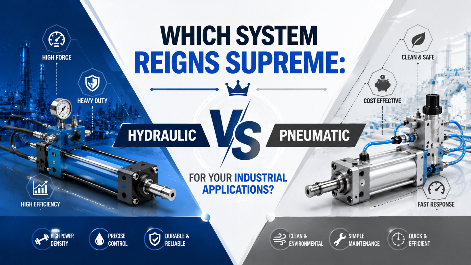
Neither hydraulic nor pneumatic power wins every industrial application. Hydraulics is usually the stronger candidate when high force density, load holding, and controlled motion under heavy load dominate. Pneumatics is often the better fit for fast, repetitive end-to-end motion when plant air already exists and cleanliness, simple hardware, and easy replacement matter.
The reliable way to choose is to freeze one duty, then compare both systems at the same load, stroke, cycle time, environment, safety state, and ownership boundary. A catalog pressure or component price cannot decide the system by itself.
Key Takeaways
- ISO 15552 covers a 10 bar pneumatic cylinder series, while one Parker compact hydraulic series is rated to 207 bar.
- Force still follows
F = pA; pressure alone does not prove that a complete system fits.- Compare energy, maintenance, leakage, controls, and safe isolation across the same machine duty.
A hydraulic system is a power-transmission system that uses pressurized liquid, usually oil. A pneumatic system is a power-transmission system that uses pressurized gas, usually compressed air. The National Fluid Power Association treats both as fluid-power technologies. It also notes that no single power-transmission method is best for every application.
What Should You Compare Before Choosing Hydraulic or Pneumatic Power?
Start with one written duty sheet, not a technology preference. ISO 4413 and ISO 4414 were both published in 2010 and address safety, reliability, maintenance, energy efficiency, and environmental considerations for hydraulic and pneumatic machinery systems respectively (ISO 4413; ISO 4414).
Freeze these inputs before asking suppliers for concepts or quotations:
| Duty input | What to record | Why it changes the decision |
|---|---|---|
| Load | mass, external force, direction, load variation | sets required actuator force and holding method |
| Motion | stroke, target time, acceleration, deceleration | sets flow, valve size, cushioning, heat, and shock |
| Positioning | end-to-end, intermediate stops, repeatability, force control | determines whether simple valves are enough |
| Duty profile | cycles per minute, dwell, shifts, peak simultaneity | separates intermittent demand from continuous power |
| Load state | horizontal, vertical, suspended, over-running | changes stored-energy and load-holding controls |
| Environment | washdown, dust, temperature, fire risk, clean area | changes fluid, seals, enclosure, exhaust, and leak tolerance |
| Utilities | available air pressure and flow, electrical capacity, cooling | determines how much infrastructure already exists |
| Maintenance | available skills, spares, cleanliness practice, response time | affects uptime more than a generic service interval |
| Safety state | air or power loss, emergency stop, maintenance isolation | defines valves, blocking, dumping, and restart behavior |
| Ownership boundary | actuator only, machine package, or plant utility | prevents component cost from masquerading as system cost |
The ownership boundary often changes the answer. A pneumatic axis connected to a healthy plant-air header may require only point-of-use treatment, valves, tubing, and an actuator. The same axis in a facility without compressed air must carry part of the compressor, dryer, receiver, distribution, and monitoring cost. Compare both cases explicitly.
In our experience, the comparison improves as soon as the team writes down what the plant already owns and what the machine project must add. That simple boundary check prevents an inexpensive actuator from being presented as an inexpensive system.
If the project is also considering electric motion, use the broader cylinder and actuator comparison. This guide stays with the hydraulic-versus-pneumatic decision.
Force Density Starts With Pressure and Area
Hydraulics usually provides greater force density because practical hydraulic products operate at much higher pressure. ISO 15552 defines a pneumatic cylinder series rated to 1,000 kPa, or 10 bar. Parker’s U160S compact hydraulic series lists working pressure up to 207 bar for its stated sizes (ISO 15552, 2018; Parker U100S/U160S catalog, accessed 2026).
Force density is the usable actuator force available within a given physical envelope. It is often more useful than comparing force alone because a large pneumatic bore may produce the load but fail the machine-space or air-demand constraint.
Both cylinder types begin with the same pressure-area relationship:
Theoretical extension force = pressure at the cylinder x full piston area
Theoretical retraction force = pressure at the cylinder x (piston area - rod area)
This is only the starting point. The design must allow for pressure drop, back pressure, seal friction, side load, acceleration, gravity, shock, temperature, and a risk-appropriate safety factor. The related guide to pressure differential and pneumatic force explains why regulator pressure is not always the pressure acting across the piston.
Consider one transparent same-bore illustration. A 50 mm piston has an area of approximately 1,963 mm². At 6 bar, its theoretical extension force is about 1.18 kN. Parker’s U160S table lists 40.6 kN for its 50 mm hydraulic cylinder at 207 bar. The ratio is about 34.5 for those two declared pressure points, not a universal hydraulic-to-pneumatic multiplier.
| Same-bore illustration | Pneumatic case | Hydraulic catalog case |
|---|---|---|
| Bore | 50 mm | 50 mm |
| Pressure | 6 bar | 207 bar |
| Piston area | 1,963 mm² | 1,963 mm² |
| Theoretical extension force | 1.18 kN | 40.6 kN |
| Scope | formula illustration | Parker U160S catalog condition |
For a pneumatic candidate, check the bore, rod diameter, working pressure, friction allowance, and safety factor with the Pneumatic Cylinder Force Calculator. A hydraulic candidate must be sized from its own pressure rating, fluid, mounting, rod-loading, speed, and stopping requirements.
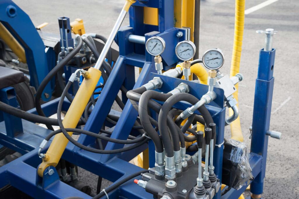
Hydraulic force density becomes decisive when a pneumatic bore would be too large, air consumption would be unreasonable, or the load must be controlled under sustained high force. Pneumatics remains credible when force is moderate and the job is primarily clamping, ejecting, indexing, transferring, or moving between defined end positions.
Which System Is Faster or Easier to Control?
There is no universal speed winner. ISO 6358-1 characterizes pneumatic component flow using sonic conductance and critical pressure ratio, while a hydraulic axis is likewise limited by pump flow, valve capacity, pressure loss, load, and moving volume. Media type alone does not specify stroke time (ISO 6358-1).
Pneumatic motion can be extremely quick for short, repetitive strokes because air can be switched and exhausted with simple directional valves. Real cylinder speed still depends on valve flow, port size, tube inside diameter and length, exhaust restriction, cushion setting, payload, and dynamic pressure at the actuator. Long tubing or an undersized valve can erase the expected advantage.
Hydraulic motion is often selected when the load is heavy and speed must remain controlled throughout the stroke. Proportional and servo-hydraulic systems can regulate pressure, flow, position, and force, but they require suitable sensors, valve bandwidth, filtration, thermal control, and commissioning. A basic hydraulic cylinder is not automatically a precision axis.
| Motion requirement | Pneumatic tendency | Hydraulic tendency |
|---|---|---|
| Fast two-position movement | often simple and effective | possible, but may add unnecessary infrastructure |
| Heavy load at controlled speed | large bore and high flow may become impractical | strong candidate because of force density |
| Many programmable positions | requires proportional or servo-pneumatic control | requires proportional or servo-hydraulic control |
| Compliant contact | air compressibility can help, but complicates position control | fluid stiffness supports controlled force, subject to circuit design |
| Long dwell under load | pressure must be maintained and leakage managed | load-holding valves and leakage behavior must be engineered |
Don’t use “instantaneous response” or “excellent precision” as technology labels. Define target stroke time, settling time, repeatability, allowable overshoot, and behavior after power or pressure loss. For pneumatic circuits, the cylinder flow and timing formulas provide the next sizing step.
Energy Depends on the Complete System Boundary
Pneumatic energy must be measured at the compressor, not only at the actuator. The U.S. Department of Energy reports that more than 80% of compressor input energy can be lost as heat. Demand reduction, pressure control, storage, leak repair, and compressor specific power therefore belong in the comparison (DOE Better Plants, accessed 2026).
That fact does not prove that every hydraulic machine uses less energy. A hydraulic power unit that idles at pressure, throttles large flows, or rejects heat continuously can waste substantial power. Variable-displacement pumps, accumulators, unloading circuits, and demand-controlled operation can change the result. The actual duty profile matters.
Compare annual energy with measured or supplier-supported inputs:
Pneumatic annual energy = average free-air demand x compressor specific power x annual operating hours

Hydraulic annual energy = measured or predicted electrical input across run, hold, idle, and cooling states x annual operating hours
Use the same time boundary. If a pneumatic axis cycles for 12 seconds and waits for 48 seconds, its demand has a 20% active duty ratio, but compressor unload power and plant leaks may continue during the wait. For hydraulics, include pump standby and cooling power during the same 60-second window.
The Compressed Air Energy Cost Calculator can estimate the pneumatic side from average flow, duty cycle, annual hours, specific power, and electricity price. Use measured compressor data where possible. A nominal motor rating is not the same as actual system input.
If pressure at the machine falls during simultaneous demand, review the pneumatic pressure-drop troubleshooting method before increasing the regulator setting. Raising header pressure to fix one restricted branch can increase plant-wide energy use.
How Do Installation and Maintenance Costs Compare?
Component prices are not total ownership cost. AutomationDirect’s hydraulic overview identifies at least six support elements around the actuator: reservoir, pump, filtration, valves, hoses, and often a heat exchanger. A pneumatic machine needs air preparation, valves, tubing, exhaust treatment, and a share of the plant-air infrastructure (AutomationDirect).
Build the comparison around the actual site:
| Cost boundary | Pneumatic questions | Hydraulic questions |
|---|---|---|
| Initial hardware | Is plant air already available at the required dynamic pressure and flow? | Is a new power unit, reservoir, filtration, and cooling package required? |
| Installation | What tube sizes, drops, FRL, isolation, exhaust, and drainage are needed? | What pipe or hose ratings, return lines, guarding, spill controls, and commissioning are needed? |
| Energy | What is average free-air demand and compressor specific power? | What are run, hold, idle, and cooler electrical inputs? |
| Maintenance | Who drains, filters, checks leaks, and replaces seals? | Who samples fluid, controls contamination, services filters, and inspects hoses? |
| Downtime | Are valves, cylinders, fittings, and seals locally stocked? | Are pumps, valves, seals, hoses, and clean service procedures available? |
| End of life | Can components be exchanged without redesigning the circuit? | How will fluid be drained, contained, and disposed of? |
Avoid fixed claims such as “pneumatic maintenance every three months” or “hydraulic fluid changes annually.” Inspection and service intervals belong to the selected equipment, fluid condition, environment, operating hours, failure consequences, and manufacturer instructions.
Maintenance competence is a design input. Pneumatic faults are often traced through leaks, contamination, pressure drop, valve flow, exhaust restriction, and worn seals. Hydraulic faults add fluid cleanliness, temperature, aeration, cavitation, hose condition, internal leakage, and pump or valve diagnostics.
In our experience, a theoretically superior system becomes the wrong choice when the site cannot keep its fluid clean, diagnose its controls, or obtain critical spares. The existing maintenance comparison for cylinders and actuators provides a useful service-planning companion.
Is Pneumatic Safer and Cleaner Than Hydraulic?
Neither system is inherently safe. OSHA 1910.147 explicitly lists hydraulic and pneumatic energy and requires hazardous stored or residual energy to be relieved, disconnected, restrained, or otherwise rendered safe before covered servicing. ISO 4413 and ISO 4414 provide the corresponding system-level safety frameworks (OSHA 1910.147).
Hydraulic leakage can create slip, fire, contamination, and loss-of-load-control risks. A fine high-pressure jet can also penetrate skin. The UK Health and Safety Executive reports serious hydraulic injection injuries above 100 bar and warns that injury may occur at much lower pressure. Never search for a suspected pinhole leak with a hand (HSE, 2014).
Pneumatic leakage normally avoids an oil spill, which can be valuable around packaging, electronics, food equipment, and clean production. It is not harmless. A failed or disconnected air hose can whip; exhaust can propel debris; compressed-air noise can damage hearing; and trapped air can move an actuator after the supply has been closed. OSHA specifically addresses hose-whip hazards from accidental pneumatic-tool disconnection (OSHA interpretation).
| Hazard | Pneumatic control | Hydraulic control |
|---|---|---|
| Unexpected motion | lockable isolation, verified dump, controlled restart, mechanical restraint where needed | lockable isolation, pressure release, blocking, load-holding valves, controlled restart |
| Hose or line failure | rated tube and hose, secure fittings, guarding, excess-flow protection where applicable | rated hose and fittings, routing, guarding, inspection, burst protection where required |
| Stored energy | discharge receivers and trapped volumes; verify zero-energy state | discharge accumulators and trapped pressure; mechanically support raised loads |
| Leakage | detect and repair air leaks; control noise and debris | locate without hand contact; contain fluid and correct contamination source |
| Maintenance access | prevent actuator movement after exhaust or pressure recovery | prevent drift or descent after pressure loss and component leakage |
For pneumatic machinery, integrating a safety exhaust valve is only one part of the safety function. The risk assessment must also cover gravity, springs, external loads, trapped downstream pressure, valve state, restart, and proof testing.
Where Does Each Technology Fit Best?
Industry use reflects different strengths. NFPA identifies off-highway equipment as a major hydraulic application and factory automation as the largest sector for pneumatics. That is a useful pattern, but the machine duty still outranks the industry label when selecting an actuator system (NFPA).
Hydraulic systems are usually the stronger candidate when
- high force must fit into a compact actuator envelope;
- the load is heavy, over-running, or must be held with engineered load controls;
- controlled pressure or force is required across a demanding motion profile;
- the machine already has a suitable hydraulic power unit and maintenance program;
- heat, filtration, leakage containment, and fluid compatibility can be managed.
Pneumatic systems are usually the stronger candidate when
- the motion is repetitive and mainly between defined end positions;
- required force is moderate and an acceptable bore fits the machine;
- fast cycling and simple valve control matter more than multi-position accuracy;
- plant air is available at verified dynamic pressure and flow;
- oil-free operation at the point of use reduces contamination consequences;
- component replacement and circuit simplicity are important.
Stop and reconsider when
- the pneumatic concept needs a very large bore, extreme air flow, or sustained throttling just to imitate hydraulic force;
- the hydraulic concept adds a complete power unit for one light, intermittent two-position movement;
- either concept depends on catalog pressure that is not available at the actuator during motion;
- the safety concept assumes that closing one valve removes all stored energy;
- the quotation omits the utility, cooling, filtration, exhaust, guarding, and maintenance boundary.
A hybrid can be useful when one motion has two distinct phases. Air-over-oil circuits can add steadier speed control to pneumatic motion, and hydro-pneumatic intensifiers can provide a short high-force working stroke after a fast approach. They also combine two media, two maintenance regimes, and more failure modes. Use them only when the staged requirement is explicit.
What Should Go Into the RFQ?
A useful hydraulic-versus-pneumatic RFQ needs at least 10 engineering inputs: load, stroke, orientation, cycle time, duty profile, positioning requirement, available utilities, environment, safety state, and maintenance boundary. Without them, suppliers can quote different assumptions. The resulting prices may look comparable even though the proposed systems solve different duties.
In our experience, the fastest way to expose a weak comparison is to ask each supplier for the pressure and flow available at the actuator during the most demanding motion. Static utility pressure and installed motor power are not acceptance measurements.
Send the following package:
- Load magnitude, direction, variation, and center of gravity.
- Stroke, mounting envelope, rod or carriage load path, and available guidance.
- Target extend and retract times, dwell, cycles per minute, and simultaneous movements.
- Required end positions, repeatability, force control, and allowable shock.
- Dynamic plant-air pressure and flow, or available electrical and hydraulic utility data.
- Temperature, dust, washdown, corrosion, fire, food, or clean-area requirements.
- Normal stop, emergency stop, air loss, power loss, and restart behavior.
- Vertical or suspended-load controls and the required safe maintenance position.
- Expected operating hours, energy price, maintenance skills, and stocked spares.
- Acceptance measurements for force, time, pressure, temperature, leakage, noise, and energy.
Ask each supplier to state exclusions. One quotation may include a hydraulic power unit and cooler, while another assumes they already exist. A pneumatic quotation may omit the compressor and dryer because they are plant utilities. Those exclusions belong beside the price, not in a later clarification.
If both concepts remain viable, send the completed duty sheet and both system boundaries through the engineering contact page. Ask for the assumptions to be marked directly on the quotation so force, cycle time, utilities, safety hardware, and acceptance tests can be reviewed side by side.
FAQs About Hydraulic vs Pneumatic Systems
These five questions cover the decisions most likely to distort a comparison: high-force substitution, speed, energy, environmental impact, and hybrid actuation. Each answer uses the same rule as the main guide: declare the duty and system boundary before drawing a conclusion.
Can pneumatic systems replace hydraulics in high-force applications?
Sometimes, but not because of a universal force threshold. Calculate force from pressure and effective area, then check bore size, air demand, structure, speed, duty, and safety. If the pneumatic package becomes physically large or consumes excessive air, a hydraulic cylinder or a clearly justified intensifier is usually the more practical direction.
Are hydraulic systems always slower than pneumatic systems?
No. Stroke time depends on actuator volume, pump or air flow, valve capacity, lines, load, pressure loss, and the motion profile. Pneumatics often suits fast short strokes, while hydraulics can move heavy loads at controlled speed. Compare a specified cycle instead of assigning one speed label to either technology.
Which system is more energy efficient?
There is no useful answer without a boundary and duty profile. Measure pneumatic energy at the compressor using free-air demand and specific power. Measure hydraulic electrical input during run, hold, idle, and cooling states. Compare both over the same operating window and include leakage, standby power, pressure settings, and controls.
Is compressed air environmentally harmless?
No. An air leak may avoid an oil spill, but producing compressed air consumes electricity, and leakage wastes that energy. Pneumatic exhaust can also create noise and propel particles. Hydraulic leakage has different consequences, including contamination, slip hazards, fire risk, and possible high-pressure injection injury. The risk profiles differ; neither is zero.
When should I consider a hydro-pneumatic solution?
Consider it when the process genuinely needs a fast low-force approach followed by a short, controlled high-force working stroke, or when smoother feed control is required without a full hydraulic axis. Specify the transition, force, stroke, fluid separation, maintenance method, fault state, and energy use before accepting the extra complexity.
Sources
- National Fluid Power Association: What Is Fluid Power?
- ISO 4413:2010, hydraulic fluid power safety requirements
- ISO 4414:2010, pneumatic fluid power safety requirements
- ISO 15552:2018, 10 bar pneumatic cylinder dimensional series
- ISO 6358-1:2013, pneumatic flow-rate characteristics
- Parker U100S and U160S compact hydraulic cylinder catalog
- U.S. Department of Energy: Compressed Air Systems
- OSHA 29 CFR 1910.147, control of hazardous energy
- HSE: Hydraulic injection injury
- AutomationDirect: What Is a Hydraulic System?