

Selecting Class 100 cleanroom pneumatic components starts with the contamination limit at the work zone, then works backward through every possible release path. FDA aseptic-processing guidance associates Class 100, or ISO 5, with no more than 3,520 particles of 0.5 µm and larger per cubic metre in the critical area (FDA Aseptic Processing Guidance, 2004). That room classification doesn’t certify a cylinder, valve, fitting, tube, silencer, or lubricant. The defensible selection is the assembly that meets a documented particle or chemical limit in its real position, while still delivering the required force, speed, repeatability, service life, and cleanability. A material label alone can’t prove that.
Key Takeaways
- Class 100 is commonly aligned with ISO 5, including a 3,520 particles/m³ limit at 0.5 µm and larger in FDA aseptic guidance.
- Evaluate particle, chemical, compressed-air, surface, and viable contamination separately.
- Select with model-specific test conditions, not generic “cleanroom ready” labels.
- Preserve performance margins and qualify the installed assembly.
This guide covers the complete pneumatic chain. For the narrower question of whether non-lubricated construction proves cleanroom suitability, see The Non-Lube Cylinder Advantage in Cleanroom Environments.
What Does Class 100 Actually Require from a Pneumatic Component?
ISO 14644-1 classifies airborne particle concentrations using threshold sizes from 0.1 µm to 5 µm; it doesn’t classify the chemical, viable, or physical nature of those particles (ISO 14644-1, 2015). A component therefore needs a stated test boundary, not a standalone “ISO compliant” label.
Cleanroom suitability is the documented ability of a defined component or assembly to meet a stated cleanliness limit under named operating and sampling conditions. It doesn’t follow automatically from a room class, material, or product-family label. Class 100 comes from the withdrawn U.S. Federal Standard 209E terminology. It remains common in pharmaceutical and semiconductor specifications, but the current room-class language is usually ISO 5. FDA guidance explicitly uses “Class 100 (ISO 5)” for aseptic critical areas (FDA Aseptic Processing Guidance, 2004). That equivalence describes airborne particle concentration, not universal sterility or material rules. Semiconductor processes may be sensitive to airborne molecular contamination, ionic residues, silicone, copper, or trace outgassing. Aseptic filling adds microbial, endotoxin, cleaning, disinfection, and product-exposure risks. Medical-device assembly can sit between those cases. A universal “Class 100” cylinder hides these different acceptance criteria.
Write the application boundary before comparing products:
| Boundary item | What the specification should state |
|---|---|
| Location | Above, beside, or below exposed product; distance from the critical zone |
| Operating state | At rest, normal motion, startup, maximum speed, and maintenance condition |
| Particle requirement | ISO class, particle size, sampling position, background level, and allowable result |
| Chemical requirement | Target substances, concentration limit, material restrictions, and test method |
| Viable requirement | Whether compressed gas, surfaces, or equipment can contact sterile product or a critical zone |
| Cleaning requirement | Agents, concentration, temperature, contact time, frequency, and sterilization method if applicable |
| Performance requirement | Force, stroke, speed, acceleration, side load, moment, cycle rate, pressure, and life target |
The cleanroom class is only one budget. A useful component specification separates at least four budgets: airborne particles, airborne chemicals, compressed-air contaminants, and surface or viable contamination. Passing one budget doesn’t close the others. In our experience, writing these four limits separately exposes vague supplier claims before they reach a qualification protocol. Sector rules stay in place.
Which Contamination Pathways Should You Check Before Choosing Materials?
ISO 14644-14:2026 assesses equipment against airborne particle sizes from 0.1 µm to 5 µm and above, yet its scope explicitly excludes biocontamination, cleanability, decontamination methods, equipment design, and material selection (ISO 14644-14, 2026). Those exclusions define the extra checks a pneumatic specification must add.
Start with the release path, not a preferred alloy. Even a 316L fitting can carry unsuitable thread sealant, trap cleaning residue, leak, or release contamination from a connected polymer tube. An anodized aluminium actuator may be acceptable when it sits below a protected workpiece and has model-specific particle data. Position changes the risk. For example, moving the same valve from below an enclosed workpiece to a position above exposed product can change the acceptable exhaust route, surface finish, cleaning method, and evidence requirement without changing the valve itself.
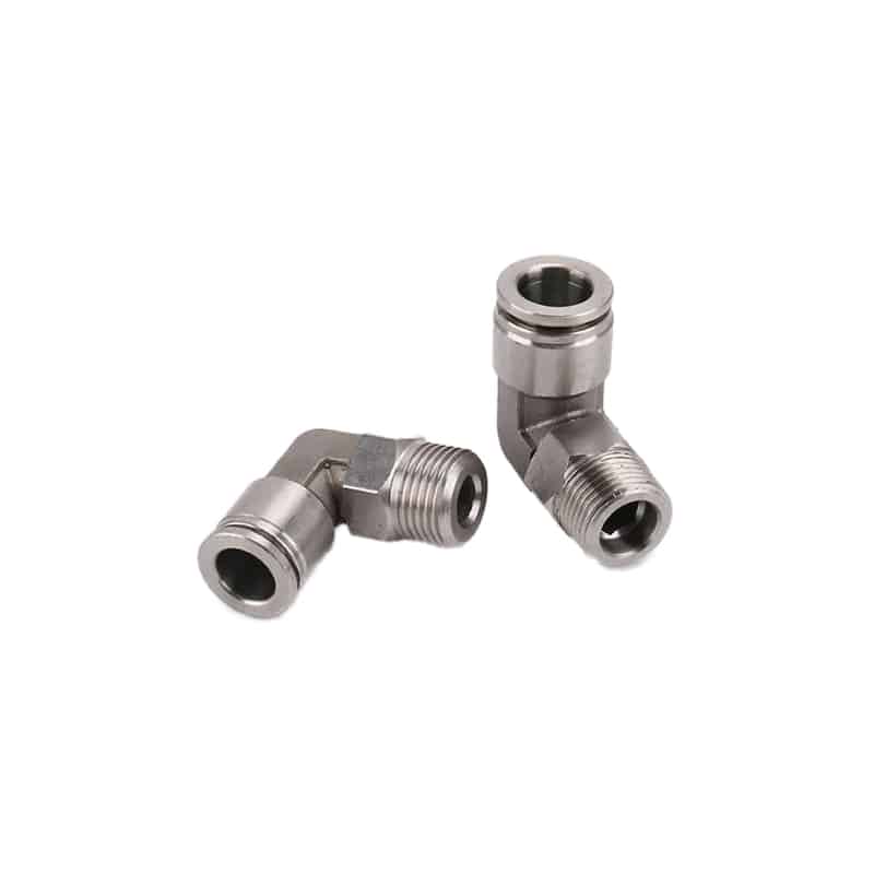
Stainless steel construction can support corrosion resistance and cleanability, but appearance alone doesn’t establish particle, outgassing, seal, or cleaning compatibility.
Use this pathway review:
-
Moving-contact particles. Rod seals, wipers, bearings, guides, bumpers, cushioning parts, and misaligned loads can generate wear debris. Review speed, side load, impact, lubrication, maintenance state, and test duration.
-
Exhaust and leakage. Valve exhaust can disturb protected airflow or release oil, water, particles, silencer fibres, or internal lubricant close to the product. Decide whether to use remote exhaust or a qualified point-of-use filter.
-
Airborne chemicals and outgassing. Grease, adhesives, elastomers, tubing, cable jackets, coatings, and cleaning residues can release compounds without creating countable particles. ISO 14644-15:2026 addresses equipment and material suitability by airborne chemical concentration, but it doesn’t cover cleanability, biocontamination, or process-specific material requirements (ISO 14644-15, 2026).
-
Surface transfer. Exposed threads, recesses, labels, rough finishes, damaged coatings, and inaccessible gaps can retain residue. ISO 14644-13:2026 provides guidance for cleaning surfaces to defined particle and chemical cleanliness levels (ISO 14644-13, 2026).
-
Compressed-air contamination. ISO 8573-1 defines purity classes for three principal groups: particles, water, and oil. It also identifies gaseous and microbiological contaminants (ISO 8573-1, 2010). Specify air quality at the point of use, not only at the compressor room.
-
Service intervention. Replacement seals, grease, tools, packaging, and technician access can change emissions even when the original component passed its test.
USP Class VI is relevant only when the polymer and its contact pathway make biological-reactivity evidence applicable. USP General Chapter 88 covers in-vivo biological response testing for elastomers, plastics, and other polymeric materials with direct or indirect patient contact (USP General Chapter 88, 2024). It isn’t a universal cleanroom certificate.
Pneumatic Component Features That Deserve the Most Scrutiny
One SMC catalog reports that a double-seal rod arrangement with a relief port reduced generated dust to one-twentieth of an ordinary cylinder for that family (SMC CQ2 Clean Series, accessed 2026). The selection lesson is to control each release path and verify the exact test conditions.
Cylinders and Rodless Actuators
Ask where particles can leave the actuator. A rod cylinder may use a double rod seal and a relief port, while a higher-cleanliness variant may draw air through a vacuum port. Magnetic coupling removes the long mechanical slot used by some rodless designs. The piston seals and guide still need review, as do the bearings, grease, and external carriage.
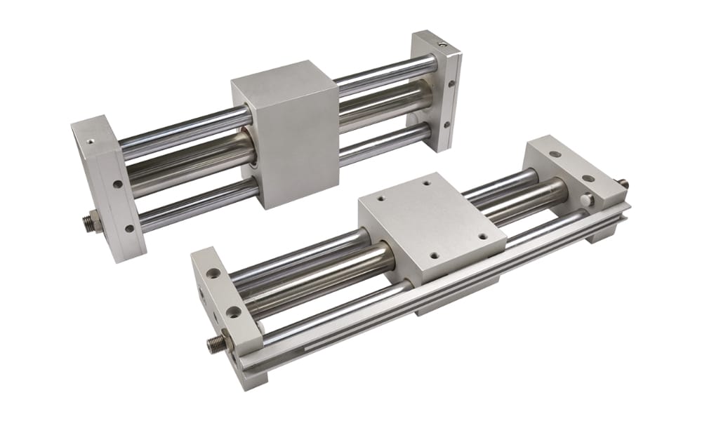
Magnetic coupling can remove one open-slot contamination path. It doesn’t eliminate guide wear, internal lubrication, internal leakage, or the need to verify the exact model under realistic test conditions.
Check these actuator details:
- exact model, bore, stroke, mounting orientation, speed range, load, moment, cycle rate, test chamber, sampling method, and background concentration;
- grease type and quantity, re-lubrication rule, seal material, guide treatment, and service procedure;
- relief or vacuum-port flow and tubing limits;
- external fasteners, recesses, labels, switches, cable jackets, exposed adhesives, cleaning access, and compatibility with the validated cleaning process over its planned life;
- packaging and clean-opening instructions.
For slow, force-sensitive motion, cleanroom suitability still doesn’t establish stable low-speed performance. Review the separate guide to low-friction cylinders in medical-device manufacturing before assuming low particle generation also guarantees precise positioning; seal friction, load, pressure, and speed still change the result.
Valves, Regulators, Silencers, and Exhaust
Keep valves outside the critical zone when practical. If a valve must sit close to exposed product, review the external materials and internal grease first. Then check leakage, coil heat, exhaust direction, silencer media, cleaning compatibility, and particle evidence for the exact configuration.
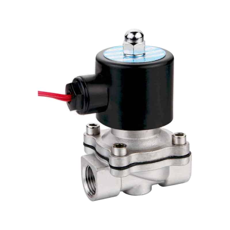
A stainless valve body solves only part of the selection problem. Internal seals, grease, coil temperature, leakage, packaging, and the connected exhaust path still need separate model-specific evidence before acceptance.
Avoid treating a standard porous silencer as a cleanliness control. It may reduce noise while placing an unqualified medium directly in the exhaust stream. Remote exhaust can be better, but long or undersized exhaust tubing adds backpressure and can slow the actuator. Measure both cleanliness and motion.
Fittings, Tubing, Sensors, and Small Parts
Small components create many interfaces. Specify tube material, inner and outer diameter, bend radius, permeation, outgassing, cleaning compatibility, electrostatic behaviour where relevant, and the exact fitting seal. Keep threaded joints and sealants away from exposed product when the layout permits. Electrical items need the same discipline. Confirm sensor housing and cable-jacket materials, flex life, heat, surface cleanability, connector location, and packaging. Connecting a clean actuator to an unsuitable cable carrier doesn’t produce a clean assembly.
How Do You Preserve Force, Speed, and Service Life in a Cleanroom Design?
SMC’s CYP32-200 particle data used a 5 kg load, 200 mm/s average speed, and 500,000 operating cycles; the catalog says the result is a selection guide, not a guarantee (SMC CYP catalog, accessed 2026). Performance outside that test envelope needs separate confirmation.
Cleanroom controls can change pneumatic behaviour in several connected ways. A vacuum extraction line adds flow demand, while remote valve exhaust can create backpressure and fine point-of-use filtration adds pressure drop. Longer tubing increases dead volume and response delay. Lower pressure may protect a magnetic coupling but reduce thrust. Can the cylinder still finish before the machine timeout? Use the same operating envelope for cleanliness and motion acceptance:
| Variable | Performance risk | Cleanliness risk |
|---|---|---|
| Pressure | Insufficient force or broken magnetic coupling if outside limits | Higher leakage or operation beyond tested condition |
| Speed and acceleration | Cycle-time loss, overshoot, shock, unstable motion | More seal, guide, and end-impact particle generation |
| Load and moment | Deflection, binding, guide wear, shortened life | Higher contact pressure and debris |
| Valve and tube flow | Slow stroke, pressure collapse, asymmetric motion | Larger hardware or exhaust disturbance near the product |
| Vacuum or relief flow | Added energy use and plumbing | Poor capture if flow or tubing falls outside the test boundary |
| Cleaning exposure | Swollen seals, damaged coatings, sensor failure | Residue, corrosion, shedding, or loss of surface integrity |
Start with load, stroke, cycle time, pressure, mounting, and allowable moment. Then select a component whose cleanroom configuration can meet those values without exceeding its tested cleanliness envelope. Don’t derate by guesswork. Ask the supplier for both the ordinary performance limits and any clean-series limits because they may differ. Our team found a useful comparison. Place the ordinary datasheet beside the cleanroom supplement; differences in maximum pressure, speed, permitted grease, maintenance procedure, or port use expose constraints that a cleanroom-class label leaves out.
Check system pressure drop and point-of-use air quality together. The guide to ISO compressed-air quality standards explains how to write particle, water, and oil classes, while the coalescing-filter guide covers oil-aerosol control and maintenance boundaries.
What Evidence Should a Supplier Provide?
Festo gives a useful example: a component above a workpiece may need ISO Class 4 performance while one below it may be acceptable at ISO Class 7 (Festo cleanroom guidance, accessed 2026). Supplier evidence must therefore name the installation position and operating parameters.
Equipment suitability is a test-supported statement that a named configuration meets a defined particle or chemical limit under recorded conditions. It is narrower and more useful than saying a whole product family is “cleanroom compliant.” Ask for the report behind the claim. Strong particle reports identify the exact model and revision, sample quantity, mounting position, speed, load, pressure, cycle count, background concentration, particle sizes, counter, probe location, chamber arrangement, test duration, data treatment, uncertainty, and measured result. Record active vacuum or relief flow with its plumbing. Chemical reports should name the substances, detection limits, test temperature, conditioning time, exposed material area, and cleaning state. They should also say whether the result covers the delivered grease, seals, adhesives, cable, and packaging. Generic “low outgassing” language doesn’t reveal what was measured.
Material evidence should match the actual risk:
- certificates for metal grade, polymer identity, coating, grease, restricted substances, production revision, traceability, lot or batch, and issue date where required;
- measured finish and test method;
- chemical-compatibility evidence for the exact agent, concentration, temperature, contact time, number of cycles, and inspected failure modes;
- pathway-specific biological evidence;
- packaging, assembly, shelf-life, opening, and handling records when the delivered cleanliness state forms part of acceptance.
ASTM B912 covers passivation of stainless steel by electropolishing and notes improved corrosion resistance from removing surface free iron (ASTM B912, 2026). It doesn’t establish an automatic Ra 0.4 µm finish. If roughness matters, put the numeric limit and measurement method on the drawing. Supplier certificates are strongest when they preserve the conditions under which the claim is true. Don’t collect documents for volume alone. Make every cleanliness claim traceable to a part number, configuration, test state, acceptance limit, and named gap that still requires installed qualification.
How Should You Qualify the Installed Pneumatic Assembly?
EU GMP Annex 1 gives 10 Pa as a minimum guidance value between adjacent rooms of different grades and requires airflow studies at rest and in operation (European Commission, EU GMP Annex 1, 2022). Qualify moving and exhausting pneumatic equipment within that installed airflow.
Supplier testing is screening evidence. Installation qualification must reproduce the real contamination path: mounting position, surrounding surfaces, product exposure, airflow, valve location, exhaust routing, tubing, operating pressure, load, speed, cycle pattern, cleaning state, and maintenance condition. If the process is pharmaceutical, connect those controls to the facility contamination-control strategy. Consider a clean-tested cylinder whose valve exhaust points across the sampling location. The cylinder report may remain valid, yet the installed axis can still disturb protected airflow or release contamination from the valve and silencer. Qualification must test the assembly that the process actually sees.
A practical qualification sequence is:
- Freeze the bill of materials, part revisions, grease, seals, fittings, tubing, valve, silencer, filters, mounting drawing, and software motion profile.
- Define particle, chemical, viable, surface, and performance acceptance criteria separately. Not every project needs every category, but each omitted category should have a documented risk-based reason that quality and engineering can review.
- Establish background conditions at rest, then run normal production and the worst credible operating cases.
- Sample at plausible release paths and product-risk locations. Record probe position so the test can be repeated.
- Verify force, pressure, speed, stroke time, repeatability, leakage, temperature, vacuum or relief flow, and machine fault behaviour during the same test state.
- Repeat after run-in and near maintenance.
- Define requalification triggers for seal replacement, grease change, tubing change, new cleaning chemistry, altered speed, software motion changes, or a new installation position.
Would a chamber test detect exhaust aimed across an open vial or a side-loaded guide wearing faster than expected? Usually not. The installed test closes that gap. For long-term control, use the broader pneumatic actuator maintenance comparison. Cleanroom work adds controlled packaging, tools, cleaning, contamination recovery, recorded part revisions, and requalification to ordinary leakage and wear checks.
What Should You Put on a Class 100 Pneumatic RFQ?
ISO 8573-1 separates compressed-air purity into three main contaminant groups: particles, water, and oil, independent of where the air is specified or measured (ISO 8573-1, 2010). A strong Class 100 RFQ applies that clarity to each contamination path and every vendor response.
Use that same clarity for the entire RFQ. Point-of-use air quality is the measured or specified condition where compressed air enters the process connection or relevant valve and actuator. A compressor-room result can’t represent downstream piping or dryers. It also misses contamination introduced by filters and condensate. Lubricators and maintenance add further uncertainty.
Send the application conditions, not just the room class, beginning with cleanliness and motion:
| RFQ field | Information to provide | Evidence to request |
|---|---|---|
| Critical location | Drawing, airflow direction, distance and position relative to product | Tested position, release direction, probe location |
| Particle target | ISO class, particle sizes, room state, background and limit | Model-specific particle report and operating envelope |
| Chemical target | Restricted substances and concentration limits | Outgassing or chemical-emission method and result |
| Viable/product risk | Sterile boundary, gas contact and product exposure | Material, gas-filtration and cleaning evidence that fits the pathway |
| Motion | Load, stroke, speed, acceleration, cycle rate, orientation and moment | Clean-series pressure, speed, load, life and derating data |
Then define the surrounding pneumatic system and delivery state:
| RFQ field | Information to provide | Evidence to request |
|---|---|---|
| Air supply | Point-of-use particle, water and oil classes; dew point and pressure | Required filtration, dryness and lubrication conditions |
| Exhaust/suction | Valve position, remote exhaust, vacuum availability and tube length | Port arrangement, minimum flow, backpressure and filter limits |
| Materials/cleaning | Agents, temperature, contact time, cycles and restricted materials | Exact seal, grease, metal, coating and compatibility records |
| Maintenance | Access, planned interval and allowed intervention | Seal kit, grease rule, clean work instructions and requalification trigger |
| Delivery | Transfer route and opening environment | Assembly, cleaning, double-bagging and shelf-life statement |
Use three labels for every supplier gap: “not tested” / “not applicable” / “requires installed qualification.” That wording is more valuable than an unsupported compliance promise. It lets engineering and quality teams decide where additional testing is worth the cost. Visible gaps are actionable.
From our work on application reviews, supplier replies become easier to compare when every RFQ uses the same test fields. The objective isn’t a universal certificate. It separates documented performance from engineering inference. It also identifies evidence that still has to be generated on the installed machine.
Conclusion: Select the Evidence Boundary, Not the Label
Three equipment-related ISO cleanroom standards were revised in 2026: Parts 13 and 14 were published in February, and Part 15 followed in May (ISO 14644-13, 2026; ISO 14644-14, 2026; ISO 14644-15, 2026). They give separate boundaries for surface cleaning, airborne particles and airborne chemicals.
Trace contamination from the exposed process back through the actuator and valve. Continue through the exhaust, fittings, tubing and compressed air. Include grease, sensors, packaging and maintenance work. Then compare supplier claims with the real load, speed and pressure. Check the position, cleaning process and sampling plan separately. The best component isn’t automatically the one with the most stainless steel or the strictest class printed on its catalog page. It is the configuration that meets the documented cleanliness limit without losing the motion performance the machine requires. Prove both under the same operating conditions.
FAQs About Class 100 Cleanroom Pneumatic Components
SMC recommends maintaining one CYP clean rodless cylinder at roughly 500,000 cycles or 400 km of travel to preserve its stated particle characteristics (SMC CYP catalog, accessed 2026). That model-specific boundary illustrates why cleanroom FAQs need conditions rather than universal promises.
Does ISO Class 5 certify a pneumatic component?
No. ISO 14644-1 classifies airborne particle concentrations across threshold sizes from 0.1 µm to 5 µm. ISO 14644-14:2026 provides the equipment-suitability method. Ask for the exact component, position, speed, load, pressure, particle size, sampling geometry, background concentration, cycle count, and measured result.
Must every Class 100 pneumatic component use 316L and PTFE?
No. ISO 14644-14:2026 explicitly excludes equipment design and material-selection requirements. Base the selection on actual particle and chemical risk. Then check corrosion and cleaning limits, operating temperature and product contact. Record a numeric finish requirement only when the cleaning or process assessment supports it.
Can a standard industrial component be used in a cleanroom?
Sometimes. Festo’s application example distinguishes an ISO Class 4 requirement above a workpiece from ISO Class 7 below it. Suitability depends on position and operating parameters. Treat untested components as a qualification gap. Control or test their emissions and surfaces, then include packaging, exhaust, and maintenance state.
How often should cleanroom pneumatic components be serviced?
Use model-specific limits and site trend data. SMC gives roughly 500,000 cycles or 400 km for one CYP clean rodless cylinder, not for every actuator. Set the interval from leakage and particle trends. Also examine guide wear and cycle count. Include cleaning exposure, grease condition and criticality. Consider the consequences of opening the system.
What documentation belongs in the validation package?
At minimum, connect the part number to particle evidence under ISO 14644-14. Add chemical evidence when ISO 14644-15 applies and point-of-use air specifications for the three ISO 8573-1 contaminant groups. The package should also hold drawings and material records, grease and cleaning compatibility, packaging and maintenance instructions, the test setup and raw results, deviations, and requalification triggers.
Source Notes and Retrieval Dates
-
ISO 14644-1:2015, airborne particle classification scope and exclusions. Retrieved 2026-07-17.
-
ISO 14644-13:2026, surface cleaning to defined particle and chemical cleanliness levels. Retrieved 2026-07-17.
-
ISO 14644-14:2026, equipment suitability by airborne particle concentration and scope exclusions. Retrieved 2026-07-17.
-
ISO 14644-15:2026, equipment and material suitability by airborne chemical concentration and scope exclusions. Retrieved 2026-07-17.
-
ISO 8573-1:2010, compressed-air particles, water, oil, gaseous and microbiological contaminants. Retrieved 2026-07-17.
-
FDA Aseptic Processing Guidance, Class 100/ISO 5 terminology, particle limit, compressed-gas quality and equipment design. Retrieved 2026-07-17.
-
European Commission, EU GMP Annex 1, contamination-control strategy, equipment, utilities, surfaces, pressure and airflow qualification. Retrieved 2026-07-17.
-
SMC CQ2 Clean Series, double-seal, relief-port and vacuum-port clean-cylinder examples. Retrieved 2026-07-17.
-
SMC CYP Clean Rodless Cylinder, particle-test conditions, operating limits, maintenance boundary and caveats. Retrieved 2026-07-17.
-
Festo Cleanroom Guidance, application position and operating-parameter dependence. Retrieved 2026-07-17.
-
USP General Chapter 88: Biological Reactivity Tests, In Vivo, scope of polymer biological-reactivity testing. Retrieved 2026-07-17.
-
ASTM B912-26, stainless-steel passivation by electropolishing. Retrieved 2026-07-17.