

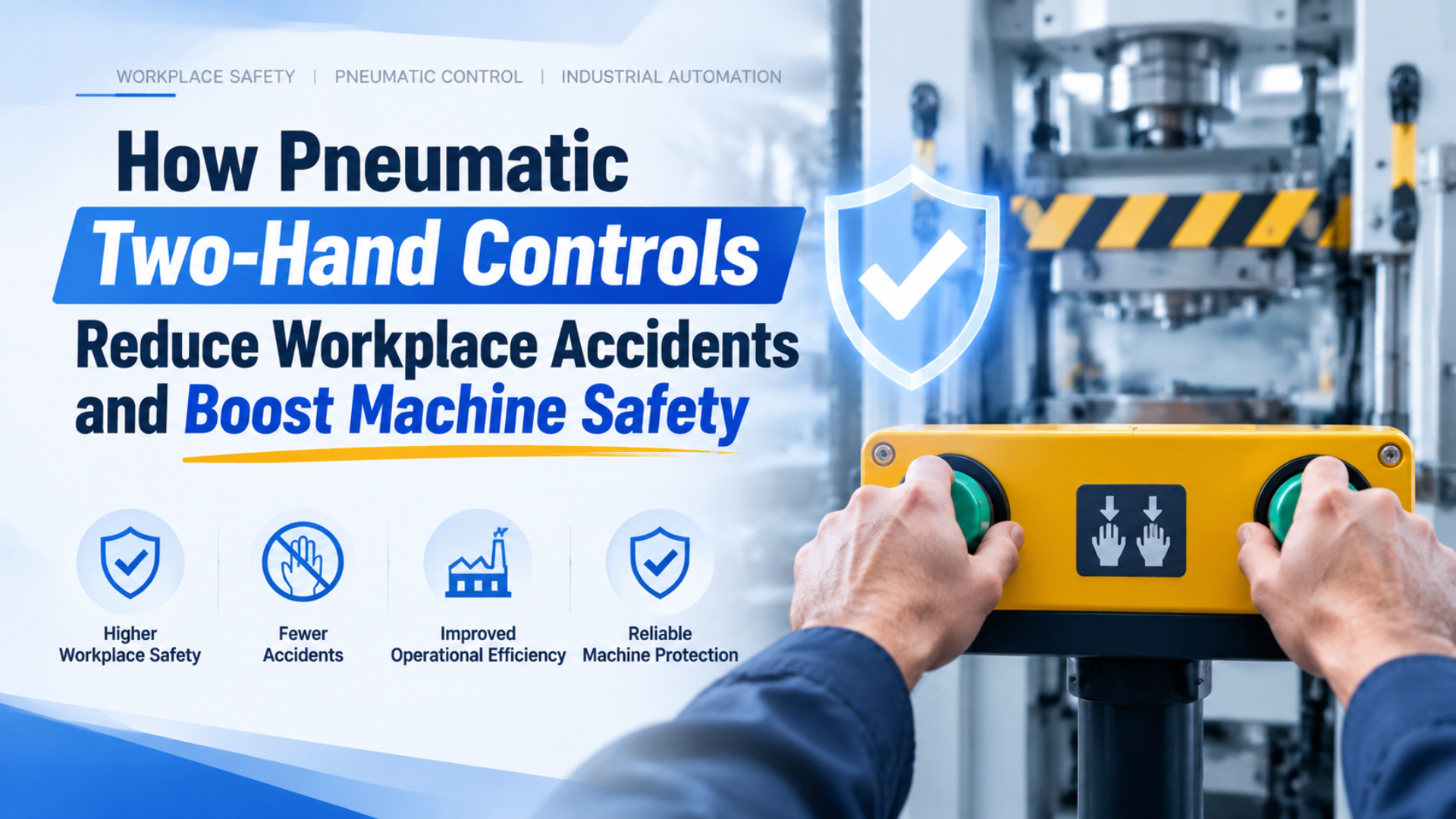
Pneumatic two-hand controls reduce machine-start hazards by requiring an operator to place both hands on separate actuators before a hazardous cycle can begin. A correct system also checks timing, prevents a held or bypassed button from enabling repeated cycles, locates the controls beyond the calculated danger-zone reach, reacts safely to faults, and validates the complete machine response.
That is a narrower claim than “two buttons prevent accidents.” A two-hand device protects the person using it only while the safety function keeps that person’s hands at a known location. It doesn’t automatically protect a coworker, prevent side access, remove stored pneumatic energy, restrain a suspended load, or certify the surrounding valve circuit.
Two-hand control device (THCD) is a protective device whose output depends on hand actuation of two control actuators. Two-hand trip initiates a cycle through concurrent actuation but may let the operator release the controls afterward. Safety function is the complete risk-reduction behavior, including input, logic, output, machine response, reset, and fault reaction.
Key Takeaways
- ISO 13851:2019 defines 3 THCD types but says the device protects only its user.
- OSHA press safety distance is calculated from stopping or closing time, not a universal 600 mm rule.
- Two ordinary pushbutton valves plus an AND element don’t prove an achieved Performance Level.
- Validation must test the installed safety function and credible faults.
What Do Pneumatic Two-Hand Controls Actually Protect?
ISO 13851:2019 defines functional combinations for 3 types of two-hand control device, yet it explicitly says a THCD protects only the person using it (ISO 13851, confirmed 2024). The device reduces risk by keeping that operator’s hands occupied and away from the hazard during the relevant part of the cycle.
This protection depends on several conditions remaining true. Both actuators must require deliberate hand actions. Their locations must prevent the operator from reaching the hazard before it becomes safe. The machine must respond as specified when either hand is removed, when a fault occurs, or when the supply changes. The next cycle must not begin from a button that remains held.
The protection boundary is equally important. ISO 13851 does not say which machines must use a THCD or which of its three types fits every application. It directs selection back to the machine risk assessment and any applicable type-C machinery standard. A press, shear, clamp, fixture, and assembly station can have very different closing behavior and access routes.
OSHA’s general machine-guarding rule requires one or more methods of guarding where machine operation exposes employees to injury. It lists two-hand tripping devices as one possible method, alongside guards and electronic devices (OSHA 29 CFR 1910.212). The method still has to prevent body access to the danger zone during the operating cycle.
A two-hand device controls one person’s starting posture. It does not control the entire access perimeter. If another employee can reach the hazard from the side or rear, the solution needs additional guarding, interlocking, presence sensing, separation, or a different work method.
Two-Hand Control and Two-Hand Trip Are Different Functions
OSHA defines a two-hand control on a mechanical power press as a device requiring concurrent pressure during a substantial part of die closing, while a two-hand trip only requires concurrent use to initiate the clutch (OSHA Press Definitions). The difference determines whether releasing one hand can still stop hazardous motion.
For a part-revolution clutch press, OSHA explains that the operator holds both controls during the dangerous portion of the downstroke. Releasing either control disengages the clutch, applies the brake, and stops slide motion. A full-revolution press using a two-hand trip behaves differently: after initiation, the slide normally completes its cycle and the operator’s hands are free (OSHA clarification).
| Function | What the operator does | What happens after release | Primary engineering concern |
|---|---|---|---|
| Two-hand control | Presses both actuators concurrently and continues holding them as required | Releasing either input must produce the specified stop behavior | Stopping performance, safety distance, control reliability |
| Two-hand trip | Presses both actuators concurrently to initiate the cycle | Motion may continue after release | Distance must prevent reaching the hazard before closure completes |
| Ordinary dual command | Provides two normal control signals | Depends entirely on ordinary logic and valves | Not automatically a safety function |
These OSHA details apply specifically to mechanical power presses under 29 CFR 1910.217. Other machines require their own risk assessment and applicable machinery standards. Don’t copy a press control arrangement onto a pneumatic clamp or custom fixture without checking how the hazard stops, coasts, traps pressure, or moves after air loss.
In our experience, many retrofit errors begin with the wrong functional description. The drawing says “two-hand start,” but the risk assessment assumes “release either hand and motion stops.” Those are not interchangeable requirements. State the expected response to each input transition before choosing hardware.
How Should Risk Assessment Define the Required Safety Function?
ISO 12100:2010 provides a machinery risk-assessment and risk-reduction method covering hazard identification, risk estimation, evaluation, protective measures, documentation, and verification (ISO 12100, confirmed 2022). A THCD should be selected only after this process defines who is exposed, when access occurs, and what safe behavior the machine must achieve.
Start with the task, not the button catalog. Observe normal loading, alignment, cycling, unloading, adjustment, fault recovery, cleaning, and foreseeable misuse. Identify the point of operation, pinch zones, ejected material, secondary axes, hot tooling, stored pressure, and gravity-loaded mechanisms. Then determine which people can enter each hazard zone.
Define the safety function in measurable terms:
| Safety-function element | Question to answer | Required evidence |
|---|---|---|
| Initiation | Which two actuators must be operated, and within what permitted timing behavior? | Input specification and timing test |
| Continued actuation | Must both hands remain present, and for which hazardous portion? | Cycle and release-response test |
| Safe distance | How long can hazardous motion continue after release or initiation? | Measured stopping or closing time |
Complete the definition with the restart, fault, output, and integrity requirements:
| Safety-function element | Question to answer | Required evidence |
|---|---|---|
| Reset | What must happen before another output is allowed? | Anti-repeat and restart test |
| Fault reaction | Which single or combined faults must inhibit the next cycle or stop motion? | Fault list and injection results |
| Output behavior | Must the machine stop, exhaust, hold pressure, return, or remain clamped? | Pneumatic and mechanical response trace |
| Performance | What PLr or other integrity target applies? | Risk assessment and safety calculation |
The result may show that a THCD is unsuitable. An operator who must hold a workpiece near the die cannot use two hand controls as intended. A process with several exposed people may need perimeter guarding or presence sensing. A machine that cannot stop before access may need a fixed barrier or a trip positioned from the full closing time.
For pneumatic hazards, also define the safest energy state. The safety exhaust valve integration guide explains why venting is helpful for some hazards but can release clamps or allow vertical loads to fall in others.
Why Aren’t Two Pushbutton Valves and an AND Valve Enough?
ISO 13849-1:2023 applies to safety-related control-system parts using electrical, hydraulic, pneumatic, and mechanical technologies, but it does not prescribe the safety function or PLr for a particular machine (ISO 13849-1, 2023). Two air signals can create Boolean AND logic without providing the architecture, reliability, diagnostics, or fault response required for safety.
A standard dual-pressure valve may produce an output only when both inlets are pressurized. That proves the intended truth table under normal conditions. It says nothing about a stuck pushbutton, crossed tube, blocked exhaust, internal spool fault, shared supply failure, pressure retained at one input, or an output valve that fails to shift.
The complete safety-related control system can include:
- two protected hand actuators;
- input signal paths and synchronization monitoring;
- anti-tie-down and anti-repeat logic;
- a safety controller or validated pneumatic logic unit;
- one or more output elements;
- diagnostic feedback or pressure monitoring;
- the actuator and mechanical stopping behavior;
- reset and restart logic;
- controlled wiring, tubing, software, and documentation.
Category and Performance Level are not interchangeable labels. Category describes architectural behavior under faults. Achieved PL also depends on component reliability, diagnostic coverage, common-cause measures, mission time, and other design data. A component marketed as “Category 3 capable” doesn’t make every circuit Category 3 or PL d.
The existing guide to pneumatic logic valves shows how AND and OR functions work in ordinary circuits. Its safety boundary is deliberate: a normal logic component should not be credited as a THCD unless its documentation and the complete validated architecture support that use.
The Boolean expression A AND B is the smallest part of the problem. Machine safety depends on whether A and B are independent enough, whether faults are detected, whether the output really reaches the safe state, and whether a held input can enable the next cycle.
How Is the Safety Distance Determined?
For part-revolution mechanical power presses, OSHA requires the two-hand control distance to exceed Ds = 63 inches/second × Ts, where Ts is measured stopping time (OSHA 1910.217(c)(3)(vii)(c)). A two-hand trip uses a different closing-time formula. Neither rule supports a universal 600 mm installation distance.
The distance must correspond to the actual safeguarding function and machine. A control arrangement that stops motion after release needs the worst credible total stopping time. A trip that cannot interrupt the cycle needs the time until the point of operation is no longer reachable or hazardous. Applicable standards may add a measurement tolerance, response allowance, or machine-specific requirement.
Use this measurement chain:
- Identify the exact safety input event, such as release of either hand actuator.
- Measure logic and output response, not merely valve catalog switching time.
- Measure hazardous mechanical stopping or closing behavior at the relevant position.
- Test the slowest stopping condition over pressure, load, speed, temperature, and wear ranges.
- Apply the formula and allowances required by the governing standard.
- Fix the control station so unauthorized relocation cannot reduce the distance.
- Revalidate after brake, valve, tooling, pressure, speed, or control changes.
Don’t substitute cylinder stroke time from a general calculator for measured safety response. Flow, load, cushioning, exhaust restrictions, friction, brake condition, and stored energy affect real motion. A theoretical result may help engineering estimates, but it cannot certify the installed safety distance.
The same caution applies to a quoted 500 ms. Some two-hand devices publish a permitted simultaneity window for their inputs. That number is not the machine’s stopping time, the valve exhaust time, or a universal safety-distance value. Record each timing requirement separately.
How Should the Controls Resist Defeat and Unexpected Restart?
OSHA 1910.217 requires mechanical-press hand controls to be protected against unintended operation and arranged by construction or separation to require both hands (OSHA 1910.217(b)(6)-(7)). For multiple operators, the standard requires separate controls and concurrent application. The principle is broader: foreseeable bypass must be designed out and tested.
Button separation alone is not enough. An operator may use one hand and an elbow, lean an object on one actuator, tape a valve down, bridge two electrical contacts, or hold one pneumatic input pressurized. Control placement, shrouds, actuator shape, signal monitoring, and reset logic should make those defeat methods ineffective.
An effective sequence normally prevents these conditions:
- one actuator is pressed before the sequence is ready;
- one actuator remains held while the other is released and pressed again;
- both actuators are held through reset or pressure restoration;
- a short pressure pulse is trapped long enough to satisfy the logic;
- an output remains on after one input is removed when release should stop motion;
- a fault is acknowledged without restoring the intended safe state;
- automatic air restoration initiates hazardous movement.
Control ergonomics still matter. Actuators should allow a neutral working posture and clear view without encouraging a worker to defeat the system. But there is no universal shoulder height or 15-degree mounting rule. Evaluate operator size range, gloves, reach, force, workstation adjustment, visibility, and the safety distance together.
In our experience, the best anti-defeat review is physical. Ask someone unfamiliar with the design to identify how an operator might keep one input active, reach around the station, or move the controls closer. Then test those attempts under a controlled commissioning procedure rather than trusting the drawing alone.
What Must the Pneumatic Output Do After a Safety Demand?
Festo defines the pneumatic THC subfunction simply: simultaneous two-hand actuation activates an output signal (Festo Pneumatic Safety). That output signal is not the safe state itself. The downstream valves, actuators, loads, and stored energy must produce the risk-assessed machine response when either input is removed or a fault is detected.
Possible responses include stopping and holding pressure, blocking supply, exhausting a defined zone, controlled return, mechanical braking, or a combination. Immediate exhaust is not always safest. A vertical cylinder can descend, a clamp can release a workpiece, and vacuum tooling can drop a load after pressure is removed.
Review the complete output path:
| Output concern | Failure question | Verification method |
|---|---|---|
| Directional valve | Can the spool stick or one channel fail to switch? | Fault injection and position or pressure feedback |
| Exhaust path | Can a fitting, silencer, tube, or check valve delay venting? | Pressure trace under worst-case restriction |
| Cylinder | Can gravity, spring force, or trapped pressure continue motion? | Loaded motion test at pressure extremes |
| Load holding | Does air loss release a clamp or suspended tool? | Energy analysis and mechanical restraint test |
| Restart | Can pressure restoration create motion without a new valid command? | Power and air cycling test |
| Diagnostics | Does a detected discrepancy inhibit the next hazardous cycle? | Deliberate feedback and channel faults |
A safety exhaust valve may perform the blocking and venting part of the function. A cylinder rod lock may help restrain a compatible axis. Neither component should be credited beyond its documented behavior and installed validation.
Ordinary valves still need correct pressure, flow, exhaust, and environmental selection. The article on manual and mechanical valve selection is useful for normal command functions, but ordinary mechanical valves are not automatically safety-rated hand actuators.
Validation of the Complete Safety Function
ISO 13849-2:2012 requires validation by analysis and testing of the specified safety functions, achieved Category, and achieved Performance Level for systems designed under ISO 13849-1 (ISO 13849-2, current edition pending revision). Validation therefore covers the installed machine and documented fault response, not just certificates for individual components.
Build the validation plan from the safety requirements specification. Each requirement needs an acceptance result, test condition, instrument, expected response, actual response, and reviewer. Record the machine configuration because changes to tooling, pressure, speed, valves, software, tubing, or exhaust can alter stopping behavior.
Minimum test coverage should include:
- normal concurrent actuation and release of each input;
- one input arriving too early or remaining held;
- attempted repeat cycle without full release and reset;
- one input tube disconnected, crossed, restricted, or held pressurized;
- logic or output channel failing to change state;
- diagnostic feedback stuck on and stuck off;
- minimum and maximum allowed supply pressure;
- worst-case load, speed, stroke position, and stopping condition;
- loss and restoration of electrical power and compressed air;
- blocked or restricted exhaust where reasonably foreseeable;
- reset after a demand and after a detected fault;
- access by another person or through another side of the machine.
Capture input states, safety output, valve feedback, downstream pressure, and hazardous motion on a common time base when timing matters. A stopwatch watching a pilot light is not enough for a safety-distance measurement. Document the measurement uncertainty and use the relevant machine standard’s required method.
In our experience, a useful validation report makes replacement decisions easier years later. It records part numbers, revisions, B10d or PFHd data where applicable, pneumatic diagrams, software checksums, pressure settings, test instruments, stopping-time results, fault tests, and approved alternatives.
How Should Maintenance, Retrofit, and Servicing Be Managed?
OSHA 1910.147 covers servicing where unexpected startup or stored-energy release can injure workers and explicitly includes pneumatic energy (OSHA Lockout/Tagout). Pushbuttons and control-circuit devices are not energy-isolating devices. A two-hand control protects a production task; it does not replace lockout, stored-energy control, or verification.
Set inspection and test intervals from the manufacturer instructions, machine risk assessment, applicable standards, operating frequency, contamination, history, and change control. Don’t invent one daily, weekly, or annual schedule for every THCD. A high-cycle press in an oily environment and a guarded fixture used twice per shift do not have the same exposure.
Maintenance should verify more than button movement:
- actuator guards, shrouds, mounting, labels, and tamper resistance;
- input channels, tubing or wiring, connectors, and exhaust paths;
- synchronization, anti-tie-down, anti-repeat, and reset behavior;
- output valve response and diagnostic feedback;
- stopping time or closing time when the maintenance plan requires measurement;
- fixed control location and calculated safety distance;
- guards and protective devices for other exposed people;
- pneumatic isolation, bleed-down, restraint, and LOTO procedure.
A retrofit needs the same rigor as a new design. Replacing a foot pedal with two palm buttons may change how the machine starts, but it does not automatically create control reliability, adequate stopping performance, or protection for other employees. Measure the machine, define the safety function, redesign the architecture, and validate the completed modification.
For ordinary pneumatic architecture outside the safety subsystem, modular valve circuit guidance can help organize supplies and functions. Keep its normal control channels distinct from the safety-related channels and documentation.
Frequently Asked Questions About Pneumatic Two-Hand Controls
ISO 13851:2019 contains 21 pages and defines three functional THCD types, but it does not choose a device type or safety distance for every machine (ISO 13851). These answers therefore state design boundaries rather than universal dimensions, response times, categories, or inspection intervals.
What is the minimum spacing between two-hand control buttons?
There is no universal 600 mm rule in ISO 13851. The arrangement must require both hands and resist foreseeable defeat, while the complete control station must remain beyond the applicable safety distance from the hazard. Use the machine risk assessment, applicable type-C standard, ergonomic review, and validated reach or stopping calculation.
Must both buttons be pressed within 500 ms?
Some certified devices publish a specific simultaneity window, but use the selected product and governing standard’s requirement. Don’t confuse input synchronization with machine stopping time. Safety distance depends on the relevant total stopping or closing behavior, including logic, valves, mechanics, load, and measurement allowances.
Can a standard pneumatic AND valve be used for two-hand control?
It can demonstrate normal AND logic, but that alone does not establish a compliant THCD. Safety may require protected inputs, synchronization, anti-tie-down, anti-repeat, fault detection, defined reset behavior, documented component reliability, an appropriate architecture, a safe output subsystem, and validation of the installed machine.
Does every pneumatic two-hand control need Category 3 or Category 4?
No. ISO 13849-1 doesn’t specify the required PLr for a particular machine. Determine the required risk reduction from the risk assessment and applicable machinery standard. Then design the complete safety-related control system and calculate or validate its achieved Performance Level, including architecture, reliability, diagnostics, and common-cause measures.
Does releasing either hand always stop the machine?
Not for every two-hand device. A two-hand control is intended to require continued actuation during a defined hazardous portion, while a two-hand trip can initiate a cycle that continues after release. The risk assessment, machine design, governing standard, and safety requirements must state the expected release response.
Can two-hand controls replace fixed guards or lockout/tagout?
No. ISO 13851 says a THCD protects only its user, so other people and access routes may require guards or additional protective devices. For covered servicing, OSHA 1910.147 requires energy isolation, control of stored or residual energy, and verification. A pushbutton command is not an energy-isolating device.
Final Engineering Checklist
ISO 13851 defines 3 THCD types, while ISO 13849-1 applies across pneumatic, electrical, hydraulic, and mechanical safety-related control technologies (ISO 13851; ISO 13849-1). Use the two standards together with the machine risk assessment and applicable type-C requirements, not as interchangeable component labels.
-
The risk assessment defines the hazard, exposed people, operating modes, and foreseeable misuse.
-
The safety requirements distinguish a two-hand control from a two-hand trip.
-
Both actuators require deliberate hand operation and resist foreseeable defeat.
-
Timing, anti-tie-down, anti-repeat, release, and reset behaviors are specified.
-
Safety distance is based on the applicable measured stopping or closing time.
-
The control station cannot be moved inside the validated distance without authorization.
-
The required PLr or other integrity target comes from the risk assessment, not a valve label.
-
Inputs, logic, outputs, feedback, actuator behavior, and mechanical response are included.
-
Air loss, power loss, trapped pressure, gravity, springs, and suspended loads reach a safe condition.
-
Other operators and access routes have appropriate guarding or protective devices.
-
Credible faults are injected and the installed response is recorded.
-
Production safeguarding is kept distinct from servicing lockout/tagout.
-
Changes to tooling, pressure, speed, valves, tubing, software, or controls trigger review.
Pneumatic two-hand controls can be an effective part of machine safeguarding because they require two deliberate inputs and keep the activating operator’s hands at a known location. Their real value comes from the surrounding engineering: risk assessment, correct function selection, measured safety distance, anti-defeat design, reliable output behavior, and documented validation.
If you need help reviewing a pneumatic safety circuit, learn more about our engineering background or send the machine details. Include the hazard, machine type, operating sequence, pressure, valve architecture, stopping-time data, control drawings, exposed people, and required regional standards.
Sources
-
International Organization for Standardization. ISO 12100:2010, Safety of machinery, risk assessment and risk reduction. Confirmed 2022. Retrieved July 17, 2026.
-
International Organization for Standardization. ISO 13849-1:2023, Safety-related parts of control systems. Retrieved July 17, 2026.
-
International Organization for Standardization. ISO 13849-2:2012, Validation. Retrieved July 17, 2026.
-
International Organization for Standardization. ISO 13851:2019, Two-hand control devices. Confirmed 2024. Retrieved July 17, 2026.
-
Occupational Safety and Health Administration. 29 CFR 1910.147, Control of hazardous energy. Retrieved July 17, 2026.
-
Occupational Safety and Health Administration. 29 CFR 1910.212, General machine guarding requirements. Retrieved July 17, 2026.
-
Occupational Safety and Health Administration. 29 CFR 1910.217, Mechanical power presses. Retrieved July 17, 2026.
-
Occupational Safety and Health Administration. Mechanical power press definitions. Retrieved July 17, 2026.
-
Occupational Safety and Health Administration. Mechanical power press clarifications. Retrieved July 17, 2026.
-
Festo. Pneumatic safety subfunctions, including two-hand control. Retrieved July 17, 2026.