

A pneumatic pressure booster uses compressed air to raise the pressure of a smaller air or gas flow without an electric motor. In factory automation, a booster regulator is useful when one local device needs more pressure than the plant header can provide and the demand is limited enough for the booster and receiver to recover between events.
That does not make a booster essential everywhere. A dirty filter, undersized hose, weak regulator, or poorly sized receiver can create the same low-pressure symptom. The right sequence is to measure pressure while the machine works, remove avoidable restrictions, quantify the high-pressure demand, and then decide whether local boosting is the most efficient solution.
Key Takeaways
- SMC’s standard VBA booster regulators provide up to about 2× inlet pressure; one VBA11A version reaches 4×.
- Size from both average and maximum instantaneous flow, not pressure alone.
- Fix avoidable pressure drop before adding boost capacity.
What Is a Pneumatic Pressure Booster—and Which Type Do You Mean?
A factory-air booster regulator and a high-pressure gas booster are not the same device. SMC lists standard VBA regulators at up to 2× inlet pressure and a VBA11A at 4×, while Haskel lists air amplifiers with 8:1, 15:1, and 30:1 area ratios (SMC, 2026; Haskel, 2026).
Use the device family name before comparing specifications:
| Device family | What is boosted | Typical purpose | Selection basis |
|---|---|---|---|
| Booster regulator | A portion of factory compressed air | Local machine pressure above the plant header | Inlet pressure, set pressure, outlet flow curve, cycle demand, receiver size |
| Air pressure amplifier | Compressed air | Higher air pressure for testing, clamping, or charging | Drive pressure, inlet assistance, area ratio, stall pressure, displacement per cycle |
| Air-driven gas booster | Nitrogen, helium, hydrogen, oxygen, or another compatible gas | Gas transfer, cylinder charging, leak or pressure testing | Gas compatibility, inlet pressure, drive pressure, compression ratio, cooling, cleanliness |
| Air-driven liquid pump | Hydraulic or process liquid | High liquid pressure | Liquid compatibility, pump ratio, flow, seals, pressure rating |
A booster regulator is a self-reciprocating compressed-air device that raises pressure for a local factory-air branch. An air pressure amplifier is a higher-ratio air pump that uses part of its inlet air as drive energy. An air-driven gas booster is a separated drive-and-gas assembly designed for a named process gas.
The rest of this article focuses first on the booster regulator used with factory compressed air. High-ratio air amplifiers and gas boosters are covered separately because their pressures, hazards, and selection equations are different.
This distinction prevents a common specification error: using a 10:1 gas-booster formula to select a 2× factory-air booster regulator. Both may use differential piston areas, but they do not share one universal pressure range, flow curve, air-consumption figure, or duty limit.
How Does a Factory-Air Booster Regulator Work?
At zero outlet flow, a standard SMC VBA can raise factory air to roughly twice its inlet pressure, while catalog set-pressure ranges extend to 2.0 MPa for selected models. Real outlet pressure during use depends on the inlet pressure, setpoint, outlet demand, and the model’s flow characteristic—not the no-flow ratio alone (SMC, 2024).
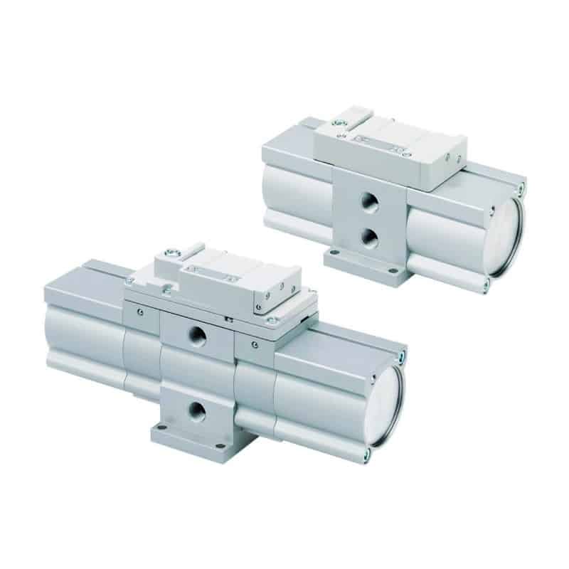
Inside a self-reciprocating booster regulator, inlet air powers a piston assembly and an internal directional mechanism. Part of the supply air drives the piston; another portion becomes the boosted outlet flow. When the piston reaches the end of its stroke, the internal valve reverses the drive path and the cycle repeats. Check valves maintain the outlet-side pressure between strokes.
The unit slows as outlet pressure approaches its equilibrium or stall condition. It does not create unlimited flow at the advertised maximum pressure. Open the manufacturer’s flow chart and find the intersection of actual inlet pressure and required outlet pressure. The available flow at that point is the number to compare with machine demand.
Two pressure ratios often get confused:
Thermodynamic compression ratio = Outlet absolute pressure / Inlet absolute pressure

Absolute pressure = Gauge pressure + local atmospheric pressure
For example, boosting from 6 bar(g) to 9 bar(g), using 1.013 bar atmospheric pressure, gives:
Compression ratio = (9 + 1.013) / (6 + 1.013) = 1.43That 1.43 value is useful for thermodynamic comparison. A catalog’s “2× pressure increase” may describe a model-specific gauge-pressure relationship at zero flow. Always use the definition and flow curve published for the selected series.
Do You Need a Booster or Should You Fix Pressure Drop First?
DOE says a properly designed compressed-air system should lose much less than 10% of compressor discharge pressure between the receiver and point of use. Near 100 psig, every additional 2 psi of compressor discharge can add about 1% full-output power, before artificial demand is included (DOE, 2003).
Measure before buying hardware. Log pressure at four points while the problem event occurs:
- the plant header near the branch connection
- upstream of the machine air-treatment assembly
- downstream of the filter and regulator
- at the actuator, clamp, or test device inlet
Use fast enough sampling to capture the actual pressure sag. A static gauge may show 6 bar before and after a cycle while missing a one-second drop to 4.8 bar during motion.
| Test result | Likely problem | First response |
|---|---|---|
| Header and machine inlet both sag | Plant capacity, controls, storage, or main distribution | Review compressor sequencing, leaks, main receiver, and header sizing |
| Header is stable but machine inlet sags | Branch restriction or insufficient local storage | Check pipe, hose, coupling, filter, dryer, regulator, and local receiver |
| Regulator inlet is stable but outlet sags | Regulator or FRL flow capacity | Compare the required flow with the component’s pressure-drop curve |
| Pressure remains stable but the cylinder is weak | Load, bore, friction, exhaust back pressure, or mechanical binding | Verify force and mechanical alignment |
| Only one small-volume device needs higher pressure | Legitimate local pressure requirement | Evaluate a booster regulator and high-pressure receiver |
In our experience, the decisive value in an application review is usually dynamic point-of-use pressure, not the compressor-room gauge. The pressure-drop troubleshooting guide explains how to isolate restrictions, while the pressure fluctuation guide covers short pressure sags and timing effects.
A booster is a poor repair for a clogged filter or undersized quick coupling. It is also a poor choice when a large continuous demand keeps the unit cycling at its limit. In those cases, fix the flow path, change the actuator or process, add appropriately sized storage, or review plant capacity.
How Do You Size a Booster for Pressure, Flow, and Storage?
SMC’s published sizing example calculates 146 L/min average demand and 877 L/min maximum instantaneous demand for one cylinder circuit. The catalog selects the booster from average flow, then requires an air tank when the booster’s available outlet flow is below the 877 L/min instantaneous peak (SMC, 2024).
Collect these inputs before selecting a model:
- minimum and maximum inlet pressure while the machine is operating
- required pressure at the consuming device, including its allowed pressure band
- average outlet flow over a complete operating cycle
- maximum instantaneous flow and event duration
- time available for the booster to recharge the receiver
- air temperature, air quality, ambient conditions, and permitted noise
- downstream component pressure ratings
Step 1: Confirm the pressure window
Check whether the required outlet pressure falls inside the model’s set range at the lowest inlet pressure. Then confirm the proof pressure, maximum operating pressure, gauge range, tubing, valves, fittings, actuator, and receiver all cover the proposed high-pressure side.
Step 2: Calculate average demand
Average demand determines whether the booster can recover over repeated cycles. For a cylinder, include both chamber volumes where applicable, switched tubing volume, pressure level, cycles per minute, and the number of devices operating. Use free-air or ANR units consistently.
Step 3: Calculate the instantaneous event
A fast clamp may demand much more flow during two seconds of motion than its shift average suggests. Compare that peak with the booster flow curve at the actual inlet and outlet pressures. Port size alone is not a flow rating.
Step 4: Size the high-pressure receiver
If peak demand exceeds booster output, a receiver supplies the difference while the booster continues running. A useful preliminary free-air relationship is:
Receiver volume = Atmospheric pressure × Net demand × Event time
                  / Allowed receiver pressure drop
Use absolute pressure consistently, keep time and flow units aligned, and apply the applicable pressure-vessel code. The air receiver sizing guide explains the full calculation; the Air Receiver Tank Sizing Calculator can estimate volume from demand flow, booster support flow, event duration, and the permitted pressure band.
From our analysis, a receiver separates the pressure problem from the flow problem. The booster establishes the high-pressure energy level over time; the receiver releases enough stored air to cover a short event. If average demand exceeds booster capacity, a larger receiver only postpones the pressure decline.
What Does a Pneumatic Booster Really Cost in Air?
SMC states that a 2× VBA consumes drive air equal to roughly 1.2 times the outlet volume, so inlet supply capacity must be about 2.2 times the delivered outlet volume. For its 4× version, the corresponding figures are approximately 3.7 and 4.7 times (SMC, 2024).
That is why a booster should serve the smallest practical high-pressure volume. Supplying one clamp at 9 bar can be sensible. Boosting an entire machine because one device was undersized usually is not.
Estimate total inlet demand as two parts:
Total inlet air = Delivered outlet air + Drive air consumed by the boosterDo not calculate cost from outlet volume multiplied by a generic pressure ratio. Use the selected model’s consumption data at the relevant inlet and outlet pressures, then add leakage, standby cycling, receiver losses, and production hours.
The following design choices often reduce high-pressure demand:
- use a larger cylinder bore at normal plant pressure when space and dynamics allow
- shorten high-pressure tubing and remove unnecessary dead volume
- keep valves and receivers close to the high-pressure device
- isolate the boosted branch instead of raising the full machine pressure
- repair downstream leaks that keep the booster cycling during dwell
- reduce the setpoint after measuring the minimum pressure that still completes the work reliably
DOE recommends reducing pressure drop and using strategic storage before increasing plant discharge pressure. That matters because raising the header also increases consumption through leaks and other unregulated uses. Compare the local booster with those alternatives using the compressed-air energy efficiency guide.
In our experience, the largest avoidable cost appears when a boosted branch remains pressurized through idle shifts and small downstream leaks keep the unit cycling. A simple isolation and leak test can reveal that loss before anyone changes the booster size.
Where Do High-Ratio Air Amplifiers and Gas Boosters Fit?
Haskel’s AA single-stage air amplifiers use 8:1, 15:1, and 30:1 ratios and list maximum outlet pressures from 2,500 to 4,500 psi. Its pneumatic gas-booster range reaches much higher model-specific pressures, but Haskel describes those units primarily for intermittent testing, charging, transfer, and laboratory duties (Haskel air amplifier, 2026; Haskel gas boosters, 2026).
An air amplifier uses part of the incoming compressed-air supply as drive air and pumps the balance to a higher pressure. A gas booster usually has a separate air-drive section and gas section, with dynamic seals and vented separation selected for the process gas.
For an area-ratio booster, a preliminary stall relationship may include both drive pressure and inlet-gas assistance:
Approximate stall pressure = Drive contribution + Inlet-gas contributionThe exact formula depends on the piston arrangement, number of stages, single- or double-acting construction, and manufacturer. Stall pressure is not a rated continuous-flow point. Flow falls as discharge pressure rises, and compression heating, seal speed, gas properties, cooling, and allowable compression ratio can become limiting factors.
Gas service requires a separate compatibility review. Oxygen needs oxygen-cleaned components and procedures. Hydrogen needs attention to leakage, ventilation, material compatibility, ignition control, and compression temperature. Nitrogen and other inert gases can create an asphyxiation hazard in enclosed spaces. Never substitute a general-purpose factory-air booster for a gas booster approved for the specified gas and pressure.
“No electric motor” also does not prove that an assembly is suitable for a hazardous location. Require the exact product documentation, system risk assessment, grounding and bonding provisions where applicable, and certifications required by the installation jurisdiction.
How Should You Install and Maintain a Booster Safely?
For U.S. air receivers, OSHA 29 CFR 1910.169 requires a visible pressure gauge and one or more spring-loaded safety valves. Their relieving capacity must prevent receiver pressure from exceeding its maximum allowable working pressure by more than 10%, and no valve may isolate the receiver from its safety valve (OSHA, 2026).
Local laws may require different pressure-vessel construction, registration, inspection, relief, drainage, or installation provisions. Apply the rules for the actual jurisdiction and receiver. ISO 4414:2010 remains the general machine-side pneumatic safety standard, but ISO states that it does not cover factory air-distribution systems, gas bottles, or receivers (ISO, 2026).
Use this installation checklist:
- Verify the maximum pressure rating of every downstream component.
- Install a correctly sized relief device on the high-pressure side.
- Provide visible pressure indication at the receiver and critical point of use.
- Route the booster exhaust where noise, cold exhaust air, and contamination will not create a hazard.
- Provide a method to isolate and exhaust downstream pressure before service.
- Keep the receiver drain accessible and manage condensate according to local requirements.
- Support piping so vibration and weight do not load the booster ports.
- Follow the manufacturer’s mounting orientation, filtration, temperature, and clearance instructions.
SMC warns that downstream pressure cannot be exhausted through the booster simply by venting its inlet because internal check valves retain pressure. Its operating manual shows a three-way valve on the outlet side for maintenance isolation and residual-pressure release (SMC operating manual, 2025).
Maintenance should be condition- and cycle-based, not a universal 6- or 12-month seal schedule. Watch for a booster that continues cycling with no downstream demand, shorter intervals between exhaust pulses, abnormal sliding noise, black contamination at the silencer, rising refill time, or unstable outlet pressure. SMC states that service life depends on air quality, operating pressure, and operating cycles.
Before servicing, isolate the energy sources, exhaust trapped downstream pressure, verify zero pressure, and follow the machine’s lockout procedure. Only trained personnel should disassemble a pressure booster.
Which Industrial Applications Actually Justify a Booster?
SMC offers factory-air booster regulator set-pressure ranges up to 2.0 MPa on selected VBA models, while Haskel’s air amplifiers begin around 2,500 psi maximum outlet pressure. That gap shows why an application must be matched to a device family and pressure class before “industrial pressure booster” is treated as one product category (SMC, 2026; Haskel, 2026).
A factory-air booster regulator is often justified when:
- one compact clamp needs more pressure than the plant header, and increasing bore size is impractical
- a small-volume press or staking operation has short, repeatable high-pressure events
- a test fixture needs a controlled pressure above the normal machine supply but within the booster’s rated range
- an existing machine has a legitimate local pressure requirement and the rest of the plant can remain at a lower efficient pressure
- a high-pressure receiver can recharge during dwell time
For instance, a compact clamp that needs two seconds of elevated pressure followed by a long assembly dwell is a better booster candidate than an open blow-off process that consumes high-pressure air continuously.
It is usually a weak solution when:
- pressure loss comes from clogged, undersized, or leaking components
- the required high-pressure flow is continuous and near the booster’s limit
- the process needs precise closed-loop pressure control beyond the selected unit’s capability
- a larger actuator at normal pressure is safer and more efficient
- high-pressure gas compatibility, cleanliness, or certification requirements exceed the equipment’s approval
Pressure and force must remain separate. A clamp requiring 20 kN does not automatically require “2,000 psi.” Calculate the force from effective area and pressure, include friction and load geometry, then decide whether a larger actuator or a higher-pressure circuit is the better machine design.
The best booster application is usually narrow: small high-pressure volume, short duty event, stable inlet supply, enough recharge time, and a clear reason the actuator cannot be resized. As the boosted volume and duty increase, the case for a different actuator or dedicated compressor becomes stronger.
What Should Go in a Booster RFQ?
SMC’s sizing method separates average flow from maximum instantaneous flow and checks tank need against the latter. A build-ready RFQ therefore needs at least two flow values plus the inlet and outlet pressure conditions; a request containing only “10 bar required” cannot establish recovery time, receiver size, or air consumption (SMC, 2024).
Send the supplier:
- medium: factory compressed air or named process gas
- minimum, normal, and maximum inlet pressure while flowing
- required outlet setpoint and minimum usable pressure at the device
- average outlet flow in a stated reference condition
- maximum instantaneous flow, event duration, and events per minute
- receiver high and low pressure, existing volume, and available recharge time
- operating hours, duty pattern, ambient and air temperature
- ISO 8573-1 air-quality class or actual particle, water, and oil limits
- port size, allowable pressure drop, installation envelope, and mounting orientation
- downstream component ratings and required relief arrangement
- hazardous-location, oxygen-cleaning, gas-compatibility, material, noise, and jurisdictional requirements
- expected maintenance access and isolation method
Include a cycle diagram when demand changes sharply during the machine sequence. It is more useful than one average CFM figure because it shows when the receiver discharges and how long the booster has to recover.
For a replacement, add the complete existing model code, nameplate photo, pressure settings, port arrangement, receiver details, recorded refill time, and the symptom that triggered replacement. Bepto Pneumatic can then review the operating point rather than matching only the thread size or body dimensions.
David Li’s compressed-air system role is listed on About Us. For model-specific corrections, application data, or a booster RFQ, use the contact page.
FAQs About Pneumatic Pressure Boosters
SMC’s mainstream factory-air boosters are generally 2× devices, with a 4× VBA11A option, while dedicated air amplifiers use much higher ratios. The answers below keep those product families separate and use pressure, flow, storage, and safety limits rather than treating one maximum ratio as universal (SMC, 2026).
Can a pneumatic booster turn 100 psi into 1,000 psi?
Not every booster can. A standard factory-air booster regulator is commonly limited to about 2× inlet pressure, with some models offering 4×. Reaching 1,000 psi from 100 psi requires a high-ratio air amplifier or gas booster rated for the medium, pressure, flow, temperature, and duty—not a generic FRL-style booster regulator.
Does a booster maintain its rated pressure at any flow?
No. The headline ratio is commonly a zero-flow or stall relationship. Outlet pressure falls or the booster cycles faster as demand rises. Select from the manufacturer’s flow curve at the actual inlet and outlet pressures, then use a receiver when short peak demand exceeds the available booster flow.
How much inlet air does a 2× booster require?
For SMC’s VBA example, drive-air consumption is approximately 1.2 times the outlet volume at a 2× pressure increase, making the required inlet supply capacity about 2.2 times delivered outlet volume. Use the exact model data; leakage, standby cycling, and operating pressure can increase actual consumption.
Can I use a receiver to make an undersized booster work?
A receiver can cover a short peak when the booster has enough average capacity and enough time to recharge between events. It cannot correct a permanent average-flow deficit. Log the demand profile, subtract booster support during the event, and size the receiver from the permitted pressure band.
How often should booster seals be replaced?
There is no universal replacement interval. SMC says life depends on air quality, pressure, and operating cycles. Track refill time, unwanted cycling at zero demand, leakage, exhaust-pulse interval, noise, and silencer contamination. Follow the exact model’s inspection and maintenance manual rather than replacing seals on a generic calendar.
Are air-driven boosters automatically explosion-proof?
No. The absence of an electric motor removes one potential ignition source, but it does not certify the complete booster package for a hazardous location. Verify the exact product approvals, process gas, materials, exhaust, static control, ventilation, temperature, and area-classification requirements with the manufacturer and site safety authority.
Sources
-
SMC VBA/VBAT Series Catalog, pressure increase, flow selection, air consumption, and tank-sizing example. Retrieved 2026-07-17.
-
SMC VBA Web Catalog, product pressure ratios and set-pressure ranges. Retrieved 2026-07-17.
-
SMC VBA Operating Manual, installation, residual-pressure release, operating limits, troubleshooting, and maintenance indicators. Retrieved 2026-07-17.
-
DOE: Improving Compressed Air System Performance, pressure drop, system pressure, artificial demand, and strategic storage. Retrieved 2026-07-17.
-
Haskel AA Series Air Amplifiers, high-ratio air-amplifier mechanism, ratios, outlet limits, and air-volume accounting. Retrieved 2026-07-17.
-
Haskel Pneumatic-Driven Gas Boosters, gas-booster applications, pressure limits, gas service, and intermittent duty context. Retrieved 2026-07-17.
-
OSHA 29 CFR 1910.169: Air Receivers, receiver gauges, drains, safety valves, accessibility, and relief requirements. Retrieved 2026-07-17.
-
ISO 4414:2010, general pneumatic-system safety requirements and scope limits. Retrieved 2026-07-17.