

A pneumatic pressure booster can avoid a separate high-pressure compressor or hydraulic power unit when one local, intermittent load needs more pressure than the plant header provides. It is not free energy: the booster sacrifices inlet-air volume and flow to create higher outlet pressure. The right decision therefore depends on pressure, peak flow, duty cycle, storage, downstream ratings, and a site-specific cost comparison.
If the whole plant is short of pressure, or the demand is continuous and high-volume, a local booster may become an expensive way to hide an upstream problem. Measure dynamic pressure first and correct restrictions before selecting another pressure-producing device.
Key Takeaways
- A factory-air booster regulator, an air amplifier, and a gas booster are different product classes.
- Select from both average demand and maximum instantaneous demand; pressure ratio alone is not a size.
- A receiver can cover a short peak only if the booster can recharge it before the next event.
- Higher outlet pressure increases drive-air demand and stored-energy risk.
- Savings must be calculated against the real alternatives, not assumed from a universal percentage.
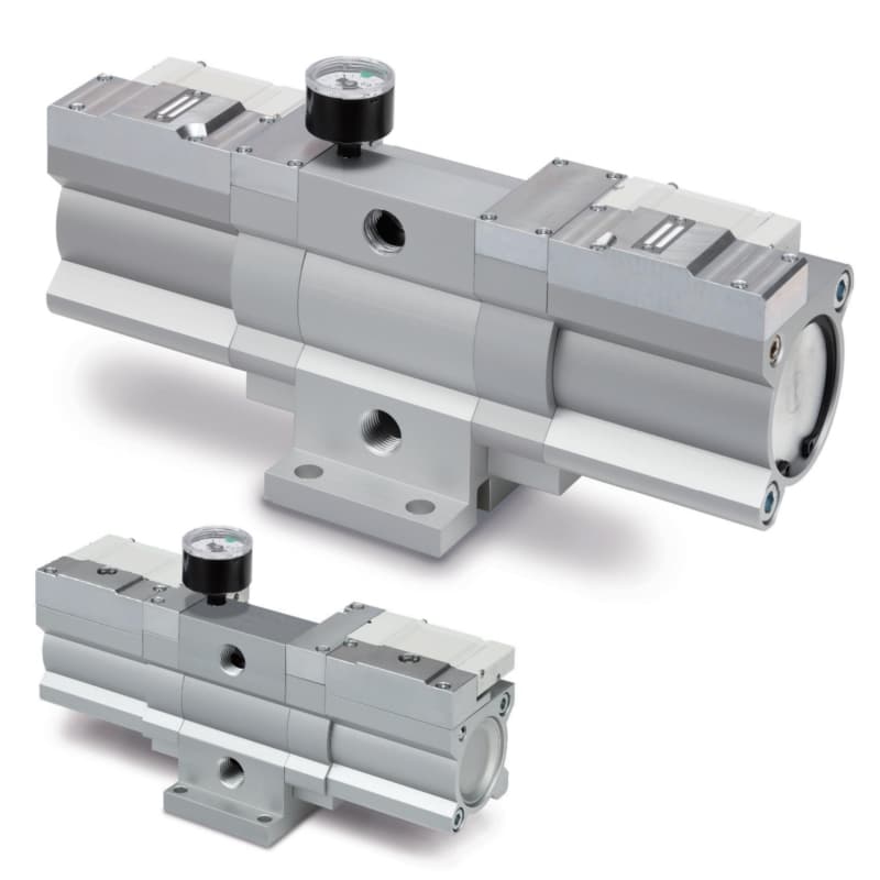
A low-air-consumption booster regulator is intended for localized factory-air service. Its exact pressure range, flow curve, air consumption, and permitted duty come from the model data sheet.
First, Identify Which Kind of Booster You Actually Need
The phrase “pressure booster” covers devices with very different ratios, media, flow capacities, and safety requirements. A factory-air booster regulator is an air-driven device that raises compressed-air pressure for a bounded downstream zone. Do not place a 2-times factory-air regulator and a 30:1 high-pressure air amplifier in one generic performance table.
| Device class | Typical engineering role | Example published range | Main selection caution |
|---|---|---|---|
| Factory-air booster regulator | Raises pressure for a local cylinder, clamp, test step, or air tool | SMC VBA families include 2-times models and a 4-times model; one current VBA10A/11A variant lists 0.4 to 1.4 MPa and 0.8 to 2.0 MPa outlet ranges respectively | Flow falls as the required pressure increase rises; drive air is exhausted |
| Air pressure amplifier | Produces much higher compressed-air pressure at lower displacement per cycle | Haskel AA single-stage models are published at 8:1, 15:1, and 30:1, with model-specific maximum outlets from 2,250 to 4,500 psig | Maximum ratio is not usable flow, and the system must be rated for the possible stall pressure |
| Pneumatically driven gas booster | Compresses a specified process gas using a separate air-drive section | Ratio, wetted materials, leakage class, contamination limits, and outlet rating are application-specific | Oxygen, hydrogen, nitrogen, refrigerant, and breathing-air service cannot be treated as ordinary plant-air service |
| Air-to-oil intensifier | Converts pneumatic input into a limited high-pressure hydraulic volume | Pressure depends on area ratio and usable oil displacement | It introduces hydraulic fluid and a finite power-stroke volume; it is not an air booster |
The SMC figures above come from its VBA/VBAT catalog and VBA10A/11A product sheet. The high-ratio examples come from the Haskel AA Series page. These are product examples, not universal limits.
For most automated-machinery questions, start with a factory-air booster regulator. Move to an air amplifier only when the required pressure, delivered volume, medium, and component ratings clearly place the application in that class.
How Does a Pneumatic Booster Regulator Increase Pressure?
A booster regulator uses compressed air on connected piston areas to create a net force that compresses outlet air. Check valves direct the boosted air downstream. At the end of a stroke, an internal switching valve reverses the assembly, so the two sides alternately fill, boost, and exhaust. A governor or regulator section stops cycling as the outlet approaches its set pressure. When downstream demand lowers the pressure, cycling resumes.
This explains four behaviors that matter during selection:
- The unit stalls near its pressure balance. A nominal ratio describes the pressure relationship near low or zero outlet flow; it does not promise full catalog flow at that pressure.
- Useful flow depends on the operating point. Read the manufacturer’s curve at the actual inlet pressure and required outlet pressure.
- Drive air is consumed. Some inlet air becomes delivered high-pressure air, while another portion powers the piston and exhausts to atmosphere.
- Operation is cyclic. Pulsation, exhaust noise, recharge time, and life depend on how frequently and how far the piston travels.
Pressure-increase ratio is not always the same as absolute compression ratio
Manufacturers often describe a booster as “2 times” or “4 times” using their stated pressure-increase convention. Thermodynamic compression ratio uses absolute pressure:
Absolute compression ratio = outlet absolute pressure / inlet absolute pressure

CR = P2(abs) / P1(abs)
For example, increasing air from 0.5 MPa(g) to 1.0 MPa(g) is a 2-times increase in gauge-pressure terms. Using standard atmospheric pressure of about 0.1013 MPa, its absolute compression ratio is approximately:
CR = (1.0 + 0.1013) / (0.5 + 0.1013) = 1.83That distinction prevents mistakes when compressor, temperature, or energy calculations expect absolute values. The absolute-pressure guide explains the reference, while the calculator below checks the conversion.
When Can a Booster Reduce Equipment and Infrastructure Cost?
The strongest use case is a small, bounded pressure zone whose peak demand is separated by enough idle time for recharge. Examples include a high-force clamp, a short press step, a leak-test station, a crimping head, a mold-support function, or one actuator that cannot be enlarged because of space. In our experience, this boundary matters more than the headline ratio.
A booster can remove cost from a project when it avoids one or more of these alternatives:
- Raising the pressure of the entire plant header for one machine.
- Installing a separate high-pressure compressor and distribution branch.
- Adding an electric or hydraulic power unit, tank, cooling, controls, and fluid-management work.
- Rebuilding a compact machine around a larger cylinder.
However, the booster adds its own purchase price, inlet-air consumption, exhaust treatment, receiver, valves, gauges, relief provisions, and maintenance. A defensible comparison uses the same pressure, delivered flow, annual production, availability target, and safety boundary for every option.
| Cost item | What to compare over the chosen service period |
|---|---|
| Capital | Booster or compressor, receiver, relief hardware, controls, piping, guards, installation, validation |
| Energy | Measured or catalog inlet-air requirement at the real operating point, compressor specific power, annual cycles |
| Maintenance | Filters, seals, silencers, inspections, pressure-vessel obligations, specialist service |
| Production risk | Recharge delay, pressure decay, single-point failure, spare availability, recovery time |
| Process impact | Force repeatability, cleanliness, heat, noise, leakage, product-change flexibility |
The economic boundary should be drawn around the pressure zone, not the individual booster. A low purchase price is irrelevant if an undersized upstream branch, receiver, or relief system must later be replaced to make it work.
Before buying, compare the booster option with correcting dynamic pressure drop, increasing actuator area, reducing mechanical loss, or changing the process sequence. A booster cannot restore flow lost through a clogged filter, narrow tube, undersized valve, or restricted exhaust.
Consider a machine with one clamp that needs a brief high-pressure pulse every 20 seconds while every other actuator works at normal header pressure. A local booster and receiver may be reasonable because the high-pressure zone is small and the receiver has time to recharge. Now consider the same outlet pressure feeding a continuous blow-off process. Its average demand approaches its peak demand, so the booster may run almost continuously and consume far more drive air. A dedicated source, process redesign, or lower-flow nozzle may be more defensible. Our team found that comparing event volume, event time, and recovery time eliminates many unsuitable booster selections before model numbers enter the discussion. The example does not set a universal duty limit; the selected product’s flow curve, charge curve, life data, and environmental limits still control.
How Do You Size Pressure, Flow, and Receiver Capacity?
Start with a time-based demand profile. A statement such as “we need 1 MPa” is incomplete because a closed receiver can reach the target slowly while the same booster fails to sustain it during a 0.4-second stroke.
1. Define the pressure window at the load
Record:
- Minimum acceptable pressure at the actuator or process during maximum demand.
- Maximum permitted normal pressure.
- Possible maximum or stall pressure in every operating and fault state.
- Upstream pressure range while neighboring machines are running.
- Pressure loss through the filter, valve, tubing, fittings, and exhaust path.
If pressure exists mainly to create cylinder force, calculate from the lower dynamic pressure, effective piston area, opposing pressure, friction, acceleration, and design margin. The cylinder bore and air-consumption guide shows why a larger bore changes both force and demand.
2. Separate average demand from instantaneous demand
Convert cylinder chambers, connected piping, and other consumers to the same referenced free-air basis used in the catalog, such as L/min (ANR). Then determine:
- Average demand: air per complete operating cycle multiplied by cycles per minute.
- Maximum instantaneous demand means the air required during the shortest high-flow event divided by that event time.
SMC’s VBA selection example illustrates the gap. For its defined 100 mm-bore, 100 mm-stroke cylinder duty, the catalog calculates 146 L/min (ANR) average demand but 877 L/min (ANR) maximum instantaneous demand. The example is not a shortcut for other machines; it shows why an average-only selection can look adequate and still suffer a pressure collapse during the stroke.
3. Read the model flow curve at the operating pressures
Do not use a catalog’s largest headline flow. Find the curve or table for the actual inlet and outlet pressures. The model must at least support the average requirement. If its outlet flow at that point is below the instantaneous requirement, storage or a larger booster is needed.
Also size the inlet branch. SMC states that its conventional VBA booster consumes drive air approximately 1.2 times the delivered outlet-side volume at a 2-times pressure increase and approximately 3.7 times at 4 times. Including delivered air, the required inlet supply capacity is approximately 2.2 and 4.7 times the outlet-side volume, respectively. Those values are specific to that catalog family, but they reveal the direction of the tradeoff: more pressure multiplication requires substantially more inlet capacity.
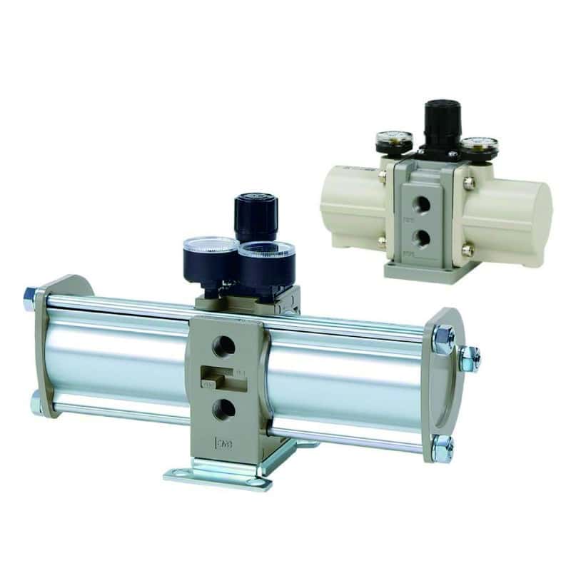
A booster assembly needs room for gauges, silencers, isolation, downstream pressure release, service access, and, where required, a correctly rated receiver.
4. Add a receiver only when it closes the peak-flow gap
Usable receiver storage is the air available between the permitted upper and lower receiver pressures. It can supply the difference between load demand and booster output during a short event. Nominal liters alone do not define that capacity. The booster must then refill the volume within the available stop time.
Use this sequence:
- Define receiver upper pressure and the minimum pressure that still protects the process.
- Calculate the air deficit during the peak event on a consistent absolute-pressure and reference-volume basis.
- Select a receiver whose usable volume covers that deficit with margin.
- Check the booster charge curve and verify recharge before the next demand.
- Confirm vessel rating, relief arrangement, drains, inspection access, and local regulatory obligations.
The Air Receiver Tank Sizing Calculator is useful for a first-pass short-demand estimate. Final selection must use the booster manufacturer’s method because booster output changes with pressure and continues during part of the discharge event.
5. Check duty and life at the proposed operating point
Count expected piston cycles or use the manufacturer’s sizing software. SMC explicitly warns that long continuous operation requires a life-expectancy check and may require a larger unit. A calendar statement such as “replace seals every two years” cannot be generalized across models, stroke utilization, contamination, pressure, and cycle rate.
From our analysis of manufacturer selection workflows, the missing input is usually not pressure; it is the timing trace. A simple record of inlet pressure, outlet pressure, machine state, and cycle interval often determines whether the answer is a larger booster, a receiver, a larger supply line, or no booster at all.
When Is a Pneumatic Booster the Wrong Solution?
A booster is usually a poor first choice in these conditions:
- Plant-wide low pressure: diagnose compressor controls, dryers, filters, leaks, headers, and distribution before multiplying pressure locally.
- Continuous high-volume demand: the unit may cycle almost constantly, consume large quantities of drive air, and struggle to meet life or noise targets.
- A flow restriction is the real fault: static pressure may be acceptable while dynamic pressure collapses across an undersized component.
- The actuator can be enlarged safely: more effective area may provide the force at normal plant pressure with lower system complexity.
- The process needs tightly controlled dynamic pressure: review a suitably sized regulator or electro-pneumatic proportional regulator and feedback loop; a booster supplies pressure capacity but does not replace process control.
- The medium is hazardous or purity-critical: use a booster designed, cleaned, documented, and approved for that exact gas and service.
- No safe outlet-energy strategy exists: do not install the booster until overpressure, isolation, residual pressure, hose failure, and maintenance access are resolved.
Raising plant pressure is not an automatic alternative. The U.S. Department of Energy’s compressed-air systems resource lists guidance on low-pressure end uses, storage, pressure stabilization, inappropriate uses, and end-use efficiency. The engineering choice is therefore often between a corrected low-pressure system plus a small local boost zone and a justified separate high-pressure source.
What Safety and Integration Details Belong in the Design?
Boosted air stores more energy and can expose downstream parts to pressures they never saw on the original header. Treat the complete outlet zone as a higher-pressure system.
At minimum, document:
- Maximum possible outlet or stall pressure, including high inlet pressure and control faults.
- Pressure ratings for the receiver, valve, regulator, gauges, sensors, fittings, tube, hoses, silencers, and actuator.
- A relief or limiting strategy sized and located for the credible overpressure case.
- Inlet isolation, downstream isolation, and a verified method to release trapped outlet pressure.
- Check-valve and backflow behavior during supply loss.
- Safe machine response if boosted pressure falls, rises, or cannot recharge in time.
- Exhaust routing, noise, icing or condensation risk, and contamination control.
- Guards or separation for high-pressure hoses and components.
- Local pressure-vessel, inspection, electrical-area, and machinery requirements.
The SMC VBA/VBAT catalog instructs designers to provide measures against abnormal outlet pressure and to use a downstream 3-port valve when outlet residual pressure must be released quickly. Follow the exact manufacturer’s instructions for the chosen model.
ISO 4414:2010, confirmed current by ISO in 2021, gives general safety requirements for pneumatic fluid-power systems and components. Its scope excludes compressors, factory air-distribution systems, and gas bottles and receivers, so it cannot by itself establish receiver compliance. Apply the relevant vessel and machinery rules in the installation jurisdiction.
Before servicing, isolate energy and make stored or residual pressure safe. In the United States, OSHA 29 CFR 1910.147 addresses servicing where unexpected energization or release of stored energy could injure personnel. Site procedures and applicable law control the actual lockout method.
How Should You Commission and Maintain the Booster?
Commissioning should prove the pressure zone under normal production and credible faults, not merely show that a gauge rises with the outlet blocked.
Commissioning checklist
- Verify model, flow direction, mounting, port size, permitted medium, temperature, lubrication policy, and silencer arrangement.
- Flush new piping using the approved procedure before connecting the unit.
- Confirm all downstream pressure ratings and the relief-setting basis.
- Pressurize in the manufacturer’s sequence and set the outlet within its allowed range.
- Record inlet and outlet pressure at no flow, normal flow, and maximum repeatable demand.
- Measure time from the receiver’s lower limit to upper limit and compare it with available idle time.
- Confirm that the safety circuit detects unacceptable pressure and drives the machine to its defined safe state.
- Check leakage, exhaust noise, vibration, temperature, condensate, and hose restraint.
- Save the baseline pressure trace, cycle count, settings, and acceptance results.
Condition-based maintenance
Use the product manual and the risk of the pressure zone to set inspection intervals. Useful condition indicators include:
- Longer recharge time under the same inlet and demand conditions.
- Lower outlet pressure during a repeatable event.
- Higher cycling frequency with no production change.
- External leakage or unexpected exhaust while the system should be at rest.
- Abnormal impact noise, vibration, heat, frosting, or silencer restriction.
- Filter differential pressure, condensate, or contamination outside the specified air-quality limit.
- Relief-device, gauge, sensor, hose, and receiver inspection results.
Do not add an airline lubricator unless the exact product requires it. One current SMC VBA10A/11A sheet specifies grease lubrication and non-lube operation; other designs may differ. Use approved service kits and instructions, then repeat the commissioning acceptance test after maintenance.
What Information Should Be Sent in a Booster RFQ?
A useful request for quotation makes the duty reproducible:
| RFQ field | Required information |
|---|---|
| Medium | Compressed air or named gas, purity, particle/oil/water limits, inlet temperature |
| Inlet | Minimum and maximum pressure at the booster during real demand; available free-air flow |
| Outlet | Normal setpoint, minimum dynamic pressure, maximum permitted pressure, possible stall pressure |
| Demand | Volume per event, event duration, cycles per minute, simultaneous consumers, leakage allowance |
| Receiver | Existing volume and rating, permitted high/low pressure, available recharge time |
| Installation | Port and tube sizes, distance to load, orientation, ambient conditions, hazardous area |
| Controls | Pressure sensors, alarms, PLC signals, isolation and dump sequence, safe state |
| Compliance | Jurisdiction, machine standard, vessel rules, documentation and test certificates |
| Commercial | Annual hours and cycles, required life, service access, spares, downtime target |
That information lets suppliers compare the requested operating point with a flow curve, charge curve, duty limit, and downstream pressure boundary. “90 psi in, 180 psi out” does not.
FAQs About Pneumatic Pressure Boosters
Can a pneumatic booster double pressure without consuming extra air?
No. An air-driven booster consumes compressed air to operate its piston and switching mechanism. In SMC’s conventional VBA catalog, the approximate inlet supply capacity is 2.2 times the delivered outlet-side volume for a 2-times model and 4.7 times for a 4-times model. Use the figures for the exact model and operating point.
Does a 2:1 booster deliver full flow at twice the inlet pressure?
No. The nominal ratio describes pressure capability, usually near stall or low-flow conditions. Available outlet flow depends on inlet pressure, outlet pressure, model size, and the manufacturer’s flow curve. Pressure approaches the limit as usable flow approaches zero.
Do I always need an air receiver after a pressure booster?
No. If booster output at the real operating point equals or exceeds maximum instantaneous demand, a receiver may not be necessary. If the booster meets average demand but not the peak, a correctly sized receiver can bridge the difference only when there is enough time to recharge it.
Can a booster increase force on an existing pneumatic cylinder?
Yes, if the cylinder and every downstream component are rated for the higher pressure and the delivered dynamic pressure remains high enough during motion. Recalculate force, air consumption, cushioning, structural loads, and failure behavior. Higher static pressure alone does not prove the system can provide the required flow.
How often should a pneumatic pressure booster be serviced?
There is no universal monthly or annual interval. Use the manufacturer’s instructions, expected piston cycles, pressure, air quality, environment, duty, failure consequence, and as-found history. Track recharge time, pressure under a repeatable load, leakage, cycling behavior, filter condition, and safety-device checks so the interval is based on evidence.
A pneumatic pressure booster transforms an operation only when it is treated as a complete pressure zone. Define the medium, pressure window, demand trace, receiver behavior, ratings, safe state, and lifetime cost. When those checks favor a local booster, it can be a compact alternative to raising an entire plant header or adding a separate power system. When they do not, the same analysis points to the restriction, actuator, compressor, or process change that should be addressed instead. Learn more about our pneumatic application background, or contact us with the completed RFQ fields for a model review.
External technical references and retrieval dates
- SMC, VBA/VBAT Series catalog. Working principle, selection sequence, average and maximum instantaneous flow, air consumption, receiver requirement, duty, abnormal-pressure, and residual-pressure guidance. Retrieved 2026-07-17.
- SMC, VBA10A/11A Booster Regulator product sheet. Model-specific ratios, flow, pressure ranges, temperature, lubrication, and worked receiver example. Retrieved 2026-07-17.
- SMC Video Library, Low Air Consumption Booster Regulator VBAE. Official source page for the embedded product animation. Retrieved 2026-07-17.
- Haskel, AA Series Single Acting, Single Stage Air Amplifier. Model-specific air-amplifier ratios, pressure limits, displacement, and stall formulas. Retrieved 2026-07-17.
- ISO 4414:2010. Scope and general pneumatic fluid-power safety requirements; confirmed current in 2021. Retrieved 2026-07-17.
- OSHA 29 CFR 1910.147. Control of hazardous energy during servicing. Retrieved 2026-07-17.
- U.S. Department of Energy, Compressed Air Systems. Current DOE tools and publications for low-pressure end uses, system analysis, storage, controls, pressure stabilization, inappropriate-use removal, and end-use efficiency. Retrieved 2026-07-17.