


Integrating feedback sensors with pneumatic actuators can replace assumed motion with measured position. It does not automatically create precision. The machine gains useful control only when the sensor measures the correct datum and the controller reads the signal fast enough. The valve must also correct motion, and the loaded axis must pass a defined acceptance test.
That boundary matters. A magnetic switch can confirm an endpoint. A position transmitter can report displacement. A servo pneumatic axis also needs a proportional valve and position controller. Treating those three levels as interchangeable leads to wrong hardware and unsupported accuracy claims.
Key Takeaways
- One SICK MPS-G model lists 0.01 mm resolution but 0.3 mm typical linearity error.
- A switch confirms state; a transmitter measures position; a closed loop corrects motion.
- Specify the datum, signal, update time, load, valve, air conditions, and acceptance test together.
- Sensor resolution alone is never machine accuracy.
What Does Sensor Integration Actually Change?
Festo’s SDAT-MHS position transmitter offers five sensing ranges from 50 to 160 mm and outputs of 0-10 V, 4-20 mA, or IO-Link (Festo SDAT-MHS, 2024). Those interfaces let a controller observe piston movement instead of inferring it from a valve command or timer.
Pneumatic actuator feedback is a measured electrical signal that represents a physical state of the actuator or driven mechanism. That state may be an endpoint, a position window, continuous displacement, chamber pressure, or another process variable. The signal becomes useful only after the controller scales it, checks its validity, and connects it to machine logic.
This creates three distinct control levels:
| Level | What the sensor reports | What the controller can prove | What it cannot do alone |
|---|---|---|---|
| Discrete confirmation | On/off state at an endpoint or zone | Arrival, departure, timeout, sequence interlock | Cannot measure continuous position or reliably identify intermediate states during motion. |
| Continuous measurement | Analog or digital position value | Actual position, window, trend, rate of change | Cannot correct motion without a variable output and position loop. |
| Closed-loop motion | Position plus controller and variable valve | Compare target with actual position and apply correction | Cannot remove mechanical compliance, air compressibility, friction, or load disturbance by itself. |
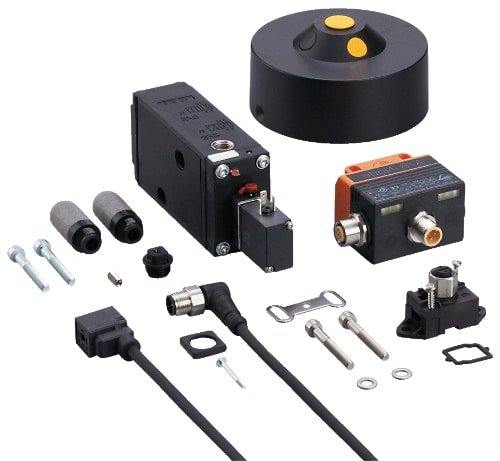
The first design question is not “Which sensor is most accurate?” Ask what the machine must prove. A clamp may need one reliable end signal. A gripper may need three object states. A long-stroke carriage may need measured position. A recipe-driven axis may need closed-loop control.
For a fuller comparison of reed switches, LVDTs, magnetostrictive sensors, and encoders, use the separate pneumatic cylinder position sensing guide. This article focuses on the integration work after the sensing level is chosen.
Integration Boundary: Sense the Process Datum
SICK specifies a 50 mm detection zone for one MPS-G analog cylinder sensor and warns that deviations are possible depending on the drive (SICK MPS-G instructions, 2025). The warning captures the integration problem: piston position and process position are not always the same.
The process datum is the physical feature whose location determines whether the operation succeeded. It may be the piston, rod end, rodless-cylinder carriage, guided slide, gripper jaw, clamp face, or tooling plate. Mount the sensor so its measurement follows that datum closely enough for the required decision.
A piston magnet can move while an external coupling slips. A carriage encoder can report motion while the tooling bracket flexes. An end switch can turn on before a soft part is fully clamped. None of these signals is wrong. Each is measuring a different physical point.
Build the feedback boundary from the workpiece backward:
- Define the process result, such as “tooling plate inside a 0.8 mm window under load.”
- Identify the mechanical datum that represents that result.
- List every compliant or loose element between the sensor and that datum.
- Decide whether the PLC needs a state, a measured position, or active motion correction.
- Select the lowest-complexity sensor that proves the required state.
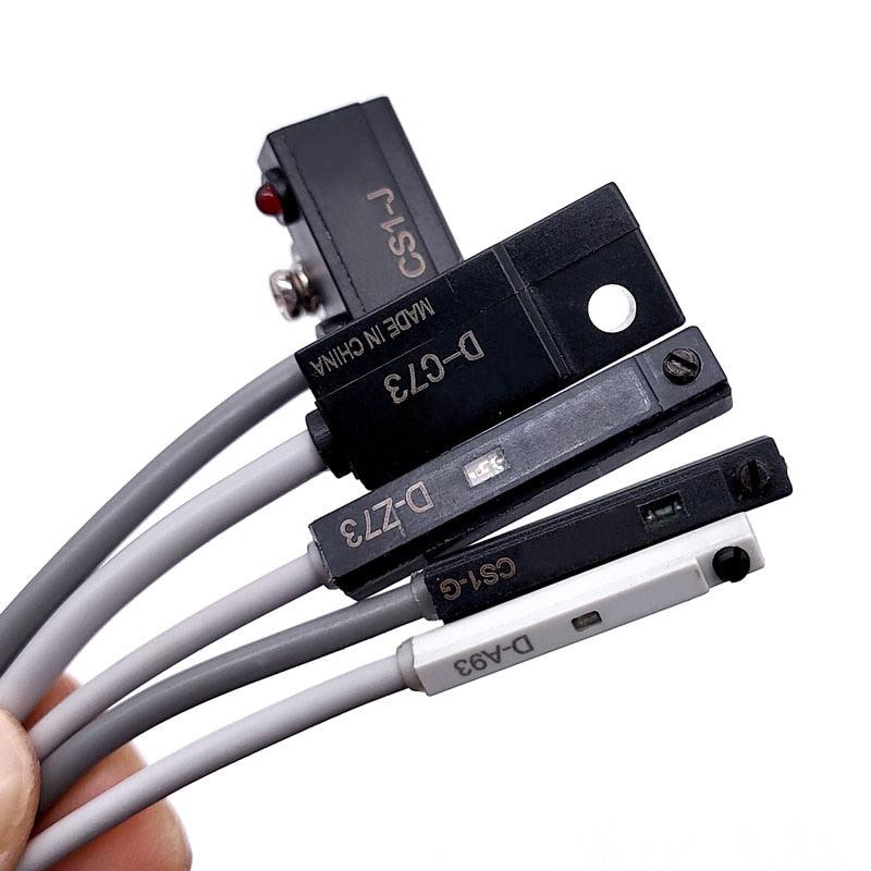
Endpoint switches remain the right answer for many two-position actuators. They are simple, fast to diagnose, and easy to interlock. Continuous feedback is justified when the process needs a measured position, several adjustable windows, displacement trending, or an actual-value input for a control loop.
How Should You Connect Feedback to the Controller?
The Festo SDAT-MHS datasheet lists a 1 ms minimum IO-Link cycle time, 12-bit position process data, and a 1 kHz maximum switching frequency (Festo SDAT-MHS, 2024). These are device specifications, not guaranteed machine response, but they show why interface timing belongs in the controls design.
Start with the controller input, not the cable color. Confirm supply voltage, PNP or NPN logic, normally open or normally closed behavior, analog range, input resolution, scan or motion-task period, connector pinout, diagnostic bits, and the safe value for a broken wire.
| Signal type | Controller requirement | Strong fit | Integration risk |
|---|---|---|---|
| PNP/NPN discrete | Matching digital input and common | Endpoint, zone, interlock | Wrong polarity, bounce, or a missed pulse. |
| 0-10 V analog | Voltage input with correct range and grounding | Short cable, position trend, window logic | Ground offset or electrical noise. |
| 4-20 mA analog | Current input and loop supply | Longer industrial runs and wire-break detection | Scaling, loop resistance, or common error. |
| IO-Link | Compatible master, IODD, process-data mapping | Position plus configuration and diagnostics | Risks include the wrong port mode, cycle time, or byte mapping. |
| Encoder or absolute interface | High-speed or motion input | External carriage or tooling position | Risks include misalignment, count loss, homing error, and slow updates. |
Analog scaling must preserve engineering units. If 4 mA represents 0 mm and 20 mA represents 160 mm, the program should convert the raw input to millimeters, set plausible limits, and alarm on an out-of-range value. Store both the raw value and scaled value during commissioning. That makes wiring faults easier to separate from mechanical faults.
Cable routing matters too. Keep low-level analog or encoder wiring away from solenoid coils, variable-frequency-drive cables, weld circuits, and high-current switching. Use the sensor manufacturer’s grounding and shielding instructions. For moving cables, define bend radius, strain relief, connector orientation, and drag-chain duty alongside the pneumatic tubing route.
When Does Feedback Become Closed-Loop Control?
Festo defines a servo pneumatic positioning system as three principal elements: a cylinder with displacement encoder, a proportional directional valve, and a position controller (Festo Servo-Pneumatic Positioning, 2026). Feedback alone monitors motion; the loop closes only when the controller changes an output from the measured error.
Closed-loop position control means the controller repeatedly compares the target position with measured position and adjusts the valve command to reduce the error. A PLC that logs an analog sensor but still drives a standard extend/retract valve is monitored open-loop control, even if the screen displays position to three decimal places.
The complete loop contains:
- Target position or motion profile
- Position controller and error calculation
- Variable valve command
- Proportional directional valve
- Pneumatic actuator and load
- Feedback sensor at the correct datum
- In-position, timeout, and fault logic
Festo lists 100 to 2,000 L/min flow options for its MPYE proportional directional valve family (Festo Proportional Directional Valves, 2026). That range is another reminder that valve capacity must match bore, stroke, target time, tubing, and pressure. A fine sensor cannot compensate for a valve that cannot fill or exhaust the chambers fast enough.
When target stroke time is known, estimate the required air demand with the Cylinder Flow Requirement Calculator. Treat the result as valve and tubing pre-selection. Final tuning still depends on real point-of-use pressure, exhaust restriction, load, friction, and controller behavior.
The dedicated servo pneumatic positioning guide covers valve and controller selection in more depth. Keep the boundary clear: the sensor supplies an actual value, but system architecture determines whether that value changes motion.
Why Does Position Accuracy Need an Error Budget?
One SICK MPS-G analog model lists 0.01 mm typical resolution, 0.05 mm typical repeatability, and 0.3 mm typical linearity error at stated conditions (SICK MPS-G instructions, 2025). The three numbers describe different properties, and none equals finished-machine accuracy.
Resolution is the smallest change the sensor can distinguish. Repeatability describes the spread when the same condition is measured repeatedly. Linearity error describes deviation from the ideal response across the measuring range. Machine positioning also includes mounting, guide, load, valve, pressure, temperature, controller, and measurement uncertainty.
Use an error budget to expose those contributors before promising a tolerance:
| Contributor | What to verify | Typical evidence |
|---|---|---|
| Sensor | Resolution, repeatability, linearity, range, update time | Use the exact part-number datasheet. |
| Mounting and datum | Bracket movement, alignment, magnet path, cable force | Inspect and make a static comparison. |
| Mechanics | Guide clearance, frame flex, coupling slip, seal friction | Check with a dial indicator or independent reference under load. |
| Pneumatics | Moving pressure, valve deadband, tube volume, exhaust restriction | Review pressure and command trends. |
| Controls | Input conversion, scan time, filter delay, tuning, in-position logic | Log raw and scaled signals. |
| Process | Load, speed, direction, dwell, temperature, product contact | Run a loaded acceptance test. |
Do not add every datasheet maximum and call the sum “accuracy” without understanding how the errors combine. Some terms are systematic, some vary with direction, and some appear only under motion. A conservative screening total can help early design, but the acceptance test must measure the assembled axis.
NIST explains that different internal characterization methods have caused ambiguity when positioning performance is compared, which is why terminology and test conditions matter (NIST Single-Axis Positioning Methods, 2013). State accuracy, repeatability, bidirectional behavior, load, travel, speed, environment, and measurement uncertainty separately.
How Should You Commission and Verify the Axis?
ASME B5.64 for single-axis linear positioning systems was first published in 2023, and NIST describes its purpose as guidance for specifying and testing positioning performance (NIST AIMS, 2026). A pneumatic integration does not need metrology-lab complexity, but it does need a repeatable acceptance method.
Commission in layers so one fault cannot hide behind another:
- Electrical check: verify part number, supply, pinout, input type, shield, raw counts, and broken-wire behavior.
- Static position check: move slowly through the range and compare the sensor with an independent reference at several points.
- Direction check: approach the same target from both directions to expose backlash, hysteresis, and seal effects.
- Dynamic check: run at production speed and log target, actual position, valve command, chamber or supply pressure, and in-position state.
After those four checks establish a trustworthy signal chain, verify the application envelope and the machine’s defined response to abnormal conditions:
- Load check: repeat with minimum, nominal, and worst-case payload or process force.
- Disturbance check: vary approved supply pressure and temperature conditions, then observe recovery.
- Fault check: disconnect the sensor, force an implausible value, interrupt air, and verify the machine reaches its defined safe state.
- Recovery check: test startup, air restoration, emergency-stop recovery, and recipe change.
In our experience, the most useful commissioning plot has four traces: target position, measured position, valve command, and point-of-use pressure. Position error without valve command hides tuning behavior. Position error without dynamic pressure can make an air-supply restriction look like a sensor fault.
Define the pass condition before the test. “Accurate positioning” is not measurable. “Reach 420.0 mm within +/-0.8 mm in 0.9 seconds, carrying 12 kg, from both directions, for 100 cycles” is measurable. The numbers must come from the real process requirement, not from a generic sensor table.
If the measured position arrives late, compare it with the solenoid valve response-time guide and the pressure-drop troubleshooting guide. Sensor delay is only one part of total machine response.
Fault Logic Must Distrust Impossible Feedback
SICK’s IO-Link MPS-G instructions describe up to 16 switching points plus diagnostic data such as temperature, orientation, vibration, and maximum acceleration (SICK MPS-G IO-Link, 2025). More data improves diagnosis only when the program defines valid and invalid states.
At minimum, detect:
- Both end states active when the mechanism cannot physically occupy both
- Neither end state reached before the allowed timeout
- Analog value below or above its valid electrical range
- Position jump larger than physically possible in one update
- Position changing while the valve is closed and the axis should be held
- Valve command changing without corresponding motion
- Motion continuing after the stop command
- Sensor value frozen while pressure or command indicates movement
- Position outside the taught range after restart
- Repeated correction or oscillation around the target
Fault response depends on risk. A packaging diverter may stop its local sequence. A vertical load may require a brake, pilot-operated check valve, mechanical restraint, or another engineered protective function. Do not use a standard position sensor as a safety-rated device unless the complete safety function and components are specified for that purpose.
Filtering also needs limits. A long moving average can make a noisy value look stable while delaying the signal the controller needs. Log the unfiltered value during commissioning, record the applied filter, and verify the combined sensor, input, program, and output timing against the process window.
Which Applications Benefit Most from Feedback Integration?
Festo lists 50, 80, 100, 125, and 160 mm sensing ranges for the SDAT-MHS and identifies applications including pressing, clamping, riveting, screwing, and good/bad selection (Festo SDAT-MHS, 2024). These are examples of measured-position tasks, not proof that one sensor fits every actuator.
Feedback integration is most useful when the measured signal changes a machine decision:
| Application need | Useful feedback | Control action |
|---|---|---|
| Confirm a clamp or gate | Discrete endpoint or window | Permit the next sequence step. |
| Distinguish part size in a gripper | Continuous short-stroke position | Classify the part or reject an abnormal grip. |
| Monitor press or insertion travel | Position plus force or pressure context | Accept, reject, or stop the operation. |
| Stop at recipe positions | Continuous external position | Command proportional-valve correction. |
| Detect drift or wear | Position trend, cycle count, diagnostic data | Schedule inspection before failure. |
| Verify a rodless carriage | External encoder or carriage datum | Confirm tooling position, not only piston position. |
Weak candidates are just as important. A two-position cylinder against hard stops may need only two switches. A micron-class measuring axis, highly variable load, or demanding path profile may fit an electric servo better. Compare the complete tolerance, speed, load, environment, energy, and maintenance requirements using the pneumatic versus electric precision guide.
The business case should not rely on generic “75% fewer rejects” or “six-month payback” claims. Measure baseline rejects, downtime, changeover time, manual checks, and maintenance events. Then compare the same metrics after commissioning. If the feedback signal does not change a decision or prevent a documented loss, it may be instrumentation without operational value.
What RFQ Data Prevents an Integration Mismatch?
Festo lists displacement-encoder stroke lengths from 100 to 2,000 mm for its servo pneumatic positioning systems (Festo Servo-Pneumatic Positioning, 2026). That wide range does not replace application data. Stroke, datum, load, timing, interface, valve, and acceptance conditions still belong in one RFQ.
Send the following:
| RFQ field | What to provide |
|---|---|
| Motion | Actuator, bore, stroke, orientation, targets, and stroke time. |
| Load | Moving mass, force, offset, and guide layout. |
| Datum | Piston, rod, carriage, tooling, jaw, or workpiece datum. |
| Feedback job | Endpoint, zone, measurement, trend, or closed loop. |
| Required result | Tolerance, repeatability, direction, dwell, cycles, and test method. |
| Controller | Controller model and available input interfaces. |
| Valve | Function, command, flow, and exhaust path. |
| Air | Dynamic pressure, air quality, tube ID, and length. |
| Environment | Temperature, washdown, dust, oil, vibration, field, and EMC. |
| Cable | Length, connector, motion, and drag-chain duty. |
| Fault state | Response to wire break, bad data, lost air, or missed position. |
Do not send “accuracy +/-0.1 mm” alone. Say where the position is measured, from which approach direction, under what load and speed, for how many cycles, and with what reference instrument. Those details determine whether the supplier is quoting a sensor, a monitored actuator, or a complete servo pneumatic axis.
FAQs About Pneumatic Actuator Feedback Sensors
Festo places position transmitters between simple proximity switches and displacement encoders, while one SICK MPS-G can provide up to 16 IO-Link switching points (Festo, 2024; SICK, 2025). These answers distinguish sensing, measurement, and control in practical automation projects.
Can feedback sensors be added to an existing pneumatic actuator?
Often, yes. The retrofit may use a magnetic cylinder switch, slot-mounted position transmitter, external proximity sensor, or encoder on the guided mechanism. Confirm the piston magnet, sensor slot, stroke, mounting space, controller input, cable route, and process datum first. An external sensor may be better when tooling position matters more than piston position.
Does 0.01 mm sensor resolution mean 0.01 mm actuator accuracy?
No. One SICK MPS-G lists 0.01 mm typical resolution, 0.05 mm typical repeatability, and 0.3 mm typical linearity error under stated conditions. The completed axis also includes mounting, guide clearance, frame flex, valve behavior, air pressure, load, temperature, controller timing, and measurement uncertainty. Verify the assembled machine under load.
Should I use 0-10 V, 4-20 mA, or IO-Link?
Use the interface that matches the controller, cable environment, diagnostics, and timing requirement. A 0-10 V signal is simple but sensitive to ground offset. A 4-20 mA loop suits many industrial cable runs and can reveal wire breaks. IO-Link adds configuration and diagnostics but requires a compatible master and correct process-data mapping.
Can a standard PLC and on/off valve provide closed-loop positioning?
A PLC can read position, but a standard extend/retract valve usually cannot meter correction continuously. Closed-loop positioning normally needs a position controller or suitable control task plus a proportional directional valve. Simple on/off strategies can index between hard stops or fixed zones, but they are not equivalent to a servo pneumatic motion loop.
What should be recorded during commissioning?
Record target position, measured position, raw sensor input, scaled engineering value, valve command, dynamic pressure, load, direction, stroke time, in-position delay, and fault state. Repeat the test across the working range and from both directions. Store the sensor part number, settings, software scaling, filter, and final mounting location with the machine record.
What Should You Do Before Approving the Design?
NIST notes that differing positioning test methods create ambiguity, while ASME B5.64 was published in 2023 to improve single-axis performance specification and testing (NIST, 2026). Before approval, make the feedback boundary, acceptance method, and fault response explicit enough for another engineer to reproduce.
Start with the machine decision. Choose the datum and sensing level. Match the electrical interface. Size the valve and air path for the motion. Define an error budget, then verify the assembled axis under real load, speed, pressure, and environment. Close the project only after fault and recovery tests pass.
For an application review, send the actuator model, stroke, load, target positions, controller I/O, valve data, dynamic pressure, environment, drawings, and acceptance criteria through the technical contact page.
Eric Zhou prepared this guide from a controls-integration perspective. See About Bepto for the company and engineering background behind this technical library.
Sources
Eight primary technical sources support the integration limits and product examples in this article. Festo lists five SDAT-MHS sensing ranges from 50 to 160 mm, while SICK publishes separate resolution, repeatability, and linearity values for its MPS-G (Festo, 2024; SICK, 2025).
-
Festo, Position Transmitter SDAT-MHS: Supports sensing ranges, analog interfaces, IO-Link process data, timing, resolution, repetition accuracy, and cable specifications. Retrieved 2026-07-17.
-
SICK, MPS-G with Analog Output Operating Instructions: Supports the 50 mm zone and separate resolution, repeatability, linearity, sampling, environment, and model-condition data. Retrieved 2026-07-17.
-
SICK, MPS-G with Switching Points and IO-Link Operating Instructions: Supports switching-point and diagnostic functions. Retrieved 2026-07-17.
-
Festo, Servo-Pneumatic Positioning Systems: Supports the encoder, proportional valve, and position-controller architecture and published stroke range. Retrieved 2026-07-17.
-
Festo, Proportional Directional Valves: Supports MPYE valve function and published flow range. Retrieved 2026-07-17.
-
TE Connectivity, Understanding LVDTs: Supports the distinction between displacement measurement and machine performance, plus LVDT range context. Retrieved 2026-07-17.
-
NIST, Methods for Performance Evaluation of Single Axis Positioning Systems: Supports consistent terminology, characterization, and performance-test context. Retrieved 2026-07-17.
-
NIST, Augmented Intelligence for Manufacturing Systems: Supports the 2023 publication of ASME B5.64 and its role in single-axis positioning evaluation. Retrieved 2026-07-17.