

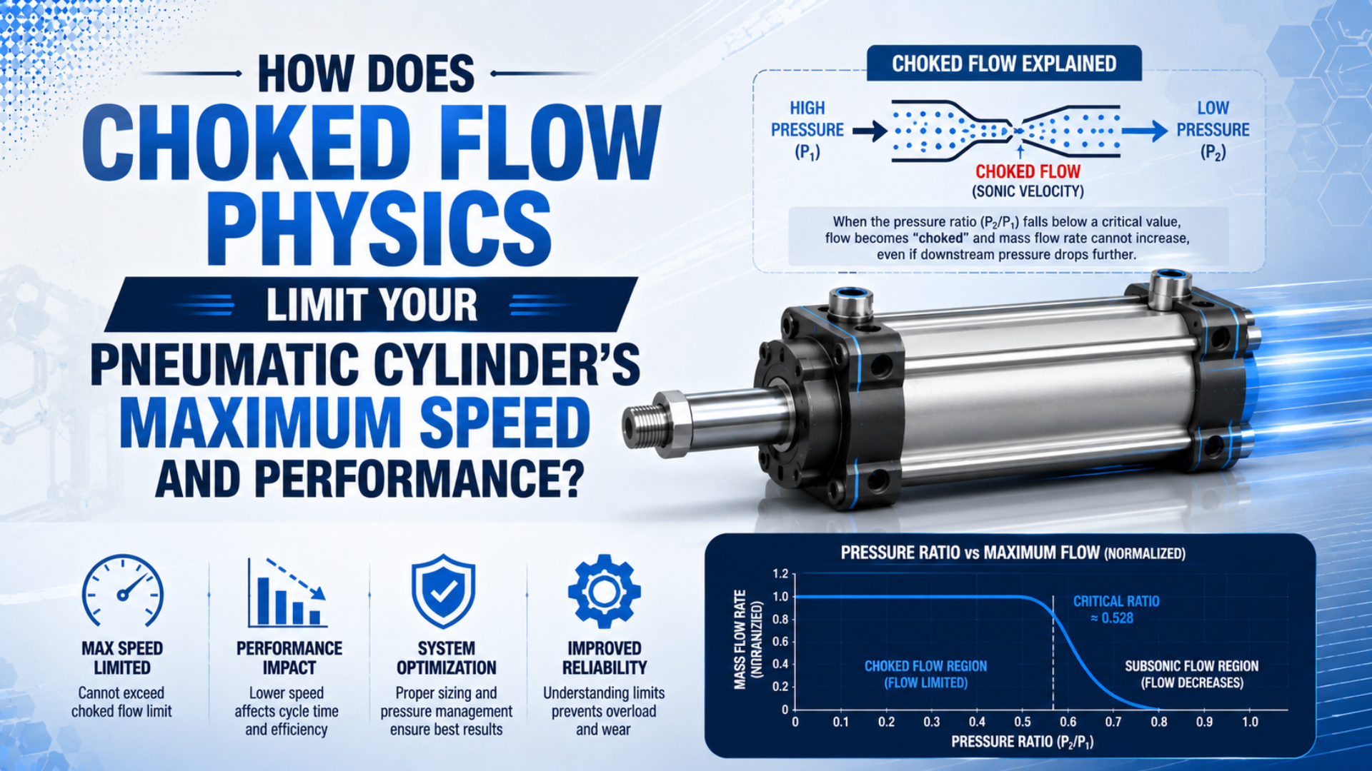
Choked flow physics limits pneumatic cylinder speed when a valve, fitting, tube, speed controller, port, or exhaust device reaches its maximum mass-flow rate. For ideal dry air, the warning boundary is a downstream-to-upstream absolute-pressure ratio near 0.528. Below that ratio, reducing downstream pressure further won’t increase flow through the same restriction (NASA Glenn Research Center, accessed 2026).
That limit belongs to a specific flow path, not to the cylinder as a complete machine. A cylinder can have a choked supply path during extension, a choked exhaust path during retraction, or ordinary pressure loss without sonic choking. Raising upstream pressure can still increase choked mass flow, but it also changes cylinder force, air use, and energy demand. Measure before changing the regulator.
In our experience, the highest-signal first test is a synchronized record of valve-inlet pressure, both cylinder-port pressures, and stroke time. A static regulator gauge cannot show which active path consumes pressure while the piston is moving.
Key Takeaways
- Ideal dry air reaches the sonic boundary near an absolute pressure ratio of 0.528.
- Choking stops additional flow from lower downstream pressure, not from higher upstream pressure.
- Calculate target stroke flow before selecting the valve and tube.
- Test supply and exhaust paths separately with dynamic pressure readings.
What Does Choked Flow Actually Limit?
NASA’s compressible-flow relation reaches maximum mass flow at Mach 1 in the smallest effective area. At that point, a further decrease in downstream pressure cannot send a pressure disturbance upstream through the throat, so the same area cannot pass more mass per second unless upstream total pressure, upstream temperature, or effective area changes (NASA, accessed 2026).
Choked flow is the maximum mass-flow condition at the controlling throat for the specified upstream state. It does not mean that every passage in the circuit is sonic or that the cylinder itself has one permanent maximum speed.
For an ideal gas, the critical downstream-to-upstream pressure ratio is:
Here, is upstream absolute pressure, is downstream absolute pressure, and is the heat-capacity ratio. With for a dry-air estimate, the ratio is approximately 0.528. Gauge pressure cannot be used directly because it omits atmospheric pressure.
Critical pressure ratio is the downstream absolute pressure divided by upstream absolute pressure at the transition to choked behavior. Real pneumatic components can depart from the ideal-gas value, so the datasheet ratio has priority.
The ideal choked mass-flow relation is:
In this equation, is discharge coefficient, is effective throat area, is upstream absolute stagnation pressure, is upstream absolute temperature, and is the gas constant. The practical consequence is easy to miss: choked flow is proportional to upstream absolute pressure. Raising pressure may add flow, but it isn’t a free speed adjustment.
ISO 6358-1 defines steady-state test methods for pneumatic components with fixed or variable internal flow paths. It was confirmed in 2022 and received a measurement-uncertainty amendment in 2026 (ISO 6358-1; ISO 6358-1:2013/Amd 2:2026). When a valve datasheet provides sonic conductance and critical pressure ratio, use those tested values instead of treating 0.528 as a universal component constant.
For a deeper treatment of valve data, see sonic conductance and critical pressure ratio in pneumatic valves.
How Does Flow Become a Cylinder Speed Ceiling?
Parker’s pneumatic valve-sizing example uses a 3.25-inch bore, 12-inch stroke, 80 psig supply, and one-second stroke time to obtain a required Cv of 1.06. The example shows that the motion requirement must be known before valve capacity is selected (Parker Hannifin, accessed 2026).
The kinematic relationship is:
Here, is piston speed, is volumetric flow at the chamber’s actual pressure and temperature, and is piston area for extension or annular area for retraction. Do not divide a catalog SCFM or normal-litre rating directly by piston area. Standard flow must first be converted to the chamber condition.
For a first-pass isothermal estimate of required free-air flow:
In this equation, is stroke, is target stroke time, is estimated absolute chamber pressure, and is the selected normal reference pressure. State the reference condition because NIST notes that standard gas-flow units can assume different temperatures (NIST, updated 2025).
This calculation is a demand estimate, not a guarantee. Dead volume, tube volume, temperature change, seal friction, cushion restriction, pressure buildup, load acceleration, and valve response all affect the measured stroke. Still, it gives the valve and tube review a defensible starting point.
Dynamic cylinder speed is the measured piston travel per unit time while chamber pressures, load, and flow restrictions are changing. It should not be treated as a catalog flow value divided by piston area without pressure conversion.
If available flow is already known, the Cylinder Speed Calculator can estimate extension and retraction speed before real-machine losses are applied.
Why Can Pressure Improve Acceleration but Fail to Fix Speed?
NIST lists one standard atmosphere as 14.6959 psi, so a ratio check using 80 psig and 30 psig must use approximately 94.7 psia and 44.7 psia. The resulting ratio is 0.472, which is below the ideal-air 0.528 boundary (NIST, updated 2025).
That result identifies a choked-flow suspect at the measured restriction. It does not prove the entire actuator has reached a universal speed limit. The valve path may be choked while the exhaust muffler, tube, cushion needle, load, or controller setting remains the stronger limit.
Cylinder motion also changes pressure on both sides of the piston. A useful force balance is:
Here, and are chamber gauge pressures acting in opposite directions, is piston area, is rod-side annular area, and the remaining terms represent friction and external load. Use pascals and square metres for force in newtons, or a consistent customary unit set.
Higher supply pressure can raise the initial pressure differential and shorten acceleration time. Once the moving chamber cannot fill or exhaust fast enough, however, speed stops following the static force calculation. This is why a cylinder can show acceptable force at rest and still miss its cycle time.
Static force and dynamic speed need separate acceptance tests. A pressure reading taken after the piston stops says little about the pressure available halfway through a fast stroke. Record both chamber pressures during motion, then compare them with stroke position or elapsed time.
Which Supply or Exhaust Component Is the Real Restriction?
CAGI states that a well-designed plant-air system commonly keeps pressure drop from compressor discharge to point of use within 10%. It also recommends pressure-monitoring taps because filters, dryers, fittings, piping, valves, and hoses all create losses while air flows (CAGI Pressure Drop Technical Brief, accessed 2026).
Inside a machine, the most restrictive path can change with motion direction. A 5/2 valve uses different spool and exhaust passages for extension and retraction. A one-way speed controller has a free-flow direction and a metered direction. A clogged muffler may affect only one exhaust port. Check the complete active path.
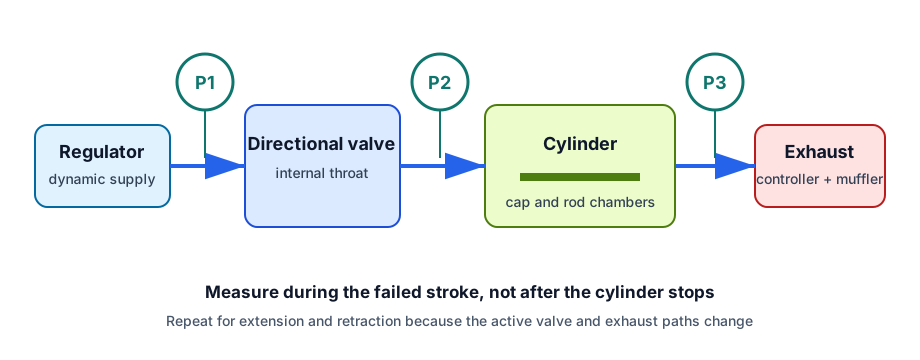
Three dynamic pressure points separate plant-air loss, valve-path restriction, and exhaust back pressure.
| Symptom | Measure first | Likely interpretation |
|---|---|---|
| Both directions slow | P1 at valve inlet | regulator, filter, common supply tube, or shared demand |
| Extension slow only | P1 and cap-end P2 | one valve path, fitting, controller, or cap-end port |
| Retraction slow only | P1 and rod-end P2 | opposite spool path, rod-side connection, or exhaust |
| Speed fades near end | both chamber pressures | cushion restriction, falling pressure differential, or load change |
| Needle fully open but no speed gain | P1, P2, and exhaust P3 | another restriction has become dominant |
| Static force passes but cycle fails | chamber pressures during travel | dynamic fill or exhaust capacity is insufficient |
For broader plant-side troubleshooting, use the compressed-air pressure-drop guide. For the difference between ordinary loss and sonic limiting behavior, see what causes choked flow in pneumatic systems.
How Should You Test a Suspected Speed Limit?
Parker’s worked valve example targets a one-second stroke, while CAGI recommends installing pressure taps rather than relying on one static gauge. Together, those practices define the field test: record dynamic pressure and actual stroke time during the same cycle, at the real load and controller setting (Parker; CAGI).
- Record bore, rod diameter, stroke, load direction, target time, and current time.
- Record valve model, flow rating, active port path, tube ID and length, fittings, speed controllers, and mufflers.
- Install fast-response sensors at the valve inlet and both cylinder ports. Add an exhaust-side point if a muffler or manifold is suspect.
- Log extension and retraction separately. Use the pressure values from the moving part of the stroke.
- Convert gauge pressure to absolute pressure before calculating .
- Compare required cylinder flow with the valve’s manufacturer flow curve or ISO 6358 data.
- Change one restriction at a time, then repeat the pressure trace and timed stroke.
From our work, changing one variable at a time is what makes the trace useful. Simultaneously replacing the valve, tube, fittings, and muffler may improve speed, but it won’t identify the controlling restriction or show which change was necessary.
Suppose the active valve path measures 80 psig upstream and 30 psig downstream during extension. Using NIST’s 14.6959 psi atmospheric value gives 94.7 psia and 44.7 psia. The ratio is 0.472, so that path is below the ideal-air warning boundary. Now check whether the valve’s tested critical ratio agrees and whether the exhaust side also holds excessive back pressure.
A useful diagnosis needs a before-and-after trace, not a louder exhaust sound. If a larger valve raises P2 and shortens the stroke, the valve path mattered. If P2 barely changes, the remaining limit may be tubing, exhaust, cushioning, load, or insufficient point-of-use supply.
The related flow control valve sizing guide explains how stroke demand becomes a capacity selection. The air-flow and pressure guide explains why a flow value cannot predict pressure without the operating path.
A Measurement-First Fix Order
CAGI recommends keeping piping velocity near or below 20 ft/s to reduce turbulence and pressure loss in distribution piping, while its pressure-drop guidance advises increasing tube size and minimizing unnecessary length before raising compressor pressure (CAGI Pressure Drop Technical Brief, accessed 2026). Machine tubing still requires manufacturer-specific sizing at peak flow.
In our experience, the safest sequence starts with demand and measurement, then moves outward from the largest observed pressure loss. This keeps a speed problem from turning into excessive cylinder force, impact energy, or compressed-air consumption.
Use this order:
- Confirm demand. Calculate extension and retraction flow from bore, rod, stroke, pressure, and target time.
- Measure dynamic supply. Fix an undersized or contaminated filter, regulator, common tube, or manifold before changing the actuator.
- Check the active valve path. Compare manufacturer flow curves, Cv sizing data, or ISO 6358 conductance for the exact supply and exhaust paths.
- Remove local bottlenecks. Inspect reducers, elbows, quick couplers, narrow push-in fittings, speed controllers, and cylinder-port adaptors.
- Check exhaust separately. A small muffler or meter-out valve can cap speed even when supply pressure looks healthy.
- Review cushioning and load. End cushioning, stiction, side load, and overhauling loads can imitate a flow ceiling.
- Raise pressure only after review. Recalculate force, component pressure ratings, air consumption, impact energy, and safety margin first.
The smallest thread isn’t automatically the controlling throat. A nominally larger valve can contain a smaller spool window than a compact fitting, while a fully open speed controller can still have a restrictive internal elbow. Compare tested flow data and dynamic pressure, not appearance.
If the results remain ambiguous, send the valve model, bore, rod diameter, stroke, load direction, tube dimensions, controller settings, dynamic pressure trace, and timed stroke through the technical contact page.
The Final Speed-Limit Rule
NASA places maximum ideal mass flow at Mach 1, while ISO 6358-1 defines the steady-state component test framework for pneumatic flow characteristics. Together they support the final rule: calculate cylinder demand, measure the active path during motion, and use tested component data before raising pressure (NASA; ISO).
A cylinder’s practical maximum speed is the point where its available supply and exhaust flow, dynamic pressure differential, load, friction, and cushioning can no longer support faster stable motion. Choked flow may set that ceiling, but only measurements can show whether it occurs in the valve, tube, fitting, controller, port, or exhaust device.
FAQs About Choked Flow and Cylinder Speed
NASA identifies Mach 1 as the maximum-flow condition at a throat, while NIST lists atmospheric pressure as 14.6959 psi for gauge-to-absolute conversion. Those two facts answer most field questions: use absolute pressure, identify the active restriction, and remember that a sonic limit applies to one path rather than the whole actuator (NASA; NIST).
Does choked flow mean increasing supply pressure can never increase cylinder speed?
No. For a fixed throat and temperature, ideal choked mass flow increases with upstream absolute pressure. What stops helping is further reduction of downstream pressure. Raising supply pressure may still increase flow and acceleration, but it also raises force and air demand. Find the restriction and check component ratings before changing pressure.
How can I tell whether the supply or exhaust path is choked?
Measure dynamic pressure on both sides of the suspected restriction during the failed stroke, convert readings to absolute pressure, and calculate . Repeat for the opposite direction. A low ratio identifies a choked-flow suspect; the valve’s ISO 6358 data or manufacturer flow curve should make the final determination.
Can I calculate an exact maximum cylinder speed from Cv alone?
No. Cv can support a manufacturer-approved pneumatic sizing method, but speed also depends on chamber pressure, temperature, valve response, tubing, fittings, exhaust back pressure, load, friction, and cushioning. Calculate target flow first, screen valve capacity, and confirm the result with timed strokes and dynamic pressure traces.
Why does the cylinder have full force at rest but move too slowly?
After motion stops, the chamber has time to approach regulated pressure, so a static force test can pass. During a fast stroke, restricted supply and exhaust paths create different chamber pressures and reduce the usable pressure differential. Record both port pressures during travel to expose that dynamic loss.
Which component should I enlarge first?
Change the component that consumes the largest share of dynamic pressure during the failed motion. It may be a directional valve, tube, fitting, speed controller, manifold passage, cylinder adaptor, or muffler. A larger port thread alone doesn’t prove a larger internal flow path, so compare tested capacity and repeat the same measurement.
Sources and technical references
- NASA Glenn Research Center, Mass Flow Choking, compressible mass-flow equation and Mach 1 maximum-flow condition. Accessed 2026-07-18.
- ISO, ISO 6358-1:2013, steady-state flow-rate testing for pneumatic components using compressible fluids. Confirmed 2022.
- ISO, ISO 6358-1:2013/Amd 2:2026, measurement-uncertainty amendment. Published 2026.
- Parker Hannifin, Pneumatic Valve Products Engineering Data, pneumatic Cv method and worked one-second cylinder example. Accessed 2026-07-18.
- NIST, Pressure and Gas Flow Unit Conversions, pressure conversion and standard gas-flow reference conditions. Updated 2025.
- CAGI, Technical Brief on Pressure Drop, dynamic pressure monitoring and compressed-air pressure-drop guidance. Accessed 2026-07-18.
- AutomationDirect, How to Select a Pneumatic Cylinder, cylinder load, pressure, bore, and stroke selection context. Accessed 2026-07-18.